

Building IoT projects with touchscreens used to be a headache, involving numerous components, messy wiring, and endless troubleshooting. But the ESP32-S3 Box-3 makes things way easier. It is an all-in-one board featuring a dual-core processor, touchscreen, and compatibility with the Arduino IDE. In this tutorial, we’ll take this developer-friendly board ESP32-S3 Box-3 Arduino programming and turn it into a touch-controlled RGB LED controller. There is no need for soldering or, complicated setup.
CircuitDigest presents the Smart Home & Wearables Project Contest 2025! Win exciting prizes worth up to ₹7,00,000 and receive free development boards through our partnership with DigiKey. For registration, dive into contest details.
Let's learn how to program the ESP32-S3 Box-3 using Arduino IDE to create an interactive RGB LED controller with a touchscreen interface. For developers interested in extending similar functionalities, such as sensor data acquisition, display interfacing, and real-time updates, the Desktop Weather Station using ESP32. The project provides detailed implementation examples of IoT data handling and visualisation that can be adapted for advanced game board applications.
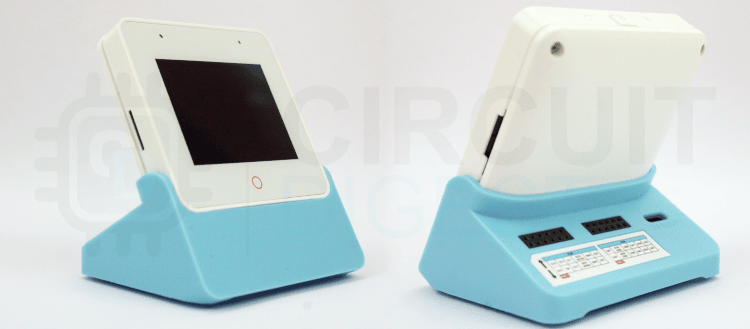
This all-in-one board simplifies hardware setup by including essential components in a single package, allowing both beginners and experienced developers to focus on firmware implementation rather than complex circuit assembly. The built-in 2.4-inch capacitive touchscreen LCD enables the creation of professional user interfaces for embedded applications, perfect for home automation, IoT dashboards, and control systems. Arduino IDE compatibility makes the Box-3 accessible to developers familiar with the Arduino ecosystem. One fascinating project to explore is “Build a Smart Digital Game Board Using Multicolour PCB,” which demonstrates how you can combine multicolour PCB fabrication, addressable LEDs, and an ESP32-S3 to create an interactive digital ludo board
The platform works well for prototyping IoT devices, control systems, AIoT Projects and projects requiring visual and audio feedback. For initial setup and ESP-IDF examples, see our previous unboxing tutorial of ESP32-S3-BOX-3 covering the device basics.
In this step-by-step guide, you'll build a fully functional RGB LED controller with a graphical touchscreen interface using Arduino IDE. This beginner-friendly project will familiarise you with ESP32-S3 programming basics while creating a practical application. The implementation covers the Box-3's key features and provides a foundation for developing more complex interactive applications.
Table of Contents
ESP32-S3 Box-3 Hardware Specs: What Makes It Perfect for IoT Projects
The ESP32-S3 Box-3 incorporates several key components that make it suitable for interactive Arduino programming projects:
- ESP32-S3 dual-core processor running at 240MHz
- 512KB SRAM with an additional 8MB PSRAM
- 16MB flash memory for program storage
- Built-in WiFi and Bluetooth connectivity for wireless IoT applications
- 2.4-inch TFT LCD with 320x240 pixel resolution with ILI9342C controller
- Capacitive touch controller (GT911) supporting multi-touch input
- Adjustable backlight control
- Multiple attachments for expansion, including GPIO headers
- USB-C connector for programming and power
- Built-in speaker and microphone for audio feedback projects
These specifications make the Box-3 particularly well-suited for projects requiring both visual feedback and hardware control, such as our RGB LED controller project.
| Feature | ESP32-S3 Box-3 | Traditional ESP32 | Advantage |
| Display Integration | Built-in 2.4" TFT touchscreen | Requires external display module | Saves $15-25 and reduces wiring |
| Touch Input | Capacitive touch controller (GT911) | Separate touch module needed | Professional multi-touch support |
| Arduino IDE Support | Direct compatibility with version 3.2.1 | Standard ESP32 board support | Optimized libraries included |
| Processor | Dual-core 240MHz + 8MB PSRAM | Dual-core 240MHz (PSRAM optional) | Better multitasking performance |
| Setup Complexity | Plug-and-play with dock | Requires breadboard and wiring | Ready in 5 minutes |
| Audio Capability | Built-in speaker and microphone | External modules required | Voice control ready |
What Is an RGB LED Module and How Does It Work?
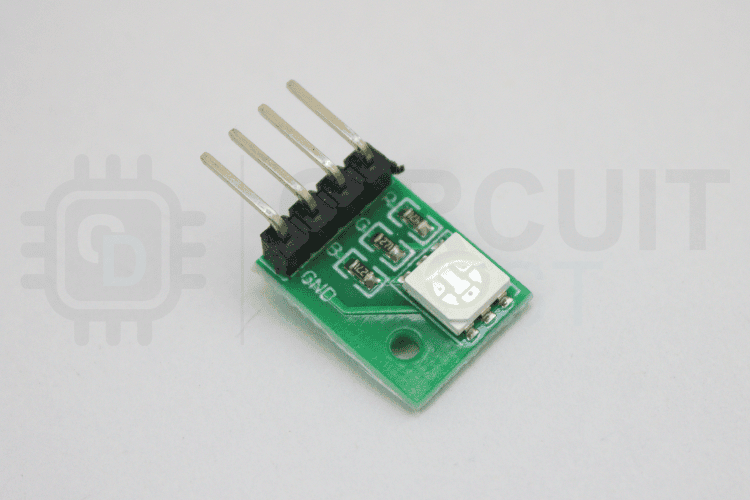
An RGB LED module is a versatile lighting component that can produce millions of colours by mixing red, green, and blue light. The RGB LED module used in this ESP32-S3 Box-3 Arduino programming project contains three separate LEDs (Red, Green, and Blue) within a single package.
Understanding PWM Control for RGB LEDs
The module connects to three GPIO pins configured for PWM (Pulse Width Modulation) output. PWM is a technique that controls LED brightness by rapidly switching the power on and off. Since the LEDs share a common cathode (ground connection), we control brightness by varying the PWM signal at the anodes. A PWM value of 0 turns the LED off, while 255 produces maximum brightness.
This means you can create 256 different brightness levels for each colour, resulting in over 16 million possible colour combinations (256 × 256 × 256). Each LED draws up to 20mA at full brightness. With all three channels active, total current consumption reaches 60mA. The ESP32-S3's GPIO pins can safely source this current, but larger LED arrays would require external driver circuits.
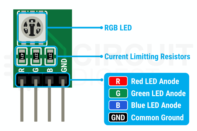
RGB LED Module Pinout and Pin Configuration
As mentioned above, the RGB module contains an RGB LED in a 5050 package, three individual current-limiting resistors, and a four-pin connector for interfacing. The three pins are connected to the anodes of the red, green and blue LEDs through the current limiting resistors, while the fourth one is the common cathode connection. Here is the pinout and parts marking diagram for the RGB module.
| Pin Name | Function | Connection | Voltage |
| R (Red) | Red LED Anode | ESP32-S3 GPIO 39 | 3.3V (PWM) |
| G (Green) | Green LED Anode | ESP32-S3 GPIO 40 | 3.3V (PWM) |
| B (Blue) | Blue LED Anode | ESP32-S3 GPIO 41 | 3.3V (PWM) |
| - (Cathode) | Common Ground | ESP32-S3 GND | 0V (Ground) |
Understanding the ESP32-S3 Box-3 pinout is essential for successful Arduino programming with the ESP32-S3 Box-3.
How to Connect the RGB LED Module to the ESP32-S3 Box-3
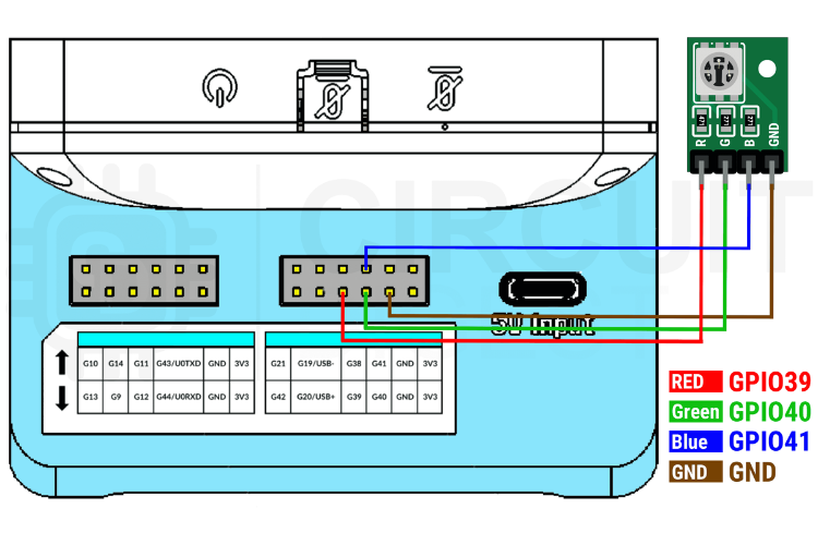
The RGB LED module connects to the ESP32-S3 Box-3 through the expansion header on the dock. The following pin assignments provide optimal performance and avoid conflicts with internal peripherals. Follow this simple wiring guide to connect your RGB LED module:
| RGB LED Pin | ESP32-S3 Box-3 GPIO | Arduino Function | PWM Channel | Max Current |
| Red LED Anode | GPIO 39 | analogWrite(RGB_RED, 0-255) | Channel 0 | 20mA |
| Green LED Anode | GPIO 40 | analogWrite(RGB_GREEN, 0-255) | Channel 1 | 20mA |
| Blue LED Anode | GPIO 41 | analogWrite(RGB_BLUE, 0-255) | Channel 2 | 20mA |
| Common Cathode | GND | Ground Connection | N/A | 60mA total |
The RGB LED module connects to the ESP32-S3 Box-3 through the expansion header using four wire connections. These pins also avoid conflicts with the device's internal peripherals.
Here's the complete pin mapping:
- GPIO pin 39 drives the red LED channel
- GPIO pin 40 controls the green LED channel
- GPIO pin 41 manages the blue LED channel
- The common cathode terminal of the RGB LED connects to the ground (GND) pin on the Box-3
This configuration allows individual PWM control of each colour while sharing a common return path through the ground connection.
Arduino IDE Setup for ESP32-S3 Box-3 Programming
⇒ Step 1: Install Arduino IDE
Before you begin programming, make sure you have the following installed and configured correctly for optimal ESP32-S3 Box-3 Arduino programming:
⇒Step 2: Add ESP32 Board Support (Critical Version)
To start with, the Arduino code first makes sure the ESP32 board is already installed. If you haven't installed the ESP32 board support yet, go to Tools > Board > Board Manager and search for "ESP32". Make sure to install the ESP32 board manager Version 3.2.1, rather than the latest 3.3.0, because at the time of writing this tutorial, the latest version has some compatibility issues with the graphics library we are going to use.
Important: Version 3.3.0 has known issues with the LovyanGFX library, so stick with 3.2.1 for this project.
⇒Step 3: Install Required Libraries
The next step is to install the latest version of the LovyanGFX library through the Arduino IDE library manager. You can find LovyanGFX by searching for "LovyanGFX" in the Library Manager. And for the board, select the ESP32-S3-Box from the tools menu.
⇒ Step 4: Select the Correct Board Configuration
The rest is like programming any other ESP32. Simply connect, code and flash. The firmware creates a simplified RGB LED controller with six predefined colour buttons and an on/off toggle.
Arduino Code Explanation: Programming Your ESP32-S3 RGB Controller
This section breaks down the complete Arduino code with detailed explanations of each component for ESP32-S3 Box-3 Arduino programming beginners.
#include <Arduino.h>
#include <Wire.h>
#define LGFX_ESP32_S3_BOX_V3
#include <LGFX_AUTODETECT.hpp>
#include <LovyanGFX.hpp>
#define RGB_RED   39
#define RGB_GREEN 40
#define RGB_BLUE  41
#define SCREEN_WIDTH  320
#define SCREEN_HEIGHT 240
#define HEADER_HEIGHT 50
#define BUTTON_MARGIN 15
#define BUTTON_ROWS 2
#define BUTTON_COLS 3
#define BUTTON_WIDTH  ((SCREEN_WIDTH - (BUTTON_MARGIN * (BUTTON_COLS + 1))) / BUTTON_COLS)
#define BUTTON_HEIGHT ((SCREEN_HEIGHT - HEADER_HEIGHT - (BUTTON_MARGIN * (BUTTON_ROWS + 1))) / BUTTON_ROWS)
The preprocessor directive LGFX_ESP32_S3_BOX_V3 configures the LovyanGFX library for ESP32-S3 Box-3 hardware. This automatically sets display parameters, SPI communication settings, and touch controller configuration. The Wire library enables I2C communication, though this simplified version relies primarily on LovyanGFX's built-in touch support. GPIO pins 39-41 are selected for RGB LED control because they support PWM output and avoid conflicts with internal peripherals. These pins provide sufficient current capacity for driving standard RGB LEDs without external transistors. The UI layout uses calculated dimensions to ensure buttons fit properly on the 320x240 display. Header height of 50 pixels provides space for the title and toggle switch, while 15-pixel margins create visual separation between interface elements. Button dimensions are calculated automatically based on screen size and margin settings. This approach ensures a consistent layout regardless of display size and makes the interface easily adaptable to different screen resolutions.
struct ColorRGB {
 uint8_t r, g, b;
};
ColorRGB colorButtons[6] = {
 {255, 0, 0},    // RED
 {0, 255, 0},    // GREEN
 {0, 0, 255},    // BLUE
 {255, 255, 150}, // WHITE
 {255, 150, 0},  // YELLOW
 {255, 0, 255}   // PURPLE
};
String colorNames[6] = {"RED", "GREEN", "BLUE", "WHITE", "YELLOW", "PURPLE"};
bool ledOn = true;
int selectedColor = 0; // Default to RED
TouchPoint lastTouch = {0, 0, false};
Three parallel arrays store colour information: RGB values for LED control, colour names for display labels, and system colours for button backgrounds. This organisation simplifies colour management and ensures consistency between display and LED output. State variables track the current LED status, selected colour index, and previous touch position. The selected colour defaults to 0 (RED) to provide immediate visual feedback when the system starts.
void setup() {
 Serial.begin(115200);
 lcd.init();
 lcd.setBrightness(255);
lcd.clear(TFT_BLACK);
 lcd.setFont(&fonts::FreeSans12pt7b);
 lcd.setTextColor(TFT_WHITE);
 lcd.setTextDatum(middle_center);
 lcd.drawString("RGB Controller", SCREEN_WIDTH/2, SCREEN_HEIGHT/2);
pinMode(RGB_RED, OUTPUT);
 pinMode(RGB_GREEN, OUTPUT);
 pinMode(RGB_BLUE, OUTPUT);
 setLEDColor(0, 0, 0);
drawUI();
updateLED();
Serial.println("Setup complete!");
The setup function first initialises the serial communication for debugging, then sets up the display controller and maximum brightness for clear visibility. The startup screen displays a centred title. This test confirms display functionality and provides user feedback during system initialisation. GPIO pins are configured as outputs for PWM control. The setLEDColor(0, 0, 0) call ensures all LEDs start in the OFF state, preventing unexpected illumination during startup. Later, the drawUI function is used to draw the GUI, followed by the updateLED function to update the LED colour.
void loop() {
 TouchPoint touch = readTouch();

 if (touch.touched && !lastTouch.touched) {
   handleTouch(touch.x, touch.y);
 }

 lastTouch = touch;
 delay(50);
}
The main loop implements edge detection for touch events by comparing current and previous touch states using the readTouch function. This prevents continuous triggering when users hold their finger on the screen. The 50ms delay provides a 20Hz update rate. Once a new touch is detected, the loop calls the handle touch functions for the rest.
TouchPoint readTouch() {
 TouchPoint point = {0, 0, false};

 uint16_t x, y;
 if (lcd.getTouch(&x, &y)) {
   point.x = x;
   point.y = y;
   point.touched = true;
 }

 return point;
}
Touch reading relies entirely on LovyanGFX's built-in touch driver, eliminating the need for any additional driver. For that, we are reading these touch input values using the readTouch function. This approach simplifies the implementation while maintaining reliable touch detection.
void drawUI() {
 lcd.clear(COLOR_BG);
 drawHeader();
 drawColorButtons();
}
The UI drawing function clears the screen and redraws all interface elements. This modular approach allows selective updates when only specific elements change, improving performance and reducing flicker.
void drawHeader() {
 lcd.fillRect(0, 0, SCREEN_WIDTH, HEADER_HEIGHT, COLOR_HEADER);

 lcd.setFont(&fonts::Font4);
 lcd.setTextColor(COLOR_WHITE);
 lcd.setTextDatum(middle_left);
 lcd.drawString("RGB LED Control", 15, HEADER_HEIGHT/2);

 drawToggle();
}
The drawHeader function creates a distinct visual area for the title and controls. Font4 provides good readability at the header size, while left-aligned text positioning leaves space for the toggle switch on the right side.
void drawToggle() {
 uint32_t sliderX = ledOn ? TOGGLE_X + TOGGLE_WIDTH - 37 : TOGGLE_X + 3;
 if (ledOn) {
   lcd.fillRoundRect(TOGGLE_X, TOGGLE_Y, TOGGLE_WIDTH, TOGGLE_HEIGHT, TOGGLE_HEIGHT/2, TFT_GREEN);
 } else {
   lcd.fillRoundRect(TOGGLE_X, TOGGLE_Y, TOGGLE_WIDTH, TOGGLE_HEIGHT, TOGGLE_HEIGHT/2, TFT_RED);
 }

 lcd.fillCircle(sliderX + 17, TOGGLE_Y + TOGGLE_HEIGHT/2, 17, COLOR_WHITE);
}
The drawToggle used to draw the slide switch, and uses colour and position to indicate state: green background with right-positioned slider for ON, red background with left-positioned slider for OFF. The slider position calculation ensures smooth visual transitions.
void drawColorButtons() {
 for (int i = 0; i < 6; i++) {
   int row = i / BUTTON_COLS;
   int col = i % BUTTON_COLS;

   int x = BUTTON_MARGIN + col * (BUTTON_WIDTH + BUTTON_MARGIN);
   int y = HEADER_HEIGHT + BUTTON_MARGIN + row * (BUTTON_HEIGHT + BUTTON_MARGIN);

   drawColorButton(i, x, y);
 }
}
The drawColorButtons function is used to draw the predefined colour buttons. It uses a 2x3 grid layout. The row and column calculations distribute buttons evenly across the available space below the header. Once the spacing is calculated, it uses the drawColorButton function to create the button.
void drawColorButton(int colorIndex, int x, int y) {
 if (colorIndex == selectedColor) {
   for (int i = 0; i < 6; i++) {
     lcd.drawRoundRect(x - i, y - i, BUTTON_WIDTH + 2*i, BUTTON_HEIGHT + 2*i, 12, TFT_SILVER);
   }
 } else {
   for (int i = 0; i < 2; i++) {
     lcd.drawRoundRect(x - i, y - i, BUTTON_WIDTH + 2*i, BUTTON_HEIGHT + 2*i, 12, TFT_SILVER);
   }
   for (int i = 2; i < 6; i++) {
     lcd.drawRoundRect(x - i, y - i, BUTTON_WIDTH + 2*i, BUTTON_HEIGHT + 2*i, 12, TFT_BLACK);
   }
 }
}
Button borders use layered drawing to create visual depth. Selected buttons receive a wider border, while unselected buttons get a narrower border. This creates clear visual feedback for the current selection.
void handleTouch(int x, int y) {
 if (x >= TOGGLE_X && x <= TOGGLE_X + TOGGLE_WIDTH &&
     y >= TOGGLE_Y && y <= TOGGLE_Y + TOGGLE_HEIGHT) {
   ledOn = !ledOn;
   drawToggle();
   updateLED();
   return;
 }
for (int i = 0; i < 6; i++) {
   int row = i / BUTTON_COLS;
   int col = i % BUTTON_COLS;

   int buttonX = BUTTON_MARGIN + col * (BUTTON_WIDTH + BUTTON_MARGIN);
   int buttonY = HEADER_HEIGHT + BUTTON_MARGIN + row * (BUTTON_HEIGHT + BUTTON_MARGIN);

   if (x >= buttonX && x <= buttonX + BUTTON_WIDTH &&
       y >= buttonY && y <= buttonY + BUTTON_HEIGHT) {
     selectedColor = i;
     drawColorButtons();
     updateLED();
     return;
   }
 }
Touch handling uses rectangular hit detection for UI elements. The toggle switch occupies its defined area, and touching it toggles the LED state, updates the visual display, and immediately changes the LED output. Colour button detection loops through all six buttons, calculating their positions and checking if the touch coordinates fall within each button's boundaries. When a button is touched, the selection updates, all buttons redraw to show the new selection state, and the LED changes colour.
void updateLED() {
 if (ledOn) {
   ColorRGB color = colorButtons[selectedColor];
   setLEDColor(color.r, color.g, color.b);
 } else {
   setLEDColor(0, 0, 0);
 }
}
void setLEDColor(uint8_t r, uint8_t g, uint8_t b) {
 analogWrite(RGB_RED, r);
 analogWrite(RGB_GREEN, g);
 analogWrite(RGB_BLUE, b);
}
LED control checks the current state and applies the appropriate colour values. When enabled, it uses the selected colour's RGB values. When disabled, it sets all channels to 0. The common cathode configuration allows direct PWM value application without inversion.
Testing Your RGB LED Controller: What to Expect
Once the code is compiled successfully, flash it to the ESP32-S3 Box 3, just like programming any other ESP32-S3 board. Once the firmware is flashed successfully, the box will boot and display the control GUI. Here is a demo of the same.
GitHub Repository with Code and Circuit
Here is the link to our GitHub repository, where you'll find the source code and all other necessary files to build your own RGB LED controller using an ESP32-S3 Box 3 and Arduino IDE.


How to Use the RGB Controller Interface
In the GUI, the header section contains the application title and an on/off toggle switch. Below this, six predefined colour buttons are arranged in a simple 2x3 grid, each labelled with its colour name. Users can touch any of the six colour buttons to change the LED to that colour, with the selected button showing a highlighted border for confirmation. The toggle switch turns the LED on or off while maintaining the current colour selection. The interface responds quickly to touch input and immediately updates both the visual display and the physical LED output.
This ESP32-S3 Box-3 Arduino programming guide was created by embedded systems engineers at Circuit Digest with extensive experience in IoT development and microcontroller programming. Our experts focus on creating practical, hands-on tutorials that help makers and engineers master Raspberry Pi projects, Arduino projects, ESP32 Projects and IoT development projects.
Conclusion: Next Steps in Your ESP32-S3 Journey
Well done for finishing this tutorial on the ESP32-S3 Box-3 with Arduino IDE! You have successfully learnt the basics of ESP32-S3 Box-3 Arduino programming, learning the key aspects of the ESP32-S3 Box-3 pinout, and finally, a touchscreen application from start to finish with hardware interaction.
This project has given you the building blocks of embedded systems and Arduino development. You will have learnt how to control an LED using PWM, how to write applications for touchscreens, how to use and manage GPIOs, and what constitutes UI within an application using it. Many of these fundamental concepts can apply to many other projects, from home automation controllers, IoT dashboards, and simple wireless IoT projects.
Frequently Asked Questions: ESP32-S3 Box-3 Arduino Programming
⇥ 1Q: Can I use different GPIO pins for the RGB LED?
Yes, but ensure you choose PWM-capable pins and avoid pins used by internal peripherals. GPIO 39, 40, and 41 are recommended for optimal performance.
⇥ 2Q: Will this work with common anode RGB LEDs?
You'll need to modify the code to invert the PWM values. Replace analogWrite values with (255-value).
⇥ 3Q: What's the maximum LED current the ESP32-S3 can handle?
Each GPIO can safely source up to 40mA, but it's recommended to stay below 20mA per pin. For higher current LEDs, use a transistor or MOSFET driver.
⇥ 4Q: Can I add more colours to the interface?
Yes! Simply expand the colorButtons array and adjust BUTTON_COLS/BUTTON_ROWS in the code.
⇥ 5Q: What is the procedure for flashing an ESP32-S3 Box-3 with Arduino IDE?
With Arduino IDE, you can use the Board Manager to install board version 3.2.1 for ESP32. After this, go to the Tools > Board menu and pick "ESP32-S3-Box". After that, you can upload your sketch to the device that is connected with USB-C. Take into account that version 3.2.1 is being utilised, so that there will be no conflicts with existing libraries (like LovyanGFX), which will be the case with version 3.3.0 and higher.
⇥ 6Q: What is the recommended version of Arduino IDE to use with the ESP32-S3 Box-3?
Both Arduino IDE 1.8.19 and Arduino IDE 2.x work sufficiently well with the ESP32-S3 Box-3. Be sure to install the board package version 3.2.1. Version 3.3.0 has known compatibility issues with graphics libraries. The LovyanGFX library needs this specific board package version to work well with the touchscreen.
⇥ 7Q: What GPIO pins are on the ESP32-S3 Box-3 available for Arduino projects?
The expansion header offers GPIO 39-41 (PWM-enabled), GPIO 1-2 (UART), GPIO 8-9 (I2C), and GPIO 10-13 (SPI).
I hope you liked this article and learned something new from it. If you have any doubts, you can ask in the comments below or use our forum for a detailed discussion
ESP32-S3 Development Projects and Implementation Examples
Explore a variety of hands-on projects built with the ESP32-S3 module, showcasing its advanced features and processing power. Learn how to implement IoT applications, interactive devices, and smart systems using practical examples.

Wireless Stepper Motor Controller with ESP32 and TMC2240
This tutorial presents an innovative solution for ESP32 stepper motor control, WiFi functionality, allowing you to precisely adjust motor position, track performance, and receive real-time feedback from a simple web browser.

LiteWing ESP32 Drone Firmware - How to Download and Flash?
In this guide, we introduce a custom-built Wireless Stepper Motor Controller with ESP32, a simple yet powerful way to add Wi-Fi stepper motor control to any project. This wireless stepper motor driver integrates robust control with modern connectivity, making it perfect for applications in automation, robotics, and industrial prototyping.

How to Build a Desktop Weather Station Using ESP32 and E-ink Display
This project offers a practical way to build a clean and minimal DIY weather station using an ESP32 microcontroller and an E-Ink display. The use of E-Ink ensures that the display remains readable even without constant power, making it a perfect fit for battery-powered desktop use.
Complete Project Code
#include <Arduino.h>
#include <Wire.h>
#define LGFX_ESP32_S3_BOX_V3
#include <LGFX_AUTODETECT.hpp>
#include <LovyanGFX.hpp>
static LGFX lcd;
// RGB LED pins
#define RGB_RED   39
#define RGB_GREEN 40
#define RGB_BLUE  41
// Display settings
#define SCREEN_WIDTH  320
#define SCREEN_HEIGHT 240
// UI Layout Constants
#define HEADER_HEIGHT 50
#define BUTTON_MARGIN 15
#define BUTTON_ROWS 2
#define BUTTON_COLS 3
// Calculate button dimensions
#define BUTTON_WIDTH  ((SCREEN_WIDTH - (BUTTON_MARGIN * (BUTTON_COLS + 1))) / BUTTON_COLS)
#define BUTTON_HEIGHT ((SCREEN_HEIGHT - HEADER_HEIGHT - (BUTTON_MARGIN * (BUTTON_ROWS + 1))) / BUTTON_ROWS)
// Toggle button settings
#define TOGGLE_WIDTH 70
#define TOGGLE_HEIGHT 40
#define TOGGLE_X (SCREEN_WIDTH - TOGGLE_WIDTH - 15)
#define TOGGLE_Y ((HEADER_HEIGHT - TOGGLE_HEIGHT) / 2)
// Color definitions
#define COLOR_BG      0x1082
#define COLOR_HEADER  0x2124
#define COLOR_WHITE   0xFFFF
#define COLOR_BLACK   0x0000
#define COLOR_GOLD    0xFFE0
// State variables
struct ColorRGB {
 uint8_t r, g, b;
};
struct TouchPoint {
 int16_t x, y;
 bool touched;
};
// 6 predefined colors using LovyanGFX system colors
ColorRGB colorButtons[6] = {
 {255, 0, 0},    // RED
 {0, 255, 0},    // GREEN
 {0, 0, 255},    // BLUE
 {255, 255, 150}, // WHITE
 {255, 150, 0},  // YELLOW
 {255, 0, 255}   // PURPLE
};
String colorNames[6] = {"RED", "GREEN", "BLUE", "WHITE", "YELLOW", "PURPLE"};
uint32_t systemColors[6] = {TFT_RED, TFT_GREEN, TFT_BLUE, TFT_WHITE, TFT_YELLOW, TFT_MAGENTA};
bool ledOn = true;
int selectedColor = 0; // Default to RED
TouchPoint lastTouch = {0, 0, false};
void setup() {
 Serial.begin(115200);
 delay(2000);

 Serial.println("Simple RGB LED Controller Starting...");

 // Initialize display
 Serial.println("Initializing display...");
 lcd.init();
 lcd.setBrightness(255);

 // Test display
 lcd.clear(TFT_BLACK);
 lcd.setFont(&fonts::FreeSans12pt7b);
 lcd.setTextColor(TFT_WHITE);
 lcd.setTextDatum(middle_center);
 lcd.drawString("RGB Controller", SCREEN_WIDTH/2, SCREEN_HEIGHT/2);
 delay(2000);

 // Initialize RGB LED pins
 Serial.println("Initializing RGB LED...");
 pinMode(RGB_RED, OUTPUT);
 pinMode(RGB_GREEN, OUTPUT);
 pinMode(RGB_BLUE, OUTPUT);

 // Turn off LED initially
 setLEDColor(0, 0, 0);

 // Draw UI
 drawUI();
 updateLED();

 Serial.println("Setup complete!");
}
void loop() {
 TouchPoint touch = readTouch();

 if (touch.touched && !lastTouch.touched) {
   handleTouch(touch.x, touch.y);
 }

 lastTouch = touch;
 delay(50);
}
TouchPoint readTouch() {
 TouchPoint point = {0, 0, false};

 uint16_t x, y;
 if (lcd.getTouch(&x, &y)) {
   point.x = x;
   point.y = y;
   point.touched = true;
 }

 return point;
}
void drawUI() {
 // Clear screen
 lcd.clear(COLOR_BG);

 // Draw header
 drawHeader();

 // Draw color buttons
 drawColorButtons();
}
void drawHeader() {
 // Header background
 lcd.fillRect(0, 0, SCREEN_WIDTH, HEADER_HEIGHT, COLOR_HEADER);

 // Title
 lcd.setFont(&fonts::Font4);
 lcd.setTextColor(COLOR_WHITE);
 lcd.setTextDatum(middle_left);
 lcd.drawString("RGB LED Control", 15, HEADER_HEIGHT/2);

 // ON/OFF Toggle
 drawToggle();
}
void drawToggle() {
 uint32_t sliderX = ledOn ? TOGGLE_X + TOGGLE_WIDTH - 37 : TOGGLE_X + 3;
 // Toggle background - GREEN when ON, RED when OFF
 if (ledOn) {
   lcd.fillRoundRect(TOGGLE_X, TOGGLE_Y, TOGGLE_WIDTH, TOGGLE_HEIGHT, TOGGLE_HEIGHT/2, TFT_GREEN);
 } else {
   lcd.fillRoundRect(TOGGLE_X, TOGGLE_Y, TOGGLE_WIDTH, TOGGLE_HEIGHT, TOGGLE_HEIGHT/2, TFT_RED);
 }

 // Toggle slider
 lcd.fillCircle(sliderX + 17, TOGGLE_Y + TOGGLE_HEIGHT/2, 17, COLOR_WHITE);

 // Add shadow effect
 lcd.drawCircle(sliderX + 17, TOGGLE_Y + TOGGLE_HEIGHT/2, 17, COLOR_BLACK);
}
void drawColorButtons() {
 for (int i = 0; i < 6; i++) {
   int row = i / BUTTON_COLS;
   int col = i % BUTTON_COLS;

   int x = BUTTON_MARGIN + col * (BUTTON_WIDTH + BUTTON_MARGIN);
   int y = HEADER_HEIGHT + BUTTON_MARGIN + row * (BUTTON_HEIGHT + BUTTON_MARGIN);

   drawColorButton(i, x, y);
 }
}
void drawColorButton(int colorIndex, int x, int y) {
 // Draw border with layered effect
 if (colorIndex == selectedColor) {
   // Selected - 6px silver border only
   for (int i = 0; i < 6; i++) {
     lcd.drawRoundRect(x - i, y - i, BUTTON_WIDTH + 2*i, BUTTON_HEIGHT + 2*i, 12, TFT_SILVER);
   }
 } else {
   // Non-selected - 2px silver inner + 4px black outer
   // First draw 2px Silver inner border
   for (int i = 0; i < 2; i++) {
     lcd.drawRoundRect(x - i, y - i, BUTTON_WIDTH + 2*i, BUTTON_HEIGHT + 2*i, 12, TFT_SILVER);
   }
   // Then draw 2px Black outer border
   for (int i = 2; i < 6; i++) {
     lcd.drawRoundRect(x - i, y - i, BUTTON_WIDTH + 2*i, BUTTON_HEIGHT + 2*i, 12, TFT_BLACK);
   }
 }

 // Draw button background
 if (colorIndex == 0) {
   // RED
   lcd.fillRoundRect(x, y, BUTTON_WIDTH, BUTTON_HEIGHT, 12, TFT_RED);
 } else if (colorIndex == 1) {
   // GREEN
   lcd.fillRoundRect(x, y, BUTTON_WIDTH, BUTTON_HEIGHT, 12, TFT_GREEN);
 } else if (colorIndex == 2) {
   // BLUE
   lcd.fillRoundRect(x, y, BUTTON_WIDTH, BUTTON_HEIGHT, 12, TFT_BLUE);
 } else if (colorIndex == 3) {
   // WHITE
   lcd.fillRoundRect(x, y, BUTTON_WIDTH, BUTTON_HEIGHT, 12, TFT_WHITE);
 } else if (colorIndex == 4) {
   // YELLOW
   lcd.fillRoundRect(x, y, BUTTON_WIDTH, BUTTON_HEIGHT, 12, TFT_YELLOW);
 } else if (colorIndex == 5) {
   // PURPLE/MAGENTA
   lcd.fillRoundRect(x, y, BUTTON_WIDTH, BUTTON_HEIGHT, 12, TFT_MAGENTA);
 }


 lcd.setFont(&fonts::FreeSansBold9pt7b);if (colorIndex == 3 || colorIndex == 4) {
   // Black text for WHITE and YELLOW
   lcd.setTextColor(TFT_BLACK);
 } else {
   // White text for all other colors
   lcd.setTextColor(TFT_WHITE);
 }
 lcd.setTextDatum(middle_center);
 lcd.drawString(colorNames[colorIndex], x + BUTTON_WIDTH/2, y + BUTTON_HEIGHT/2);

}
void handleTouch(int x, int y) {
 Serial.printf("Touch detected: X=%d, Y=%d\n", x, y);

 // Check if toggle was touched
 if (x >= TOGGLE_X && x <= TOGGLE_X + TOGGLE_WIDTH &&
     y >= TOGGLE_Y && y <= TOGGLE_Y + TOGGLE_HEIGHT) {
   ledOn = !ledOn;
   drawToggle();
   updateLED();
   Serial.println(ledOn ? "LED turned ON" : "LED turned OFF");
   return;
 }

 // Check if any color button was touched
 for (int i = 0; i < 6; i++) {
   int row = i / BUTTON_COLS;
   int col = i % BUTTON_COLS;

   int buttonX = BUTTON_MARGIN + col * (BUTTON_WIDTH + BUTTON_MARGIN);
   int buttonY = HEADER_HEIGHT + BUTTON_MARGIN + row * (BUTTON_HEIGHT + BUTTON_MARGIN);

   if (x >= buttonX && x <= buttonX + BUTTON_WIDTH &&
       y >= buttonY && y <= buttonY + BUTTON_HEIGHT) {

     // Update selection
     selectedColor = i;

     // Redraw ALL color buttons to ensure proper border clearing
     drawColorButtons();

     // Update LED
     updateLED();

     Serial.printf("Color selected: %s (R:%d G:%d B:%d)\n",
                  colorNames[i].c_str(),
                  colorButtons[i].r,
                  colorButtons[i].g,
                  colorButtons[i].b);
     return;
   }
 }
}
void updateLED() {
 if (ledOn) {
   ColorRGB color = colorButtons[selectedColor];
   setLEDColor(color.r, color.g, color.b);
 } else {
   setLEDColor(0, 0, 0);
 }
}
void setLEDColor(uint8_t r, uint8_t g, uint8_t b) {
 // Common cathode RGB LED
 analogWrite(RGB_RED, r);
 analogWrite(RGB_GREEN, g);
 analogWrite(RGB_BLUE, b);
}
