

The Internet of Things (IoT) has revolutionised how we control devices, enabling seamless remote monitoring and operation over a network. This tutorial presents an innovative solution for remote stepper motor control, allowing you to precisely adjust its position, monitor its performance, and receive real-time feedback directly from a simple web browser. For those new to robotics and automation, understanding the basics of a stepper motor and how it works is a great first step before diving into this advanced project. This tutorial presents an innovative solution for ESP32 stepper motor control WiFi functionality, allowing you to precisely adjust motor position, track performance, and receive real-time feedback from a simple web browser.
Wireless Stepper Motor Controller with ESP32 - Quick Overview
Build Time: 8-12 hours | Cost: $50-80 | Difficulty: Intermediate-Advanced
What You'll Learn: WiFi connectivity, SPI/I2C communication, USB-C Power Delivery, Microstepping control
Applications: Robotics automation, CNC machines, Home automation, Industrial prototyping
Table of Contents
In this guide, we introduce a custom-built Wireless Stepper Motor Controller with ESP32, a simple yet powerful way to add Wi-Fi stepper motor control to any project. This wireless stepper motor driver integrates robust control with modern connectivity, making it perfect for applications in automation, robotics, and industrial prototyping. With this wireless stepper driver design, you can control the motor directly through a local web interface, no extra software or complex setup required.
This project was made possible thanks to our sponsors, DigiKey. All the components used in this project were built using parts from DigiKey. You can check out our Project Files with PCB Gerber and BOM to build this wireless stepper motor controller project on your own.
Wireless Stepper Motor Controller - Explained
The Wireless Stepper Motor Controller with ESP32 is a smart motor control system that combines precision stepper motor control with wireless connectivity and intelligent power management.
Wireless Stepper Motor Control: Operate your motor remotely via a simple web interface on any browser or smartphone.
Precision and Accuracy: Achieve high-precision positioning with up to 1/256 microstepping and real-time encoder feedback from the AS5600 sensor.
Smart Power Management: Automatically negotiate optimal power levels from USB-C Power Delivery (PD) sources, from 5V to 20V.
Real-time Monitoring: Monitor critical data, including motor temperature, current draw, and exact position, all updated live on the web dashboard.
Intuitive Visual Feedback: Use colour-coded RGB LED indicators to instantly see the system's power status and motor activity.
Key Features of our Wireless Stepper Driver
- Web-Based Control: Simple HTTP commands control all motor functions - no special software needed
- Precision Movement: up to 1/256 microstepping with closed-loop positioning using AS5600 magnetic encoder
- Smart Power Management: Automatically selects 5V, 9V, 12V, or 15V from USB-PD sources
- Visual Feedback: RGB LEDs show power level (colour-coded) and motor activity (blinking patterns)
- Real-Time Monitoring: Live status updates including temperature, current draw, and position
- Non-Blocking Operation: The Web server stays responsive while the motor runs smoothly
Components Required for the Wireless Stepper Motor Controller Project
Wireless Stepper Motor Controller with ESP32 Wiring Diagram
The complete circuit diagram for the Wireless Stepper Motor Driver is shown below. This comprehensive wireless stepper motor controller with ESP32 wiring diagram demonstrates how to control a stepper motor with ESP32 effectively. It can also be downloaded in PDF format from the GitHub repo linked at the end.

The schematic is fully customizable. You can tweak any part of the design to suit your specific needs.
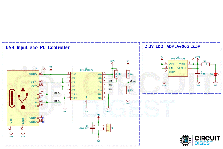
First, the power section, which combines a USB Power Delivery (PD) controller and a Low Dropout (LDO) regulator to manage voltage input and provide a stable 3.3V output. The USB PD controller used is the FUSB302BMPX, which negotiates power profiles through the USB-C connector. It connects to the CC1 and CC2 lines via 5.1kΩ pull-down resistors to detect cable orientation and voltage profiles. Once a power contract is negotiated, the VBUS line delivers the required voltage (e.g., 9V or 12V), which is then passed to the LDO regulator.
The LDO used is the ADP4140002, which steps down the negotiated voltage to a clean 3.3V. This 3.3V is used to power the ESP32-S3 microcontroller, the stepper motor driver’s logic section, the magnetic position sensor, and the indicator LEDs.
The LDO includes input and output capacitors for voltage stability and noise filtering, while the PD controller communicates with the ESP32-S3 via I²C and notifies it of any power events using an interrupt pin.
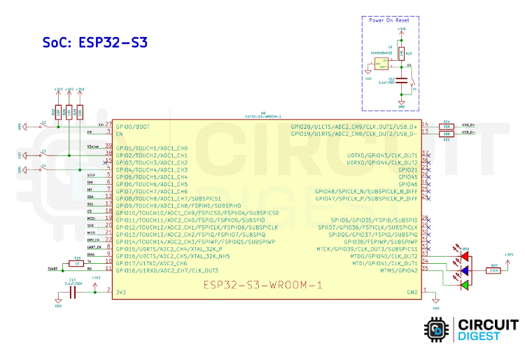
The core of the system is the ESP32-S3-WROOM-1 module, which provides Wi-Fi and Bluetooth connectivity along with multiple GPIOs for control and communication. This setup demonstrates exactly how to control a stepper motor with ESP32 efficiently. Its GPIO0 and EN pins are connected to push buttons for boot mode and reset functionality. It communicates via USB using its native D+ and D– pins, which are routed through 33Ω resistors. Previously, we have built many projects using ESP32 board; you can also check them out if interested.
The I²C bus on GPIO9 (SCL) and GPIO8 (SDA) connects to the USB PD controller and the magnetic position sensor, allowing two-way communication for power and position monitoring. The ESP32 also interfaces with the TMC2240 stepper driver through both SPI and dedicated control pins. It uses GPIO10–13 for SPI communication and GPIO5 and GPIO6 for STEP and DIR signals.
In addition, three LEDs are connected to GPIO40, GPIO41, and GPIO42 via 330Ω resistors, which serve as status indicators.
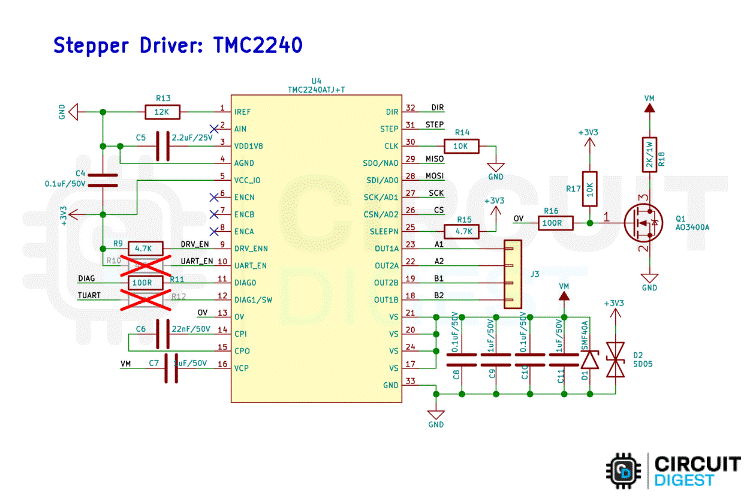
The TMC2240 stepper motor driver handles the precise control of a stepper motor. It receives its motor power input (VM) from an external power source and logic power from the 3.3V LDO. The motor is controlled using STEP and DIR signals from the ESP32, while the SPI bus is used to configure internal settings and read diagnostics. The driver also includes enable and diagnostic pins for fine control and feedback. Protection is implemented using a TVS diode across the VM line to handle voltage spikes and sense resistors for monitoring motor current. The driver’s output pins are connected directly to the motor coils, enabling smooth microstepping operation. For those using A4988 drivers, our A4988 Arduino interface tutorial will guide you step by step.
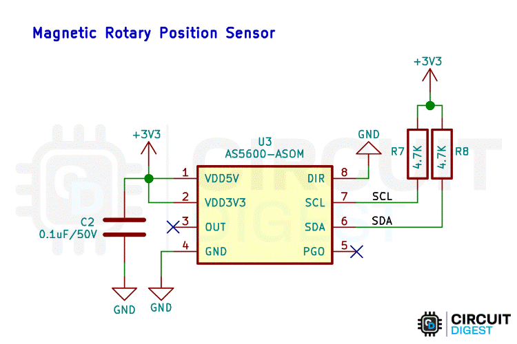
A magnetic rotary position sensor, based on the AS5600, is included for detecting the angular position of a rotating shaft. This sensor communicates over I²C, sharing the same bus as the PD controller. It is powered by the 3.3V rail and includes a decoupling capacitor for noise filtering. The sensor provides precise angle data to the ESP32, enabling closed-loop motor control or position tracking applications.
With this, the Schematic part gets covered. Next comes the PCB Part.
By integrating a versatile ESP32 microcontroller with the high-performance TMC2240 driver and an AS5600 encoder, this ESP32 stepper motor control wifi system provides unmatched precision and real-time feedback.
Custom PCB Design for Wireless Stepper Driver
For this project, we decided to create a custom PCB. This ensures that the final product is as compact as possible and easy to assemble and use. The PCB was designed using KiCad, and all the design files are available for download from the GitHub repository linked below this article.
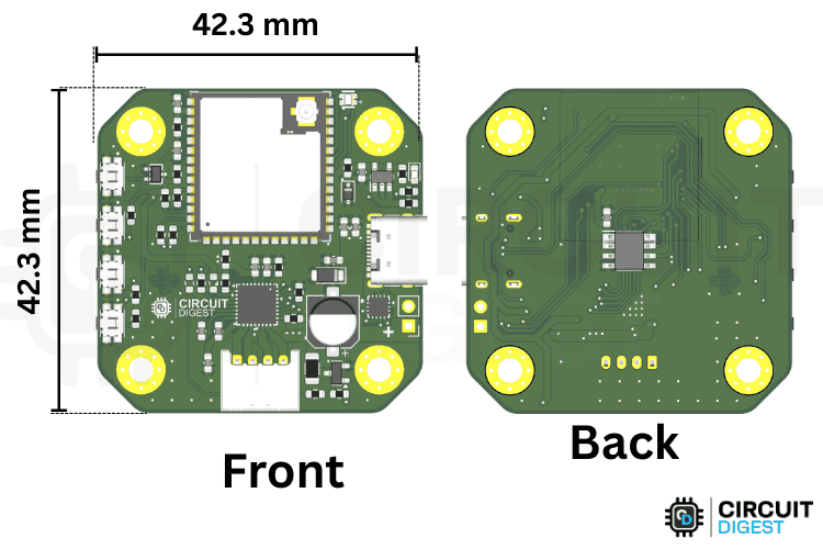
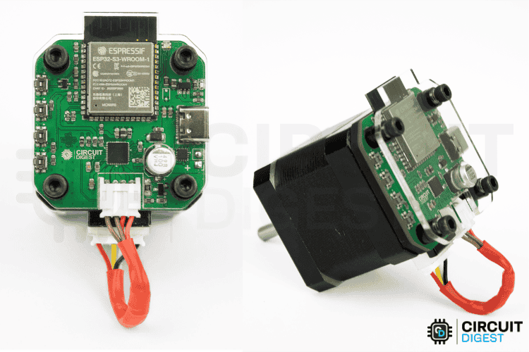
The PCB dimensions are approximately 42.3 mm x 42.3 mm, which is exactly the general size of stepper motors like the NEMA 17. So, it easily mounts behind the motor.
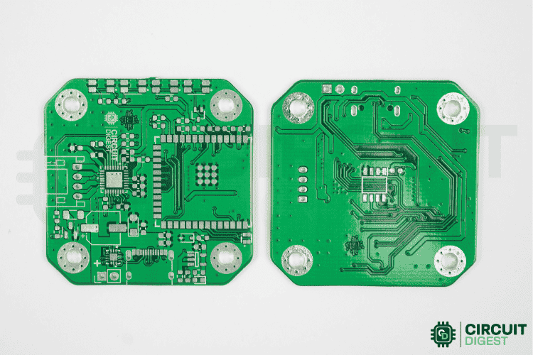
Once the PCB design was complete and fully verified, we sent the respective Gerber files to a PCB fabrication service for manufacturing. Below, you can see the raw fabricated PCB.
Assembling Guide: Building the Stepper Motor Controller
The first step in assembling the PCB was to sort all the required components as listed in the BOM (Bill of Materials). After sorting, we placed the components on the PCB and soldered them one by one.
To simplify this process, you can use an SMD stencil to apply solder paste and then place the components before reflowing the PCB using either an SMD rework station or a reflow oven. However, you are not limited to these methods; manual soldering works just as well for small batches.
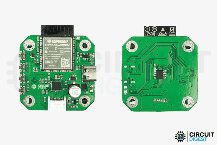
Above is the image of a fully assembled Wireless Stepper Motor Controller PCB.
Laser Cut Enclosure for Stepper Driver
To make the enclosure simple and quick, we chose laser cutting. There are two primary parts we need, along with some washers. At the bottom, we actually need a spacer to compensate for the magnetic encoder IC’s height. On the top, we need to cover the PCB to avoid external damage.
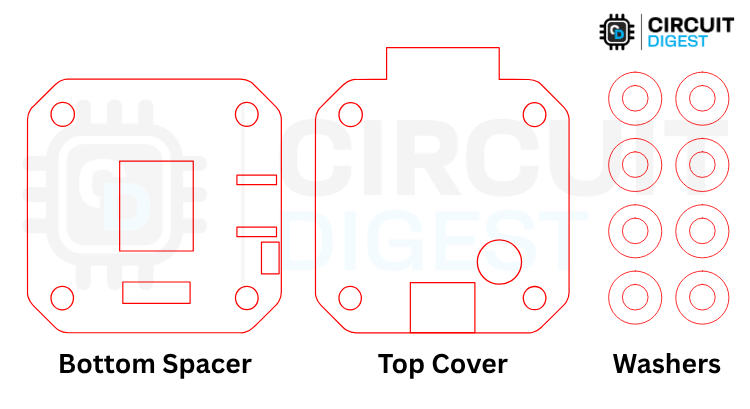
Above, you can see the image of the cutouts.
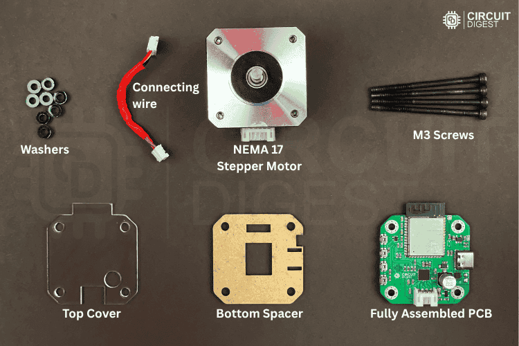
Below, you can see the components required for assembling the Wireless Stepper Motor Driver.
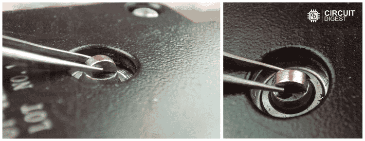
The assembly is very simple. The only part that requires extra attention is the placement of the magnet on the shaft. This is important, as it is responsible for sensing the shaft's position.
I broke a normal 3mm diameter magnet in half and placed one half as shown in the image below. I used Feviquick to stick the magnet.
Next comes the enclosure. It is assembled as shown in the following image.
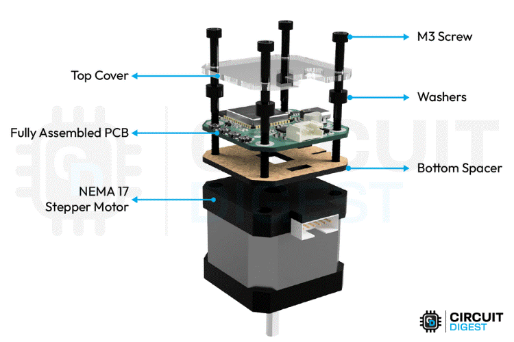
After full assembly, the final project looks like the image below. You can see the compactness of this project.
The reason for not including any side enclosures is to provide ventilation for the driver IC, making it a perfect companion for fast prototyping.
This DIY wireless stepper motor controller project offers a powerful and compact solution for robotics projects and home automation projects. By integrating a versatile ESP32 microcontroller with the high-performance TMC2240 driver and an AS5600 encoder, this system provides unmatched precision and real-time feedback. Its web-based control and smart power management make it an ideal tool for rapid prototyping, robotics, and industrial applications. You can download all the code and design files from the GitHub repository linked below to build your own.
Technical Summary and GitHub Repository
A quick technical summary that outlines the main idea, principle of operations, and main properties of the project. In addition, the GitHub Repository includes the source code, design files, and documentation for ease of use. This summary provides the reader with a quick overview of the project and a sufficient method to replicate it with open-source materials.


Programming the ESP32: Arduino Code Overview
The core of this wireless stepper motor controller project is its versatile Arduino code, which seamlessly integrates several advanced technologies. The firmware demonstrates exactly how to control a stepper motor with ESP32 and is designed to combine:
TMC2240 Stepper Driver: For ultra-quiet and precise stepper motor control.
USB-C Power Delivery: To enable intelligent, variable power sourcing.
AS5600 Magnetic Encoder: For high-resolution, closed-loop position feedback.
RGB Status LEDs: To provide a clear visual indication of system states.
Web Server Interface: For convenient remote control and real-time monitoring.
The system allows you to control a stepper motor through a web browser while monitoring power, temperature, and position in real-time.
Libraries and Dependencies
This code uses several libraries to handle different components.
#include <SPI.h>
#include <WiFi.h>
#include <WebServer.h>
#include "AS5600.h"
#include <Wire.h>
#include <PD_UFP.h>
#include <ArduinoJson.h>
#include "index_page.h"- "SPI.h" – Communicates with the TMC2240 driver using Serial Peripheral Interface (Built-in library)
- "Wire.h" – Handles I2C communication with the magnetic encoder (Built-in library)
- "WiFi.h" and "WebServer.h" – Enable WiFi connectivity and web-based control (Built-in libraries)
- "AS5600.h" – Controls the magnetic encoder for position sensing
- "PD_UFP.h" – Manages USB-C Power Delivery negotiation
- "ArduinoJson.h" – Formats data for web API responses
- "index_page.h" – Contains the HTML/CSS/JavaScript for the web interface (Custom library)
Pin Definitions and Hardware Connections
The system uses specific microcontroller pins for different components to ensure proper communication and control.
const int MOSI_PIN = 11, MISO_PIN = 13, SCK_PIN = 12, CS_PIN = 10;
const int EN_PIN = 14;
const int STEP_PIN = 5;
const int DIR_PIN = 6;
The TMC2240 stepper driver uses an SPI interface with MOSI on pin 11, MISO on pin 13, SCK on pin 12, and CS on pin 10, while motor control pins include Enable on pin 14, Step on pin 5, and Direction on pin 6.
Wire.setPins(8, 9);
The AS5600 magnetic encoder communicates via I2C using pins 8 for SDA and 9 for SCL.
const int RGB_RED_PIN = 40;
const int RGB_GREEN_PIN = 42;
const int RGB_BLUE_PIN = 41;
The RGB LED uses three separate pins for colour control with Red on pin 40, Green on pin 42, and Blue on pin 41.
#define FUSB302_INT_PIN 7The USB-C Power Delivery system uses pin 7 as an interrupt pin for the FUSB302 controller.
Global Variables and Configuration
The system maintains various global variables to track different aspects of operation.
bool isMotorEnabled = false;
bool currentDirection = true;
bool isMovingToAngle = false;
bool pd_negotiation_complete = false;
int currentSpeed = DEFAULT_SPEED;
uint16_t motorCurrent = DEFAULT_CURRENT;
uint8_t microSteps = DEFAULT_MICROSTEPS;
int STEPS_PER_REVOLUTION = STEPS_PER_REV * DEFAULT_MICROSTEPS;
Motor control variables include isMotorEnabled to track whether the motor is powered on, currentDirection to store the rotation direction, and isMovingToAngle to indicate when automatic angle positioning is active. Motor parameters such as currentSpeed, motorCurrent, and microSteps can be adjusted during operation to fine-tune performance.
float targetAngle = 0.0;
float currentAngleTolerance = 0.0;
float cachedCurrentAngle = 0.0;
float cachedTemperature = 0.0;
int cachedCurrentB = 0;
Position control variables like targetAngle and currentAngleTolerance handle precise angle-based movements, while the system caches sensor readings in variables like cachedCurrentAngle and cachedTemperature to reduce communication overhead and improve performance.
struct PDProfile {
   float voltage;
   float current;
   const char* name;
};
const PDProfile pd_profiles[] = {
   {5.0, 3.0, "5V/3A"},
   {9.0, 2.0, "9V/2A"},
   {9.0, 3.0, "9V/3A"},
   {12.0, 1.5, "12V/1.5A"},
   {15.0, 2.0, "15V/2A"},
   {20.0, 1.5, "20V/1.5A"}
};
The power delivery configuration uses a pd_profiles array that defines different voltage and current combinations, including 5V, 9V, 12V, 15V, and 20V options that can be negotiated with USB-C power sources.
const RGBColor COLOR_OFF = { 0, 0, 0 };
const RGBColor COLOR_RED = { 255, 0, 0 };
const RGBColor COLOR_GREEN = { 0, 255, 0 };
const RGBColor COLOR_BLUE = { 0, 0, 255 };
const RGBColor COLOR_YELLOW = { 255, 255, 0 };
const RGBColor COLOR_PURPLE = { 255, 0, 255 };
const RGBColor COLOR_CYAN = { 0, 255, 255 };
const RGBColor COLOR_WHITE = { 255, 255, 255 };
const RGBColor COLOR_ORANGE = { 255, 165, 0 };
const RGBColor COLOR_PINK = { 255, 20, 147 };
LED status management relies on RGB colour constants and timing variables to control the visual feedback system, with different colours indicating various states such as WiFi connectivity, power levels, and motor operation status.
Setup Function - System Initialisation
The setup function initialises all system components in a carefully planned sequence to ensure proper operation for the ESP32 stepper motor control Wi-Fi functionality.
 Serial.begin(115200);
 Serial.println("TMC2240 Stepper Motor Control");

 initRGBLED();
 Wire.setPins(8, 9);
 Wire.begin();
 PD_UFP.init(FUSB302_INT_PIN, PD_POWER_OPTION_MAX_5V);
 PD_UFP.set_power_option(PD_POWER_OPTION_MAX_5V);
 as5600.begin(4);
 as5600.setDirection(AS5600_CLOCK_WISE);
 if (!as5600.isConnected()) {
   Serial.println("Warning: AS5600 encoder not connected!");
 }
 pinMode(EN_PIN, OUTPUT);
 pinMode(STEP_PIN, OUTPUT);
 pinMode(DIR_PIN, OUTPUT);
 pinMode(CS_PIN, OUTPUT);
 pinMode(MOSI_PIN, OUTPUT);
 pinMode(MISO_PIN, INPUT);
 pinMode(SCK_PIN, OUTPUT);
 pinMode(UART_EN_PIN, OUTPUT);
 digitalWrite(CS_PIN, HIGH);
 digitalWrite(EN_PIN, HIGH);                 digitalWrite(UART_EN_PIN, LOW);
 digitalWrite(DIR_PIN, currentDirection);
 SPI.begin(SCK_PIN, MISO_PIN, MOSI_PIN, CS_PIN);
The process begins with serial communication initialisation for debugging purposes, followed by RGB LED testing with a colour sequence of red, green, and blue to verify functionality. Hardware component setup includes configuring I2C communication for the magnetic encoder, initialising the Power Delivery controller with 5V as the starting profile, and setting up all GPIO pins for motor control and SPI communication.
// Connect to WiFi network
 WiFi.begin(ssid, password);
 Serial.print("Connecting to WiFi");
 setRGBColor(COLOR_YELLOW);  // Yellow while connecting
 // Wait for WiFi connection
 while (WiFi.status() != WL_CONNECTED) {
   delay(500);
   Serial.print(".");
 }
 Serial.println("\nConnected to WiFi");
 Serial.print("IP Address: ");
 Serial.println(WiFi.localIP());
 setRGBColor(COLOR_GREEN);  // Green when connected
 delay(1000);
 // Main page route - serves the web interface
 server.on("/", HTTP_GET, []() {
   lastClientRequest = millis();
   webClientConnected = true;
   server.send(200, "text/html", html_page);
 });
 // Motor enable route - enables the stepper motor
 server.on("/enable", HTTP_GET, []() {
   lastClientRequest = millis();
   webClientConnected = true;
   digitalWrite(EN_PIN, LOW);
   isMotorEnabled = true;
   updateMotorStatusColor();
   server.send(200, "text/plain", "Motor Enabled");
 });
 // Motor disable route - disables the stepper motor
 server.on("/disable", HTTP_GET, []() {
   lastClientRequest = millis();
   webClientConnected = true;
   digitalWrite(EN_PIN, HIGH);
   isMotorEnabled = false;
   updateMotorStatusColor();
   server.send(200, "text/plain", "Motor Disabled");
 });
 // Emergency stop route - immediately stops all motor activity
 server.on("/stop", HTTP_GET, []() {
   lastClientRequest = millis();
   webClientConnected = true;
   digitalWrite(EN_PIN, HIGH);
   digitalWrite(STEP_PIN, LOW);
   isMotorEnabled = false;
   isMovingToAngle = false;
   currentSpeed = DEFAULT_SPEED;
   updateMotorStatusColor();
   String response = "{\"status\":\"Emergency Stop Activated\",\"motorEnabled\":false}";
   server.send(200, "application/json", response);
   Serial.println("EMERGENCY STOP ACTIVATED");
 });
 // Speed control route - sets motor speed
 server.on("/speed", HTTP_GET, []() {
   lastClientRequest = millis();
   webClientConnected = true;
   if (server.hasArg("value")) {
     currentSpeed = server.arg("value").toInt();
     server.send(200, "text/plain", "Speed set to " + String(currentSpeed));
   }
 });
 // Manual movement route - moves motor by specified steps
 server.on("/move", HTTP_GET, []() {
   lastClientRequest = millis();
   webClientConnected = true;
   if (server.hasArg("steps")) {
     int targetSteps = server.arg("steps").toInt();
     moveMotor(currentDirection, targetSteps);
     server.send(200, "text/plain", "Moving " + String(targetSteps) + " steps");
   }
 });
 // System status route - returns current system status
 server.on("/status", HTTP_GET, []() {
   lastClientRequest = millis();
   webClientConnected = true;
   bool pd_ready = PD_UFP.is_power_ready();
   float pd_voltage = (pd_ready && pd_negotiation_complete) ? PD_UFP.get_voltage() : 0.0;
   float pd_current = (pd_ready && pd_negotiation_complete) ? PD_UFP.get_current() : 0.0;
   String status = "{\"temperature\":" + String(cachedTemperature, 1) +
                  ",\"current\":" + String(cachedCurrentB) +
                  ",\"pd_ready\":" + String(pd_ready ? "true" : "false") +
                  ",\"pd_negotiated\":" + String(pd_negotiation_complete ? "true" : "false") +
                  ",\"pd_voltage\":" + String(pd_voltage, 2) +
                  ",\"pd_current\":" + String(pd_current, 2) + "}";
   server.send(200, "application/json", status);
 });
 // Motor current control route - sets motor current
 server.on("/current", HTTP_GET, []() {
   lastClientRequest = millis();
   webClientConnected = true;
   if (server.hasArg("value")) {
     motorCurrent = server.arg("value").toInt();
     setCurrent(motorCurrent);
     server.send(200, "text/plain", "Motor current set to " + String(motorCurrent) + " mA");
   }
 });
 // Microstepping control route - sets microstepping resolution
 server.on("/microsteps", HTTP_GET, []() {
   lastClientRequest = millis();
   webClientConnected = true;
   if (server.hasArg("value")) {
     microSteps = server.arg("value").toInt();
     setMicrostepping(microSteps);
     server.send(200, "text/plain", "Microstepping set to 1/" + String(microSteps));
   }
 });
 // Encoder status route - returns current encoder readings
 server.on("/encoder", HTTP_GET, []() {
   lastClientRequest = millis();
   webClientConnected = true;
   String json = String("{\"speed\":0") +
                ",\"rawAngle\":" + String(cachedCurrentAngle, 1) +
                ",\"current\":" + String(cachedCurrentB) + "}";
   server.send(200, "application/json", json);
 });
 // Power status route - returns PD power status
 server.on("/power_status", HTTP_GET, []() {
   lastClientRequest = millis();
   webClientConnected = true;
   StaticJsonDocument<200> doc;
   bool power_ready = PD_UFP.is_power_ready();
   float voltage = 0.0;
   float current = 0.0;
   if (power_ready && pd_negotiation_complete) {
     voltage = PD_UFP.get_voltage();
     current = PD_UFP.get_current();
   }
   bool pd_connected = power_ready && pd_negotiation_complete && voltage > 0.0 && current > 0.0;
   doc["pd_connected"] = pd_connected;
   doc["pd_negotiated"] = pd_negotiation_complete;
   if (pd_connected) {
     doc["voltage"] = voltage;
     doc["current"] = current;
     doc["power"] = voltage * current;
   }
   String response;
   serializeJson(doc, response);
   server.send(200, "application/json", response);
 });
 server.on("/direction", HTTP_GET, []() {
   lastClientRequest = millis();
   webClientConnected = true;
   if (server.hasArg("dir")) {
     currentDirection = (server.arg("dir") == "true");
     digitalWrite(DIR_PIN, currentDirection);
     server.send(200, "text/plain", "Direction set to " + String(currentDirection ? "Forward" : "Backward"));
   } else {
     server.send(400, "text/plain", "Missing direction parameter");
   }
 });
 server.on("/set_angle", HTTP_GET, []() {
   lastClientRequest = millis();
   webClientConnected = true;
   if (server.hasArg("angle")) {
     targetAngle = server.arg("angle").toFloat();
     currentAngleTolerance = calculateAngleTolerance(microSteps);
     isMovingToAngle = true;
     server.send(200, "text/plain", "Moving to angle " + String(targetAngle) + "° with accuracy ±" + String(currentAngleTolerance) + "°");
   } else {
     server.send(400, "text/plain", "Missing angle parameter");
   }
 });
// Web server endpoint to set Power Delivery (PD) profile
server.on("/setPD", HTTP_GET, []() {
 lastClientRequest = millis();
 webClientConnected = true;
 if (server.hasArg("profile")) {
   int profile = server.arg("profile").toInt();
   PD_power_option_t power_option;
   switch (profile) {
     case 5:
       power_option = PD_POWER_OPTION_MAX_5V;
       currentPDProfile = 0;
       break;
     case 9:
       power_option = PD_POWER_OPTION_MAX_9V;
       currentPDProfile = 1;
       break;
     case 12:
       power_option = PD_POWER_OPTION_MAX_12V;
       currentPDProfile = 2;
       break;
     case 15:
       power_option = PD_POWER_OPTION_MAX_15V;
       currentPDProfile = 3;
       break;
     case 20:
       power_option = PD_POWER_OPTION_MAX_20V;
       currentPDProfile = 4;
       break;
     default:
       server.send(400, "text/plain", "Invalid profile");
       return;
   }
   PD_UFP.set_power_option(power_option);

   for (int i = 0; i < 5; i++) {
     PD_UFP.run();
     delay(100);
   }

   forceUpdatePDColors();

   server.send(200, "text/plain", "PD profile set to " + String(profile) + "V");
 } else {
   server.send(400, "text/plain", "Missing profile parameter");
 }
});
// Start the web server
server.begin();
Serial.println("HTTP server started");
// Configure the TMC2240 stepper motor driver
configureDriver();
WiFi connection establishment is a crucial step where the system connects to the specified network, displaying a yellow LED during the connection process and switching to green when successful. The system then displays the assigned IP address for web access. Web server route configuration creates multiple HTTP endpoints, including the root path for serving the main control interface, enable and disable routes for motor power control, parameter adjustment routes for speed, current, and microstepping settings, movement command routes for basic stepping and angle positioning, real-time data routes for status and encoder information, and power delivery management routes. Finally, the TMC2240 driver is configured with default settings, including current limits, microstepping resolution, and chopper timing parameters. To ensure the best performance for your specific motor, you can use our dedicated stepper motor calculator tool
Main Loop - Continuous Operation
The main loop continuously handles multiple tasks to maintain system operation and responsiveness.
 server.handleClient();
 PD_UFP.run();
 updateLEDBlink();
 static unsigned long lastStatusLEDUpdate = 0;
 if (millis() - lastStatusLEDUpdate >= 100) {
   updateStatusLED();
   lastStatusLEDUpdate = millis();
 }
 if (millis() - last_pd_check >= PD_CHECK_INTERVAL) {
   bool was_negotiated = pd_negotiation_complete;

   if (PD_UFP.is_power_ready()) {
     if (!pd_negotiation_complete) {
       Serial.println("PD Power Negotiation Complete!");
       pd_negotiation_complete = true;
       lastPDVoltageCheck = 0;
     }
   } else {
     if (pd_negotiation_complete) {
       Serial.println("PD Power Negotiation Lost!");
       pd_negotiation_complete = false;
       pdColorModeActive = false;        }
   }
   last_pd_check = millis();
 }
Request processing involves the server.handleClient() to handle incoming web requests and PD_UFP.run() to maintain power delivery negotiation with USB-C sources. Visual feedback management updates the LED system based on priority levels, where WiFi connection issues display red blinking, successful PD negotiation shows voltage-coded colours, and normal operation indicates connection status.
 if (millis() - lastEncoderUpdate >= ENCODER_UPDATE_INTERVAL) {
   updateCachedValues();      lastEncoderUpdate = millis();
 }
 if (isMovingToAngle) {
   moveToAngle();    }
 if (millis() - lastStatusUpdate >= STATUS_UPDATE_INTERVAL) {
   Serial.println("System Status: Motor " + String(isMotorEnabled ? "Enabled" : "Disabled") +
                  ", Temp: " + String(cachedTemperature, 1) + "°C" +
                  ", WiFi: " + String(WiFi.status() == WL_CONNECTED ? "Connected" : "Disconnected") +
                  ", Web Client: " + String(webClientConnected ? "Active" : "Inactive") +
                  ", PD Mode: " + String(pdColorModeActive ? "Active" : "Inactive"));
   lastStatusUpdate = millis();
 }
Sensor updates occur periodically to read the magnetic encoder and TMC2240 temperature sensor, with values cached to avoid excessive communication that could slow down the system. Automatic movement functionality activates when isMovingToAngle is true, causing the moveToAngle() function to continuously adjust motor position toward the target angle. Status reporting provides periodic serial output with system information, including motor state, temperature readings, and connection status for debugging and monitoring purposes.
Key Functions Explained
void setRGBColor(RGBColor color) {
 analogWrite(RGB_RED_PIN, color.red);     // Set red component
 analogWrite(RGB_GREEN_PIN, color.green); // Set green component
 analogWrite(RGB_BLUE_PIN, color.blue);   // Set blue component
 currentLEDColor = color;                 // Update current color
}
void updateStatusLED() {
 // Highest Priority: WiFi disconnected - Red fast blink
 if (WiFi.status() != WL_CONNECTED) {
   pdColorModeActive = false;
   enableLEDBlink(COLOR_RED, 200);  // Red fast blink for WiFi issues
   return;
 }
 // Second Priority: PD is ready and negotiated - show voltage colors
 if (PD_UFP.is_power_ready() && pd_negotiation_complete) {
   // Only update PD colors periodically to avoid constant changes
   if (millis() - lastPDVoltageCheck >= PD_CHECK_INTERVAL) {
     updatePDVoltageColor();
     lastPDVoltageCheck = millis();
   }
   return; // Exit here - PD colors are active
 }
 // Third Priority: WiFi connected but no PD - show connection status
 pdColorModeActive = false;
 // Update client connection status based on timeout
 if (millis() - lastClientRequest > CLIENT_TIMEOUT) {
   webClientConnected = false;
 }
 if (webClientConnected) {
   // WiFi connected and web client active - Solid Green
   setRGBColor(COLOR_GREEN);
   ledBlinkEnabled = false;
 } else {
   // WiFi connected but no web client - Blue slow blink
   enableLEDBlink(COLOR_BLUE, 1000);
 }
}
RGB LED control functions such as setRGBColor() and updateStatusLED() manage the visual feedback system that provides immediate status information to users. The system uses a colour-coding scheme where green indicates 5V power, blue represents 9V, purple shows 12V, orange displays 15V, and pink indicates 20V power levels.
// Write data to TMC2240 register via SPI
void writeRegister(uint8_t address, uint32_t value) {
 digitalWrite(CS_PIN, LOW);                    // Select TMC2240
 SPI.transfer(address | 0x80);                 // Send address with write bit
 SPI.transfer((value >> 24) & 0xFF);          // Send MSB
 SPI.transfer((value >> 16) & 0xFF);          // Send byte 2
 SPI.transfer((value >> 8) & 0xFF);           // Send byte 1
 SPI.transfer(value & 0xFF);                  // Send LSB
 digitalWrite(CS_PIN, HIGH);                   // Deselect TMC2240
}
// Read data from TMC2240 register via SPI
uint32_t readRegister(uint8_t address) {
 digitalWrite(CS_PIN, LOW);                    // Select TMC2240
 SPI.transfer(address & 0x7F);                 // Send address with read bit
 uint32_t value = 0;
 value |= (uint32_t)SPI.transfer(0) << 24;    // Read MSB
 value |= (uint32_t)SPI.transfer(0) << 16;    // Read byte 2
 value |= (uint32_t)SPI.transfer(0) << 8;     // Read byte 1
 value |= (uint32_t)SPI.transfer(0);          // Read LSB
 digitalWrite(CS_PIN, HIGH);                   // Deselect TMC2240
 return value;
}
// Set motor current in milliamps
void setCurrent(uint16_t current) {
 uint32_t ihold_irun = 0;
 // Set hold current (current when motor is stationary)
 ihold_irun |= ((current / 100) & 0x1F) << 0;
 // Set run current (current when motor is moving)
 ihold_irun |= ((current / 100) & 0x1F) << 8;
 // Set hold delay (time before reducing to hold current)
 ihold_irun |= ((current / 200) & 0x0F) << 16;
 writeRegister(IHOLD_IRUN, ihold_irun);
}
// Set microstepping resolution (1, 2, 4, 8, 16, 32, 64, 128, 256)
void setMicrostepping(uint8_t microsteps) {
 uint32_t chopconf = readRegister(CHOPCONF);
 chopconf &= ~(0x0F << 24);  // Clear MRES bits
 // Convert microsteps to MRES register value
 uint8_t mres;
 switch (microsteps) {
   case 256: mres = 0x0; break;  // 1/256 microstepping
   case 128: mres = 0x1; break;  // 1/128 microstepping
   case 64:  mres = 0x2; break;  // 1/64 microstepping
   case 32:  mres = 0x3; break;  // 1/32 microstepping
   case 16:  mres = 0x4; break;  // 1/16 microstepping
   case 8:   mres = 0x5; break;  // 1/8 microstepping
   case 4:   mres = 0x6; break;  // 1/4 microstepping
   case 2:   mres = 0x7; break;  // 1/2 microstepping (half step)
   case 1:   mres = 0x8; break;  // Full step
   default:  mres = 0x4; break;  // Default to 1/16 microstepping
 }
 chopconf |= (mres << 24);  // Set MRES bits
 chopconf |= (1 << 28);     // Enable interpolation
 writeRegister(CHOPCONF, chopconf);
 // Update global calculation variables
 STEPS_PER_REVOLUTION = STEPS_PER_REV * microsteps;
 currentAngleTolerance = calculateAngleTolerance(microsteps);
 Serial.print("Microstepping set to 1/");
 Serial.println(microsteps);
}
TMC2240 communication relies on writeRegister() and readRegister() functions that handle SPI communication with the motor driver, while functions like setCurrent() and setMicrostepping() configure motor parameters by writing to specific hardware registers.
// Move motor a specified number of steps in the given direction
void moveMotor(bool direction, uint32_t steps) {
 digitalWrite(DIR_PIN, direction);  // Set direction pin
 static unsigned long lastStepTime = 0;
 static uint32_t stepsRemaining = 0;
 // Initialize step counter on first call
 if (stepsRemaining == 0) {
   stepsRemaining = steps;
   lastStepTime = millis();
 }
 // Generate step pulses at controlled speed
 if (stepsRemaining > 0 && millis() - lastStepTime >= (1000 / currentSpeed)) {
   digitalWrite(STEP_PIN, HIGH);  // Start step pulse
   delayMicroseconds(10);         // Short pulse duration
   digitalWrite(STEP_PIN, LOW);   // End step pulse
   stepsRemaining--;              // Decrement remaining steps
   lastStepTime = millis();       // Update timing
 }
}
// Automatically move motor to target angle with precision control
void moveToAngle() {
 if (!isMovingToAngle) return;  // Exit if not in angle movement mode
 // Calculate angular difference to target
 float angleDifference = targetAngle - cachedCurrentAngle;
 // Normalize angle difference to [-180, 180] range for shortest path
 while (angleDifference > 180) angleDifference -= 360;
 while (angleDifference < -180) angleDifference += 360;
 // Check if target angle is reached within tolerance
 if (abs(angleDifference) <= currentAngleTolerance) {
   isMovingToAngle = false;        // Stop angle movement mode
   digitalWrite(STEP_PIN, LOW);    // Ensure step pin is low
   Serial.println("Target angle reached");
   return;
 }
 // Set motor direction based on angle difference
 currentDirection = (angleDifference > 0);  // Positive = forward
 digitalWrite(DIR_PIN, currentDirection);
 // Enable motor if not already enabled
 if (!isMotorEnabled) {
   digitalWrite(EN_PIN, LOW);  // Enable motor (active low)
   isMotorEnabled = true;
 }
 // Dynamic speed control based on remaining angle
 int stepDelay;
 float absDiff = abs(angleDifference);
 // Slower speeds as we approach target for better precision
 if (absDiff <= 5.0) {
   stepDelay = MIN_STEP_DELAY * 4;      // Very slow for final approach
 } else if (absDiff <= 20.0) {
   stepDelay = MIN_STEP_DELAY * 2;      // Slow for precision zone
 } else if (absDiff <= 45.0) {
   stepDelay = MIN_STEP_DELAY;          // Normal speed
 } else {
   stepDelay = MIN_STEP_DELAY / 2;      // Fast for large movements
 }
 // Take multiple steps toward target (up to 10 per loop iteration)
 for (int i = 0; i < 10 && isMovingToAngle; i++) {
   digitalWrite(STEP_PIN, HIGH);        // Start step pulse
   delayMicroseconds(stepDelay);        // Pulse high time
   digitalWrite(STEP_PIN, LOW);         // End step pulse
   delayMicroseconds(stepDelay);        // Pulse low time
   // Update current angle reading after each step
   cachedCurrentAngle = (as5600.readAngle() * 360.0) / 4096.0;
   angleDifference = targetAngle - cachedCurrentAngle;

   // Re-normalize angle difference
   while (angleDifference > 180) angleDifference -= 360;
   while (angleDifference < -180) angleDifference += 360;
   // Check if target reached during movement
   if (abs(angleDifference) <= currentAngleTolerance) {
     isMovingToAngle = false;
     Serial.println("Target angle reached during movement");
     break;
   }
 }
}
// Calculate angle tolerance based on microstepping resolution
float calculateAngleTolerance(uint8_t microsteps) {
 // Calculate minimum angle step and multiply by 2 for tolerance
 return (360.0 / (200.0 * microsteps)) * 2.0;
}
Motion control functionality includes moveMotor() for generating step pulses for basic movement and moveToAngle() for precise positioning using encoder feedback. The system automatically adjusts movement speed based on the distance remaining to the target angle, using slower speeds for fine positioning and faster speeds for large movements.
Power management through the PD system negotiates appropriate power levels with USB-C sources, allowing the motor to receive optimal voltage ranging from 5V to 20V based on system requirements and source capabilities.
Firmware Upload and Web UI Testing
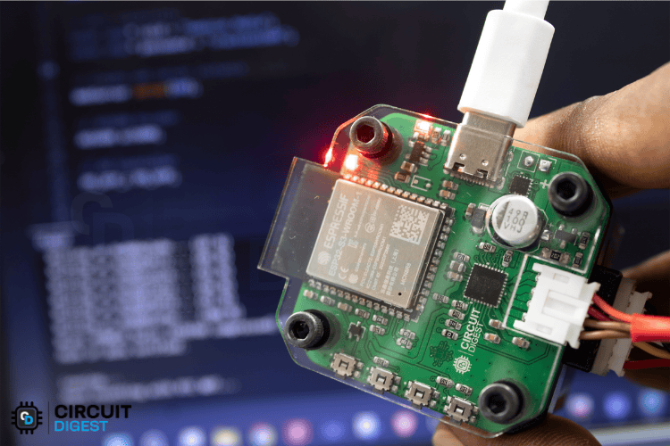
To begin, connect the custom PCB to your computer and upload the code using the Arduino IDE.
If you want to debug via Serial Monitor, don’t forget to enable the CDC (Communication Device Class) setting in the Arduino IDE under Tools > USB Mode before uploading the code.
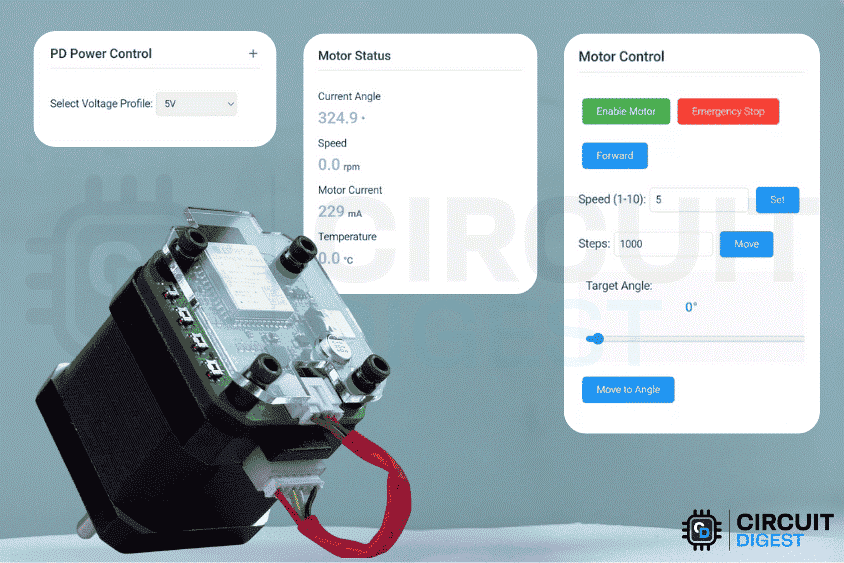
Now let's take a look at the UI. It is simple and self-explanatory.
There are a total of 5 cards,
Motor Configuration (Sets the motor's current (1000 mA) and microstepping mode (1/16 step))
PD Power Control (Selects voltage profile)
System Status (Shows the current system status, commands executed, etc.)
Motor Control (Provides operational controls with enable/disable buttons, emergency stop, directional movement options, speed adjustment, and positioning controls that allow movement by specific step counts or to target angles using either input fields or a slider interface.)
Motor Status (The right panel displays real-time status information, including the current motor angle, rotational speed (RPM), actual motor current draw (mA), and operating temperature.)
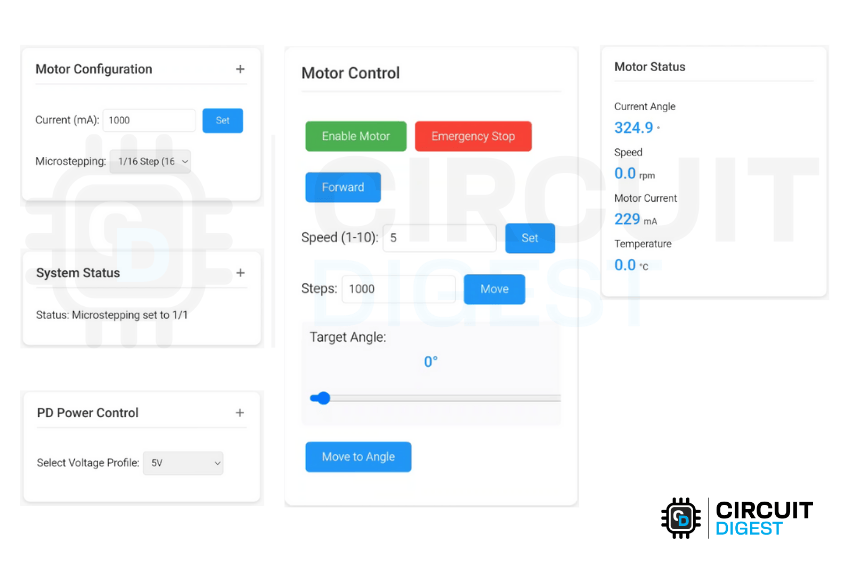
Above, you can see the User Interface of this Wireless Stepper motor controller project. which perfectly demonstrates esp32 stepper motor control wifi capabilities through a modern web interface.
Commonly Asked Questions on Wireless Stepper Motor Controller Project
⇥ Can I use a different stepper motor with this wireless controller?
Yes. Since the TMC2240 driver supports a large number of stepper motors, NEMA 17 and NEMA 23 are a couple of typical examples. You will simply have to adjust the current limit settings on the web interface of the controller from 100mA up to 2000mA to fit your motor specifications. In addition, you can also select microstepping for your motor through the web interface.
⇥ What types of power supply can it accommodate with the given ESP32 stepper controller?
This controller supports USB-C Power Delivery under the 5V to 20V category. It will negotiate for the voltage most suitable to run its wireless stepper motor driver, which will be any one of 5V/3A, 9V/3A, 12V/1.5A, 15V/2A, or 20V/1.5A.
⇥ Can I control multiple stepper motors with one ESP32?
This design was intended for a single ESP32 to control a single motor. To control multiple motors, you must use multiple wireless stepper motor controllers or redesign the circuit to have multiple TMC2240 drivers, each with its own SPI chip select pin.
⇥ What is the controllable range for a wireless stepper motor?
The wireless control range is limited by where the Wi-Fi signal is broadcast from. The range for an indoor setting is usually 30-100 meters, but for applications with longer distances and installations for industrial automation that require extended wireless coverage, it would make sense to use a Wi-Fi repeater or a mesh network.
⇥ How precise is the wireless stepper motor controller project?
The system is very precise with the 1/256 microstepping resolution, and closed loop feedback from the AS5600 encoder, and gives positioning accuracy of ±0.35 degrees for most applications of automation and robotics that require precision motor visibility
Stepper Motor Interfacing Projects
Explore other electronics projects and tutorials, covering circuit design, coding, and control techniques. These projects help you understand motor driver integration, speed control, and precise positioning for robotics and automation applications.

Stepper Motor Interfacing with 8051 Microcontroller
Learn how to control a stepper motor using the 8051 microcontroller (AT89S52) with detailed circuits, drive modes (wave, full-step, half-step), and troubleshooting tips—perfect for robotics, CNC, and automation applications.

Interfacing Stepper Motor with ARM7-LPC2148
Learn how to interface a unipolar stepper motor with the ARM7 LPC2148 microcontroller using the ULN2003 driver

Interfacing Stepper Motor with AVR Microcontroller Atmega16
In this tutorial we will interface 28BYJ-48 Stepper Motor with Atmega16 AVR Microcontroller using Atmel Studio 7.0. We will be interfacing the stepper motor with both the motor drivers i.e. ULN2003 and L293.

Arduino Stepper Motor Tutorial - Interfacing 28-BYJ48 Stepper Motor with Arduino Uno
In this Arduino stepper motor tutorial we will learn about the most commonly available stepper motor 28-BYJ48 and how to interface it with Arduino using ULN2003 stepper motor module.

Interfacing Stepper Motor with STM32F103C8
Learn how to interface a 28BYJ-48 stepper motor with the STM32F103C8 (Blue Pill) using the ULN2003 driver IC. This tutorial covers circuit connections, potentiometer-based speed control, Arduino IDE programming, and stepper motor rotation in both clockwise and anticlockwise directions with practical examples.
Complete Project Code
/*
* ===============================================================================
* TMC2240 STEPPER MOTOR CONTROL WITH PD POWER DELIVERY & RGB STATUS INDICATORS
* ===============================================================================
*
* DESCRIPTION:
* This project implements a comprehensive stepper motor control system using the
* TMC2240 driver with advanced features including PD (Power Delivery) negotiation,
* magnetic encoder feedback, and RGB LED status indication.
*
* MAIN FEATURES:
* 1. TMC2240 Stepper Motor Driver Control
*    - Configurable microstepping (1 to 256 steps)
*    - Current control (up to 2A+)
*    - SPI communication interface
*    - Real-time temperature monitoring
*
* 2. USB-C Power Delivery (PD) Integration
*    - FUSB302 PD controller support
*    - Multiple voltage profiles (5V, 9V, 12V, 15V, 20V)
*    - Automatic power negotiation
*    - Real-time voltage/current monitoring
*
* 3. AS5600 Magnetic Encoder Integration
*    - 12-bit resolution (4096 steps per revolution)
*    - Absolute angle positioning
*    - I2C communication
*    - Precise angle-based motor control
*
* 4. RGB LED Status System
*    - WiFi connection status indication
*    - PD voltage level color coding
*    - Motor state indication (enabled/disabled)
*    - Web client connection status
*
* 5. Web-based Control Interface
*    - Real-time motor control
*    - Parameter adjustment (speed, current, microstepping)
*    - System status monitoring
*    - Emergency stop functionality
*
* 6. Advanced Motion Control
*    - Absolute angle positioning
*    - Dynamic speed control
*    - Precision movement with tolerance
*    - Direction control
*
* WORKING PRINCIPLE:
* The system operates by combining multiple control interfaces:
* - Web interface provides user control and monitoring
* - PD controller manages power delivery from USB-C source
* - TMC2240 drives the stepper motor with precise control
* - AS5600 provides position feedback for closed-loop control
* - RGB LED provides visual status feedback
*
* HARDWARE CONNECTIONS:
* - TMC2240: SPI interface (MOSI=11, MISO=13, SCK=12, CS=10)
* - AS5600: I2C interface (SDA=8, SCL=9)
* - FUSB302: Digital pin 7 for interrupt
* - RGB LED: Pins 40(R), 42(G), 41(B)
* - Motor Control: EN=14, STEP=5, DIR=6, UART_EN=15
*
* AUTHOR: [Rithik Krisna M]
* DATE: [28/05/2025]
* VERSION: 1.0
* ===============================================================================
*/
// ===============================================================================
// LIBRARY INCLUDES
// ===============================================================================
#include <SPI.h>           // SPI communication for TMC2240
#include <WiFi.h>          // WiFi connectivity
#include <WebServer.h>     // HTTP server for web interface
#include "AS5600.h"        // Magnetic encoder library - https://github.com/RobTillaart/AS5600
#include <Wire.h>          // I2C communication
#include <PD_UFP.h>        // USB-C Power Delivery library - https://github.com/kcl93/fusb302_arduino
#include <ArduinoJson.h>   // JSON handling for web API - https://arduinojson.org/?utm_source=meta&utm_medium=library.properties // Version 7.4.1
#include "index_page.h"    // HTML page for web interface
// ===============================================================================
// PIN DEFINITIONS
// ===============================================================================
#define FUSB302_INT_PIN 7  // Interrupt pin for PD controller
// WiFi Configuration
const char* ssid = "xxxx";      // WiFi network name
const char* password = "xxxx";   // WiFi password
// ===============================================================================
// OBJECT INSTANTIATION
// ===============================================================================
WebServer server(80);      // Web server on port 80
AS5600 as5600;            // Magnetic encoder object
PD_UFP_c PD_UFP;          // Power Delivery controller object
// ===============================================================================
// POWER DELIVERY PROFILES CONFIGURATION
// ===============================================================================
// Structure to define PD power profiles with voltage, current, and name
struct PDProfile {
   float voltage;         // Voltage in volts
   float current;         // Current in amperes
   const char* name;      // Human-readable name
};
// Predefined PD power profiles for different voltage levels
const PDProfile pd_profiles[] = {
   {5.0, 3.0, "5V/3A"},      // USB standard power
   {9.0, 2.0, "9V/2A"},      // Quick charge level 1
   {9.0, 3.0, "9V/3A"},      // Quick charge level 2
   {12.0, 1.5, "12V/1.5A"},  // Low power 12V
   {15.0, 2.0, "15V/2A"},    // Medium power 15V
   {20.0, 1.5, "20V/1.5A"}   // High voltage 20V
};
// ===============================================================================
// RGB LED CONFIGURATION
// ===============================================================================
// Pin definitions for RGB LED (common anode or cathode)
const int RGB_RED_PIN = 40;    // Red LED pin
const int RGB_GREEN_PIN = 42;  // Green LED pin
const int RGB_BLUE_PIN = 41;   // Blue LED pin
// RGB color structure for easy color management
struct RGBColor {
 int red;    // Red component (0-255)
 int green;  // Green component (0-255)
 int blue;   // Blue component (0-255)
};
// Predefined color constants for different states
const RGBColor COLOR_OFF = { 0, 0, 0 };         // LED off
const RGBColor COLOR_RED = { 255, 0, 0 };       // Error/disconnected
const RGBColor COLOR_GREEN = { 0, 255, 0 };     // Connected/5V
const RGBColor COLOR_BLUE = { 0, 0, 255 };      // Waiting/9V
const RGBColor COLOR_YELLOW = { 255, 255, 0 };  // Connecting
const RGBColor COLOR_PURPLE = { 255, 0, 255 };  // 12V
const RGBColor COLOR_CYAN = { 0, 255, 255 };    // Special state
const RGBColor COLOR_WHITE = { 255, 255, 255 }; // Unknown/default
const RGBColor COLOR_ORANGE = { 255, 165, 0 };  // 15V
const RGBColor COLOR_PINK = { 255, 20, 147 };   // 20V
// ===============================================================================
// LED STATE MANAGEMENT VARIABLES
// ===============================================================================
unsigned long lastLEDUpdate = 0;       // Last LED update timestamp
unsigned long ledBlinkInterval = 500;   // Blink interval in milliseconds
bool ledBlinkState = false;             // Current blink state (on/off)
RGBColor currentLEDColor = COLOR_OFF;   // Current LED color
bool ledBlinkEnabled = false;           // Blink enable flag
unsigned long lastClientRequest = 0;    // Last web client request time
bool webClientConnected = false;        // Web client connection status
bool pdColorModeActive = false;         // PD color mode active flag
// ===============================================================================
// TMC2240 STEPPER DRIVER CONFIGURATION
// ===============================================================================
// SPI pin definitions for TMC2240 communication
const int MOSI_PIN = 11, MISO_PIN = 13, SCK_PIN = 12, CS_PIN = 10;
// Motor control pin definitions
const int EN_PIN = 14;      // Enable pin (LOW = enabled, HIGH = disabled)
const int STEP_PIN = 5;     // Step pulse pin
const int DIR_PIN = 6;      // Direction pin (HIGH/LOW for CW/CCW)
const int UART_EN_PIN = 15; // UART enable pin (not used in SPI mode)
// ===============================================================================
// TMC2240 REGISTER ADDRESSES
// ===============================================================================
const uint8_t GCONF = 0x00;      // General configuration register
const uint8_t CHOPCONF = 0x6C;   // Chopper configuration register
const uint8_t IHOLD_IRUN = 0x10; // Current control register
const uint8_t TPOWERDOWN = 0x11; // Power down delay register
const uint8_t MSCNT = 0x6A;      // Microstep counter register
const uint8_t MSCURACT = 0x6B;   // Actual microstep current register
const uint8_t SG_RESULT = 0x40;  // StallGuard result register
const uint8_t DRV_STATUS = 0x6F; // Driver status register
const uint8_t ADC_TEMP = 0x51;   // Temperature ADC register
// ===============================================================================
// MOTOR CONFIGURATION CONSTANTS
// ===============================================================================
const uint16_t DEFAULT_CURRENT = 1000;     // Default motor current in mA
const uint8_t DEFAULT_MICROSTEPS = 16;     // Default microstepping setting
const uint16_t DEFAULT_SPEED = 5;          // Default speed in steps/sec
const int STEPS_PER_REV = 200;             // Steps per revolution (1.8° motors)
const int MIN_STEP_DELAY = 100;            // Minimum delay between steps (μs)
// ===============================================================================
// GLOBAL STATE VARIABLES
// ===============================================================================
// Motor state variables
bool isMotorEnabled = false;               // Motor enable state
bool currentDirection = true;              // Current direction (true = forward)
bool isMovingToAngle = false;             // Angle movement in progress flag
bool pd_negotiation_complete = false;     // PD negotiation status
// Motor parameter variables
int currentSpeed = DEFAULT_SPEED;          // Current speed setting
uint16_t motorCurrent = DEFAULT_CURRENT;   // Current motor current setting
uint8_t microSteps = DEFAULT_MICROSTEPS;   // Current microstepping setting
int STEPS_PER_REVOLUTION = STEPS_PER_REV * DEFAULT_MICROSTEPS; // Total steps per rev
// Position control variables
float targetAngle = 0.0;                   // Target angle for movement
float currentAngleTolerance = 0.0;         // Current angle tolerance
float cachedCurrentAngle = 0.0;            // Cached current angle reading
float cachedTemperature = 0.0;             // Cached temperature reading
int cachedCurrentB = 0;                    // Cached current reading
// ===============================================================================
// TIMING CONTROL VARIABLES
// ===============================================================================
unsigned long lastStatusUpdate = 0;        // Last status update timestamp
unsigned long lastEncoderUpdate = 0;       // Last encoder update timestamp
unsigned long last_pd_check = 0;           // Last PD check timestamp
unsigned long lastPDVoltageCheck = 0;      // Last PD voltage check timestamp
// Timing intervals (in milliseconds)
const unsigned long STATUS_UPDATE_INTERVAL = 1000;   // Status update every 1 second
const unsigned long ENCODER_UPDATE_INTERVAL = 100;   // Encoder update every 100ms
const unsigned long PD_CHECK_INTERVAL = 100;         // PD check every 100ms
const unsigned long CLIENT_TIMEOUT = 5000;           // Web client timeout (5 seconds)
// Current PD profile index
int currentPDProfile = 0; // Default to the first profile (5V/3A)
// PD voltage check interval
const unsigned long PD_VOLTAGE_CHECK_INTERVAL = 100;
// ===============================================================================
// RGB LED CONTROL FUNCTIONS
// ===============================================================================
/**
* Set RGB LED to specified color
* @param color RGBColor structure with red, green, blue values
*/
void setRGBColor(RGBColor color) {
 analogWrite(RGB_RED_PIN, color.red);     // Set red component
 analogWrite(RGB_GREEN_PIN, color.green); // Set green component
 analogWrite(RGB_BLUE_PIN, color.blue);   // Set blue component
 currentLEDColor = color;                 // Update current color
}
/**
* Set RGB LED with individual color values
* @param red Red component (0-255)
* @param green Green component (0-255)
* @param blue Blue component (0-255)
*/
void setRGBColor(int red, int green, int blue) {
 RGBColor color = { red, green, blue };
 setRGBColor(color);
}
/**
* Turn off RGB LED and disable blinking
*/
void turnOffLED() {
 setRGBColor(COLOR_OFF);
 ledBlinkEnabled = false;
}
/**
* Enable LED blinking with specified color and interval
* @param color Color to blink
* @param interval Blink interval in milliseconds (default: 500ms)
*/
void enableLEDBlink(RGBColor color, unsigned long interval = 500) {
 currentLEDColor = color;
 ledBlinkInterval = interval;
 ledBlinkEnabled = true;
 ledBlinkState = false;
 lastLEDUpdate = millis();
}
/**
* Update blinking LED state (call in main loop)
* Handles the timing and state changes for LED blinking
*/
void updateLEDBlink() {
 if (!ledBlinkEnabled) return;
 // Check if it's time to toggle the LED
 if (millis() - lastLEDUpdate >= ledBlinkInterval) {
   if (ledBlinkState) {
     setRGBColor(COLOR_OFF);           // Turn off LED
   } else {
     setRGBColor(currentLEDColor);     // Turn on LED with current color
   }
   ledBlinkState = !ledBlinkState;     // Toggle blink state
   lastLEDUpdate = millis();           // Update last update time
 }
}
/**
* Update status LED based on system state priority
* Priority: WiFi > PD Status > Client Connection
*/
void updateStatusLED() {
 // Highest Priority: WiFi disconnected - Red fast blink
 if (WiFi.status() != WL_CONNECTED) {
   pdColorModeActive = false;
   enableLEDBlink(COLOR_RED, 200);  // Red fast blink for WiFi issues
   return;
 }

 // Second Priority: PD is ready and negotiated - show voltage colors
 if (PD_UFP.is_power_ready() && pd_negotiation_complete) {
   // Only update PD colors periodically to avoid constant changes
   if (millis() - lastPDVoltageCheck >= PD_CHECK_INTERVAL) {
     updatePDVoltageColor();
     lastPDVoltageCheck = millis();
   }
   return; // Exit here - PD colors are active
 }

 // Third Priority: WiFi connected but no PD - show connection status
 pdColorModeActive = false;

 // Update client connection status based on timeout
 if (millis() - lastClientRequest > CLIENT_TIMEOUT) {
   webClientConnected = false;
 }
 if (webClientConnected) {
   // WiFi connected and web client active - Solid Green
   setRGBColor(COLOR_GREEN);
   ledBlinkEnabled = false;
 } else {
   // WiFi connected but no web client - Blue slow blink
   enableLEDBlink(COLOR_BLUE, 1000);
 }
}
/**
* Update LED color based on PD voltage level
* Different colors represent different voltage levels:
* Green=5V, Blue=9V, Purple=12V, Orange=15V, Pink=20V, Red=Unknown
*/
void updatePDVoltageColor() {
 float voltage = pd_profiles[currentPDProfile].voltage; // Use selected profile voltage
 RGBColor voltageColor = COLOR_WHITE; // Default for unknown voltage
 // Determine color based on voltage range
 if (voltage >= 4.5 && voltage < 6.0) {
   voltageColor = COLOR_GREEN;          // 5V - Green
 } else if (voltage >= 8.5 && voltage < 10.0) {
   voltageColor = COLOR_BLUE;           // 9V - Blue
 } else if (voltage >= 11.5 && voltage < 13.0) {
   voltageColor = COLOR_PURPLE;         // 12V - Purple
 } else if (voltage >= 14.5 && voltage < 16.0) {
   voltageColor = COLOR_ORANGE;         // 15V - Orange
 } else if (voltage >= 19.0 && voltage < 21.0) {
   voltageColor = COLOR_PINK;           // 20V - Pink
 } else if (voltage > 0.0) {
   voltageColor = COLOR_RED;            // Unknown voltage - Red
 } else {
   voltageColor = COLOR_WHITE;          // No voltage/not ready - White
 }

 // Set PD color mode active
 pdColorModeActive = true;

 // Set blink speed based on motor state
 if (isMotorEnabled) {
   enableLEDBlink(voltageColor, 200);   // Fast blink when motor enabled
 } else {
   enableLEDBlink(voltageColor, 1000);  // Slow blink when motor disabled
 }

 // Debug output for voltage color (can be removed in production)
 if (voltageColor.red == COLOR_GREEN.red && voltageColor.green == COLOR_GREEN.green) Serial.print("GREEN");
 else if (voltageColor.red == COLOR_BLUE.red && voltageColor.green == COLOR_BLUE.green) Serial.print("BLUE");
 else if (voltageColor.red == COLOR_PURPLE.red && voltageColor.green == COLOR_PURPLE.green) Serial.print("PURPLE");
 else if (voltageColor.red == COLOR_ORANGE.red && voltageColor.green == COLOR_ORANGE.green) Serial.print("ORANGE");
 else if (voltageColor.red == COLOR_PINK.red && voltageColor.green == COLOR_PINK.green) Serial.print("PINK");
 else if (voltageColor.red == COLOR_RED.red && voltageColor.green == COLOR_RED.green) Serial.print("RED");
 else Serial.print("WHITE");
}
/**
* Update motor status color when motor state changes
*/
void updateMotorStatusColor() {
 // Only update if PD is ready, otherwise let updateStatusLED handle it
 if (PD_UFP.is_power_ready() && pd_negotiation_complete) {
   updatePDVoltageColor();
 }
}
/**
* Force immediate PD color update (call when motor state changes)
*/
void forceUpdatePDColors() {
 if (PD_UFP.is_power_ready() && pd_negotiation_complete) {
   lastPDVoltageCheck = 0; // Force immediate update
   updatePDVoltageColor();
 }
}
/**
* Initialize RGB LED pins and test sequence
*/
void initRGBLED() {
 // Set pins as outputs
 pinMode(RGB_RED_PIN, OUTPUT);
 pinMode(RGB_GREEN_PIN, OUTPUT);
 pinMode(RGB_BLUE_PIN, OUTPUT);
 // Test sequence to verify LED functionality
 setRGBColor(COLOR_RED);
 delay(200);
 setRGBColor(COLOR_GREEN);
 delay(200);
 setRGBColor(COLOR_BLUE);
 delay(200);
 turnOffLED();
 Serial.println("RGB LED initialized");
}
// ===============================================================================
// TMC2240 DRIVER CONTROL FUNCTIONS
// ===============================================================================
// Function declarations for TMC2240 control
void configureDriver();                              // Configure TMC2240 with default settings
void setCurrent(uint16_t current);                   // Set motor current
void setMicrostepping(uint8_t microsteps);          // Set microstepping resolution
void writeRegister(uint8_t address, uint32_t value); // Write to TMC2240 register
uint32_t readRegister(uint8_t address);             // Read from TMC2240 register
void updateCachedValues();                          // Update cached sensor values
void moveMotor(bool direction, uint32_t steps);     // Move motor specified steps
void moveToAngle();                                 // Move to target angle
float calculateAngleTolerance(uint8_t microsteps);  // Calculate angle tolerance
// ===============================================================================
// MAIN SETUP FUNCTION
// ===============================================================================
void setup() {
 // Initialize serial communication for debugging
 Serial.begin(115200);
 Serial.println("TMC2240 Stepper Motor Control");

 // Initialize RGB LED system
 initRGBLED();

 // Initialize I2C for AS5600 encoder
 Wire.setPins(8, 9);  // Set custom I2C pins
 Wire.begin();
 // Initialize PD controller with 5V maximum initially
 PD_UFP.init(FUSB302_INT_PIN, PD_POWER_OPTION_MAX_5V);
 PD_UFP.set_power_option(PD_POWER_OPTION_MAX_5V);
 // Initialize AS5600 magnetic encoder
 as5600.begin(4);  // Begin with direction pin 4
 as5600.setDirection(AS5600_CLOCK_WISE);
 // Check encoder connection
 if (!as5600.isConnected()) {
   Serial.println("Warning: AS5600 encoder not connected!");
 }
 // Initialize TMC2240 control pins
 pinMode(EN_PIN, OUTPUT);      // Motor enable pin
 pinMode(STEP_PIN, OUTPUT);    // Step pulse pin
 pinMode(DIR_PIN, OUTPUT);     // Direction control pin
 pinMode(CS_PIN, OUTPUT);      // SPI chip select pin
 pinMode(MOSI_PIN, OUTPUT);    // SPI master out, slave in
 pinMode(MISO_PIN, INPUT);     // SPI master in, slave out
 pinMode(SCK_PIN, OUTPUT);     // SPI clock pin
 pinMode(UART_EN_PIN, OUTPUT); // UART enable (not used)
 // Set initial pin states
 digitalWrite(CS_PIN, HIGH);                    // Deselect TMC2240
 digitalWrite(EN_PIN, HIGH);                    // Disable motor initially
 digitalWrite(UART_EN_PIN, LOW);                // Disable UART mode
 digitalWrite(DIR_PIN, currentDirection);       // Set initial direction
 // Initialize SPI communication
 SPI.begin(SCK_PIN, MISO_PIN, MOSI_PIN, CS_PIN);
 // Connect to WiFi network
 WiFi.begin(ssid, password);
 Serial.print("Connecting to WiFi");
 setRGBColor(COLOR_YELLOW);  // Yellow while connecting
 // Wait for WiFi connection
 while (WiFi.status() != WL_CONNECTED) {
   delay(500);
   Serial.print(".");
 }
 Serial.println("\nConnected to WiFi");
 Serial.print("IP Address: ");
 Serial.println(WiFi.localIP());
 setRGBColor(COLOR_GREEN);  // Green when connected
 delay(1000);
 // ===============================================================================
 // WEB SERVER ROUTE CONFIGURATION
 // ===============================================================================

 // Main page route - serves the web interface
 server.on("/", HTTP_GET, []() {
   lastClientRequest = millis();
   webClientConnected = true;
   server.send(200, "text/html", html_page);
 });
 // Motor enable route - enables the stepper motor
 server.on("/enable", HTTP_GET, []() {
   lastClientRequest = millis();
   webClientConnected = true;
   digitalWrite(EN_PIN, LOW);        // Enable motor (active low)
   isMotorEnabled = true;
   updateMotorStatusColor();         // Update LED status
   server.send(200, "text/plain", "Motor Enabled");
 });
 // Motor disable route - disables the stepper motor
 server.on("/disable", HTTP_GET, []() {
   lastClientRequest = millis();
   webClientConnected = true;
   digitalWrite(EN_PIN, HIGH);       // Disable motor (active low)
   isMotorEnabled = false;
   updateMotorStatusColor();         // Update LED status
   server.send(200, "text/plain", "Motor Disabled");
 });
 // Emergency stop route - immediately stops all motor activity
 server.on("/stop", HTTP_GET, []() {
   lastClientRequest = millis();
   webClientConnected = true;
   digitalWrite(EN_PIN, HIGH);       // Disable motor
   digitalWrite(STEP_PIN, LOW);      // Ensure step pin is low
   isMotorEnabled = false;
   isMovingToAngle = false;          // Stop angle movement
   currentSpeed = DEFAULT_SPEED;     // Reset speed
   updateMotorStatusColor();         // Update LED status
   String response = "{\"status\":\"Emergency Stop Activated\",\"motorEnabled\":false}";
   server.send(200, "application/json", response);
   Serial.println("EMERGENCY STOP ACTIVATED");
 });
 // Speed control route - sets motor speed
 server.on("/speed", HTTP_GET, []() {
   lastClientRequest = millis();
   webClientConnected = true;
   if (server.hasArg("value")) {
     currentSpeed = server.arg("value").toInt();
     server.send(200, "text/plain", "Speed set to " + String(currentSpeed));
   }
 });
 // Manual movement route - moves motor by specified steps
 server.on("/move", HTTP_GET, []() {
   lastClientRequest = millis();
   webClientConnected = true;
   if (server.hasArg("steps")) {
     int targetSteps = server.arg("steps").toInt();
     moveMotor(currentDirection, targetSteps);
     server.send(200, "text/plain", "Moving " + String(targetSteps) + " steps");
   }
 });
 // System status route - returns current system status
 server.on("/status", HTTP_GET, []() {
   lastClientRequest = millis();
   webClientConnected = true;
   bool pd_ready = PD_UFP.is_power_ready();
   float pd_voltage = (pd_ready && pd_negotiation_complete) ? PD_UFP.get_voltage() : 0.0;
   float pd_current = (pd_ready && pd_negotiation_complete) ? PD_UFP.get_current() : 0.0;
   String status = "{\"temperature\":" + String(cachedTemperature, 1) +
                  ",\"current\":" + String(cachedCurrentB) +
                  ",\"pd_ready\":" + String(pd_ready ? "true" : "false") +
                  ",\"pd_negotiated\":" + String(pd_negotiation_complete ? "true" : "false") +
                  ",\"pd_voltage\":" + String(pd_voltage, 2) +
                  ",\"pd_current\":" + String(pd_current, 2) + "}";
   server.send(200, "application/json", status);
 });
 // Motor current control route - sets motor current
 server.on("/current", HTTP_GET, []() {
   lastClientRequest = millis();
   webClientConnected = true;
   if (server.hasArg("value")) {
     motorCurrent = server.arg("value").toInt();
     setCurrent(motorCurrent);
     server.send(200, "text/plain", "Motor current set to " + String(motorCurrent) + " mA");
   }
 });
 // Microstepping control route - sets microstepping resolution
 server.on("/microsteps", HTTP_GET, []() {
   lastClientRequest = millis();
   webClientConnected = true;
   if (server.hasArg("value")) {
     microSteps = server.arg("value").toInt();
     setMicrostepping(microSteps);
     server.send(200, "text/plain", "Microstepping set to 1/" + String(microSteps));
   }
 });
 // Encoder status route - returns current encoder readings
 server.on("/encoder", HTTP_GET, []() {
   lastClientRequest = millis();
   webClientConnected = true;
   String json = String("{\"speed\":0") +
                ",\"rawAngle\":" + String(cachedCurrentAngle, 1) +
                ",\"current\":" + String(cachedCurrentB) + "}";
   server.send(200, "application/json", json);
 });
 // Power status route - returns PD power status
 server.on("/power_status", HTTP_GET, []() {
   lastClientRequest = millis();
   webClientConnected = true;
   StaticJsonDocument<200> doc;
   bool power_ready = PD_UFP.is_power_ready();
   float voltage = 0.0;
   float current = 0.0;
   if (power_ready && pd_negotiation_complete) {
     voltage = PD_UFP.get_voltage();
     current = PD_UFP.get_current();
   }
   bool pd_connected = power_ready && pd_negotiation_complete && voltage > 0.0 && current > 0.0;
   doc["pd_connected"] = pd_connected;
   doc["pd_negotiated"] = pd_negotiation_complete;
   if (pd_connected) {
     doc["voltage"] = voltage;
     doc["current"] = current;
     doc["power"] = voltage * current;
   }
   String response;
   serializeJson(doc, response);
   server.send(200, "application/json", response);
 });
 // Direction control route - sets motor direction
 server.on("/direction", HTTP_GET, []() {
   lastClientRequest = millis();
   webClientConnected = true;
   if (server.hasArg("dir")) {
     currentDirection = (server.arg("dir") == "true");
     digitalWrite(DIR_PIN, currentDirection);
     server.send(200, "text/plain", "Direction set to " + String(currentDirection ? "Forward" : "Backward"));
   } else {
     server.send(400, "text/plain", "Missing direction parameter");
   }
 });
 // Angle positioning route - moves motor to specific angle
 server.on("/set_angle", HTTP_GET, []() {
   lastClientRequest = millis();
   webClientConnected = true;
   if (server.hasArg("angle")) {
     targetAngle = server.arg("angle").toFloat();
     currentAngleTolerance = calculateAngleTolerance(microSteps);
     isMovingToAngle = true;
     server.send(200, "text/plain", "Moving to angle " + String(targetAngle) + "° with accuracy ±" + String(currentAngleTolerance) + "°");
   } else {
     server.send(400, "text/plain", "Missing angle parameter");
   }
 });
// Web server endpoint to set Power Delivery (PD) profile
server.on("/setPD", HTTP_GET, []() {
 // Update client activity tracking
 lastClientRequest = millis();
 webClientConnected = true;

 // Check if profile parameter is provided in the request
 if (server.hasArg("profile")) {
   int profile = server.arg("profile").toInt();  // Get requested voltage profile
   PD_power_option_t power_option;  // Variable to store PD power option

   // Map voltage profile to corresponding PD power option and profile index
   switch (profile) {
     case 5:
       power_option = PD_POWER_OPTION_MAX_5V;
       currentPDProfile = 0; // Index of 5V profile in pd_profiles[] array
       break;
     case 9:
       power_option = PD_POWER_OPTION_MAX_9V;
       currentPDProfile = 1; // Index of 9V profile in pd_profiles[] array
       break;
     case 12:
       power_option = PD_POWER_OPTION_MAX_12V;
       currentPDProfile = 2; // Index of 12V profile in pd_profiles[] array
       break;
     case 15:
       power_option = PD_POWER_OPTION_MAX_15V;
       currentPDProfile = 3; // Index of 15V profile in pd_profiles[] array
       break;
     case 20:
       power_option = PD_POWER_OPTION_MAX_20V;
       currentPDProfile = 4; // Index of 20V profile in pd_profiles[] array
       break;
     default:
       // Invalid profile requested - send error response
       server.send(400, "text/plain", "Invalid profile");
       return;
   }
   // Apply the new power option to PD controller
   PD_UFP.set_power_option(power_option);

   // Run PD controller multiple times to ensure negotiation
   for (int i = 0; i < 5; i++) {
     PD_UFP.run();  // Process PD negotiation
     delay(100);    // Small delay between runs
   }

   // Force immediate LED color update to reflect new voltage
   forceUpdatePDColors();

   // Send success response to client
   server.send(200, "text/plain", "PD profile set to " + String(profile) + "V");
 } else {
   // No profile parameter provided - send error response
   server.send(400, "text/plain", "Missing profile parameter");
 }
});
// Start the web server
server.begin();
Serial.println("HTTP server started");
// Configure the TMC2240 stepper motor driver
configureDriver();
}
// Main program loop - runs continuously
void loop() {
 // Handle incoming web server requests
 server.handleClient();

 // Run PD controller to maintain power negotiation
 PD_UFP.run();
 // Update LED blinking animation if enabled
 updateLEDBlink();

 // Update status LED periodically (every 100ms) to avoid constant updates
 static unsigned long lastStatusLEDUpdate = 0;
 if (millis() - lastStatusLEDUpdate >= 100) {
   updateStatusLED();  // Update LED based on system status
   lastStatusLEDUpdate = millis();
 }
 // Handle Power Delivery controller status checks
 if (millis() - last_pd_check >= PD_CHECK_INTERVAL) {
   bool was_negotiated = pd_negotiation_complete;  // Store previous state

   // Check if PD power is ready/negotiated
   if (PD_UFP.is_power_ready()) {
     if (!pd_negotiation_complete) {
       // Power negotiation just completed
       Serial.println("PD Power Negotiation Complete!");
       pd_negotiation_complete = true;
       // Force immediate LED color update to show new voltage
       lastPDVoltageCheck = 0;
     }
   } else {
     if (pd_negotiation_complete) {
       // Power negotiation was lost
       Serial.println("PD Power Negotiation Lost!");
       pd_negotiation_complete = false;
       pdColorModeActive = false;  // Disable PD color mode
     }
   }
   last_pd_check = millis();  // Reset check timer
 }
 // Update cached sensor values periodically
 if (millis() - lastEncoderUpdate >= ENCODER_UPDATE_INTERVAL) {
   updateCachedValues();  // Update angle, temperature, current readings
   lastEncoderUpdate = millis();
 }
 // Handle automatic angle-based motor movement
 if (isMovingToAngle) {
   moveToAngle();  // Continue moving motor to target angle
 }
 // Print system status to serial monitor periodically
 if (millis() - lastStatusUpdate >= STATUS_UPDATE_INTERVAL) {
   Serial.println("System Status: Motor " + String(isMotorEnabled ? "Enabled" : "Disabled") +
                  ", Temp: " + String(cachedTemperature, 1) + "°C" +
                  ", WiFi: " + String(WiFi.status() == WL_CONNECTED ? "Connected" : "Disconnected") +
                  ", Web Client: " + String(webClientConnected ? "Active" : "Inactive") +
                  ", PD Mode: " + String(pdColorModeActive ? "Active" : "Inactive"));
   lastStatusUpdate = millis();
 }
}
// Configure TMC2240 stepper driver with default settings
void configureDriver() {
 // Set motor current and microstepping to default values
 setCurrent(DEFAULT_CURRENT);
 setMicrostepping(DEFAULT_MICROSTEPS);
 // Set power down delay to 0 (immediate power down when idle)
 writeRegister(TPOWERDOWN, 0x0000);
 // Enable step interpolation for smoother movement
 uint32_t gconf = readRegister(GCONF);
 gconf |= (1 << 1);  // Set interpolation bit
 writeRegister(GCONF, gconf);
 // Set chopper off time (TOFF) to 5 for proper operation
 uint32_t chopconf = readRegister(CHOPCONF);
 chopconf &= ~(0x0F << 0);  // Clear TOFF bits
 chopconf |= (5 << 0);      // Set TOFF to 5
 writeRegister(CHOPCONF, chopconf);
 Serial.println("TMC2240 configured with default settings");
}
// Set motor current in milliamps
void setCurrent(uint16_t current) {
 uint32_t ihold_irun = 0;
 // Set hold current (current when motor is stationary)
 ihold_irun |= ((current / 100) & 0x1F) << 0;
 // Set run current (current when motor is moving)
 ihold_irun |= ((current / 100) & 0x1F) << 8;
 // Set hold delay (time before reducing to hold current)
 ihold_irun |= ((current / 200) & 0x0F) << 16;
 writeRegister(IHOLD_IRUN, ihold_irun);
}
// Set microstepping resolution (1, 2, 4, 8, 16, 32, 64, 128, 256)
void setMicrostepping(uint8_t microsteps) {
 uint32_t chopconf = readRegister(CHOPCONF);
 chopconf &= ~(0x0F << 24);  // Clear MRES bits
 // Convert microsteps to MRES register value
 uint8_t mres;
 switch (microsteps) {
   case 256: mres = 0x0; break;  // 1/256 microstepping
   case 128: mres = 0x1; break;  // 1/128 microstepping
   case 64:  mres = 0x2; break;  // 1/64 microstepping
   case 32:  mres = 0x3; break;  // 1/32 microstepping
   case 16:  mres = 0x4; break;  // 1/16 microstepping
   case 8:   mres = 0x5; break;  // 1/8 microstepping
   case 4:   mres = 0x6; break;  // 1/4 microstepping
   case 2:   mres = 0x7; break;  // 1/2 microstepping (half step)
   case 1:   mres = 0x8; break;  // Full step
   default:  mres = 0x4; break;  // Default to 1/16 microstepping
 }
 chopconf |= (mres << 24);  // Set MRES bits
 chopconf |= (1 << 28);     // Enable interpolation
 writeRegister(CHOPCONF, chopconf);
 // Update global calculation variables
 STEPS_PER_REVOLUTION = STEPS_PER_REV * microsteps;
 currentAngleTolerance = calculateAngleTolerance(microsteps);
 Serial.print("Microstepping set to 1/");
 Serial.println(microsteps);
}
// Move motor a specified number of steps in given direction
void moveMotor(bool direction, uint32_t steps) {
 digitalWrite(DIR_PIN, direction);  // Set direction pin
 static unsigned long lastStepTime = 0;
 static uint32_t stepsRemaining = 0;
 // Initialize step counter on first call
 if (stepsRemaining == 0) {
   stepsRemaining = steps;
   lastStepTime = millis();
 }
 // Generate step pulses at controlled speed
 if (stepsRemaining > 0 && millis() - lastStepTime >= (1000 / currentSpeed)) {
   digitalWrite(STEP_PIN, HIGH);  // Start step pulse
   delayMicroseconds(10);         // Short pulse duration
   digitalWrite(STEP_PIN, LOW);   // End step pulse
   stepsRemaining--;              // Decrement remaining steps
   lastStepTime = millis();       // Update timing
 }
}
// Write data to TMC2240 register via SPI
void writeRegister(uint8_t address, uint32_t value) {
 digitalWrite(CS_PIN, LOW);                    // Select TMC2240
 SPI.transfer(address | 0x80);                 // Send address with write bit
 SPI.transfer((value >> 24) & 0xFF);          // Send MSB
 SPI.transfer((value >> 16) & 0xFF);          // Send byte 2
 SPI.transfer((value >> 8) & 0xFF);           // Send byte 1
 SPI.transfer(value & 0xFF);                  // Send LSB
 digitalWrite(CS_PIN, HIGH);                   // Deselect TMC2240
}
// Read data from TMC2240 register via SPI
uint32_t readRegister(uint8_t address) {
 digitalWrite(CS_PIN, LOW);                    // Select TMC2240
 SPI.transfer(address & 0x7F);                 // Send address with read bit
 uint32_t value = 0;
 value |= (uint32_t)SPI.transfer(0) << 24;    // Read MSB
 value |= (uint32_t)SPI.transfer(0) << 16;    // Read byte 2
 value |= (uint32_t)SPI.transfer(0) << 8;     // Read byte 1
 value |= (uint32_t)SPI.transfer(0);          // Read LSB
 digitalWrite(CS_PIN, HIGH);                   // Deselect TMC2240
 return value;
}
// Update cached sensor values (called periodically to reduce I2C/SPI traffic)
void updateCachedValues() {
 // Read and convert encoder angle from raw value to degrees
 cachedCurrentAngle = (as5600.readAngle() * 360.0) / 4096.0;
 // Read TMC2240 temperature sensor with filtering
 uint32_t adc_temp = readRegister(ADC_TEMP);
 int temp_raw = adc_temp & 0x1FFF;           // Extract temperature bits
 float temp_celsius = (temp_raw - 2000) * 0.13; // Convert to Celsius
 // Only update temperature if reading is within reasonable range
 if (temp_celsius >= -50 && temp_celsius <= 150) {
   cachedTemperature = temp_celsius;
 }
 // Read motor current from TMC2240
 uint32_t mscuract = readRegister(MSCURACT);
 cachedCurrentB = mscuract & 0x01FF;  // Extract current bits
}
// Automatically move motor to target angle with precision control
void moveToAngle() {
 if (!isMovingToAngle) return;  // Exit if not in angle movement mode
 // Calculate angular difference to target
 float angleDifference = targetAngle - cachedCurrentAngle;
 // Normalize angle difference to [-180, 180] range for shortest path
 while (angleDifference > 180) angleDifference -= 360;
 while (angleDifference < -180) angleDifference += 360;
 // Check if target angle is reached within tolerance
 if (abs(angleDifference) <= currentAngleTolerance) {
   isMovingToAngle = false;        // Stop angle movement mode
   digitalWrite(STEP_PIN, LOW);    // Ensure step pin is low
   Serial.println("Target angle reached");
   return;
 }
 // Set motor direction based on angle difference
 currentDirection = (angleDifference > 0);  // Positive = forward
 digitalWrite(DIR_PIN, currentDirection);
 // Enable motor if not already enabled
 if (!isMotorEnabled) {
   digitalWrite(EN_PIN, LOW);  // Enable motor (active low)
   isMotorEnabled = true;
 }
 // Dynamic speed control based on remaining angle
 int stepDelay;
 float absDiff = abs(angleDifference);
 // Slower speeds as we approach target for better precision
 if (absDiff <= 5.0) {
   stepDelay = MIN_STEP_DELAY * 4;      // Very slow for final approach
 } else if (absDiff <= 20.0) {
   stepDelay = MIN_STEP_DELAY * 2;      // Slow for precision zone
 } else if (absDiff <= 45.0) {
   stepDelay = MIN_STEP_DELAY;          // Normal speed
 } else {
   stepDelay = MIN_STEP_DELAY / 2;      // Fast for large movements
 }
 // Take multiple steps toward target (up to 10 per loop iteration)
 for (int i = 0; i < 10 && isMovingToAngle; i++) {
   digitalWrite(STEP_PIN, HIGH);        // Start step pulse
   delayMicroseconds(stepDelay);        // Pulse high time
   digitalWrite(STEP_PIN, LOW);         // End step pulse
   delayMicroseconds(stepDelay);        // Pulse low time
   // Update current angle reading after each step
   cachedCurrentAngle = (as5600.readAngle() * 360.0) / 4096.0;
   angleDifference = targetAngle - cachedCurrentAngle;

   // Re-normalize angle difference
   while (angleDifference > 180) angleDifference -= 360;
   while (angleDifference < -180) angleDifference += 360;
   // Check if target reached during movement
   if (abs(angleDifference) <= currentAngleTolerance) {
     isMovingToAngle = false;
     Serial.println("Target angle reached during movement");
     break;
   }
 }
}
// Calculate angle tolerance based on microstepping resolution
float calculateAngleTolerance(uint8_t microsteps) {
 // Calculate minimum angle step and multiply by 2 for tolerance
 return (360.0 / (200.0 * microsteps)) * 2.0;
}
