
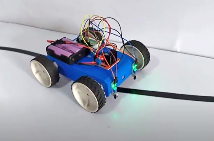
This Robot can follow any line and can reach its destination automatically, by tracking any line. This can be used to move to places in factories and industries to move anything without any control of a user or computer. This moves based on the sensor data that the IR Sensor gives as output. The sensor works on the principle of reflection and refraction of light. Infrared light bends more as compared to visible light (i.e. VIBGYOR). And we know that black colour absorbs most of the light which is falling on it (Basically black colour is anything that we cannot see, there is no colour, called black). Similarly here also when the IR Led is perpendicular to the line, it absorbs and does not reflect the light black. Whereas when the IR Led is perpendicular to any other colour, it reflects back the Infrared light. When the left sensor reflects the Infrared light, and the right does not, it means that the robot must move towards the right and vice versa. Again when both sensors reflect the Infrared light, the robot must move straight and when both sensors do not reflect any Infrared light, the robot stops moving. By this principle the robot works. In this project, we will build this robot using raspberry pi pico. So, we will use Thonny IDE to program our Rasperry Pi. For a better understanding, you can check out our perviously built raspberry pi pico based projects.
Previously, we built some line follower projects using different microcontrollers,
- Line Follower Robot using Arduino
- Line Follower Robot using 8051 Microcontroller
- Line Follower Robot Using MSP430 LaunchPad
- Line Follower Robot using AVR Microcontroller ATmega16
- Line Follower Robot using PIC Microcontroller
- How to Make Line Following Robot without using Microcontroller
Component Required for Line Following Robot
Project Used Hardware
- Raspberry Pi Pico
- L298N Motor Driver
- 2x IR Sensor
- 12V Battery
- 4x Motors
- 4x Wheels
Project Used Software
- Thonny IDE
Hardware and Software Selection
For this project, I have selected the Raspberry Pi Pico because it is a newly launched board with much more advanced features. Before the launch of this new microcontroller board, I was experimenting with various arduinos for building a line following robot. Then finally I realized it will be better to use a small arduino board or ony microcontroller IC such as Atmega328P for this project, since it will reduce the size and weight of the robot. This will also consume less current compared to others. But after the launch of this new advanced board, in the past January, 2021 I planned to make the robot with Raspberry Pi Pico. The first and the foremost reason behind this is that this board will consume very low current, besides the most amazing fact is that this board has a on-board buck-boost converter that enables us to use this board in just a very limited amount of voltage, as low as 1.5 V.
Now for the software in case, we can use either Thonny IDE or Arduino IDE. But I have chosen Thonny IDE because this IDE enables us to use MicroPython and Circuit Python for programming. Since Python requires very less coding compared to Arduino and C++, I have chosen this platform for programming. I have chosen the Raspberry Pi Pico because it is way better as it has a clock frequency of 133 MHz compared to the Arduino Nano which has a clock frequency of 16 MHz. Also, it has many more features like the built-in Temperature Sensor(although it has no use in this project). So in comparison with Arduino Nano, the Raspberry Pi Pico is a way better option to choose. The IR Sensor can be replaced with other kinds of Lidar Sensors.
Line Following Robot Circuit Diagram

Here the two IR Sensors are connected to the Gpio pin 2 and 3 of the Pi Pico. The Motor Driver pins are connected to the Gpio Pins 10,11,12 and 13 of the Pi Pico. The enable pins are connected to the Gpio pins 6 and 7 of the Pi Pico. These Pins exchange PWM signals between the Pi Pico and the Motor Driver.
Complete Project Code
# Raspberry Pi Pico based Line Following Robot
from machine import Pin,PWM #importing PIN and PWM
import time #importing time
import utime
# Defining motor pins
motor1=Pin(10,Pin.OUT)
motor2=Pin(11,Pin.OUT)
motor3=Pin(12,Pin.OUT)
motor4=Pin(13,Pin.OUT)
# Defining enable pins and PWM object
enable1=PWM(Pin(6))
enable2=PWM(Pin(7))
# Defining  right and left IR digital pins as input
right_ir = Pin(2, Pin.IN)
left_ir = Pin(3, Pin.IN)
# Defining frequency for enable pins
enable1.freq(1000)
enable2.freq(1000)
# Setting maximum duty cycle for maximum speed
enable1.duty_u16(65025)
enable2.duty_u16(65025)
# Forward
def move_forward():
    motor1.low()
    motor2.high()
    motor3.high()
    motor4.low()
# Backward
def move_backward():
    motor1.high()
    motor2.low()
    motor3.low()
    motor4.high()
#Turn Right
def turn_right():
    motor1.low()
    motor2.high()
    motor3.low()
    motor4.high()
#Turn Left
def turn_left():
    motor1.high()
    motor2.low()
    motor3.high()
    motor4.low()
#Stop
def stop():
    motor1.low()
    motor2.low()
    motor3.low()
    motor4.low()
while True:
    right_val=right_ir.value() #Getting right IR value(0 or 1)
    left_val=left_ir.value() #Getting left IR value(0 or 1)
    print(str(right_val)+"-"+str(left_val))
    # Controlling robot direction based on IR value
    if right_val==0 and left_val==0:
        move_forward()
    elif right_val==1 and left_val==0:
        turn_right()
    elif right_val==0 and left_val==1:
        turn_left()
    else:
        stop()
