
Line follower Robot (LFR) is a machine that follows a line, it may be a black line or a white line. The line following bot is beginner-friendly and interesting to understand and build. While Line follower bots are popular and common to be built with Arduino or other microcontrollers, let’s try to build the same without a microcontroller and actually understand the logic behind its working as well as use basic electronics to design the logic circuit. As the name already indicates, the bot is basically going to follow a line but more advanced versions can be built like, we can have the bot trace the line and find the short distance between start and endpoint or have the bot solve the maze of line, etc. Let’s try a simple, basic line following bot here. The robot basically consists of a pair of IR sensors to detect the line and two motors to control the movement and direction.
Components Required in Building Line Following Bot
- IR LEDs, Transmitter and Receiver (2 pair)
- Resistors 100k, 220 ohm, 1k (2 each)
- LEDs
- Preset (variable resistor) (10k) (2)
- LM358 IC
- L293D IC
- BO motors and Wheels (2)
- Header pins
- Perf board
- Wires
- Chassis
- 9V Battery (along with battery clips) (2)
Understanding the Working of the Line Following Bot
The line following bot works on simple logic obtained by combing the comparator circuit working and L293D motor driver working. The IR sensors give the output to LM358 comparator IC. The IC gives high output when IR LEDs detect some object in front of it (or in our case, detects white light). Then the comparator IC gives high output (VCC). This is used as the input signal to decide whether to drive the motor or not. Since each IR Sensor is associated with each motor, we can run the motor forward by driving both the motors and we can make turns by driving only one of the motors at a time.
Understanding the Working of IR sensor
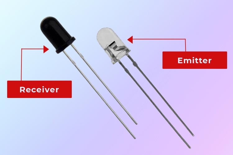
IR sensor is the reason why the bot is able to follow the line. You can also use the IR sensor module but here we’ve built the IR sensor. Building the IR sensor is simple once you understand the working of it. The IR sensor basically consists of Infrared Transmitter (IR LED) and IR Receiver (Photodiode). Sometimes, IR LED and Photodiode together is called OptoCoupler or PhotoCoupler. The IR Transmitter LED, as its name suggests, transmits IR light. Infrared transmitters could be of different types based on their wavelengths, output power, and response time. Similar to this, there are varieties of IR receivers based on wavelength, voltage, packaging, and other factors. The wavelength of the receiver should match that of the transmitter when utilized in an infrared transmitter-receiver combo. The photo of the IR transmitter and receiver LEDs is shown below.
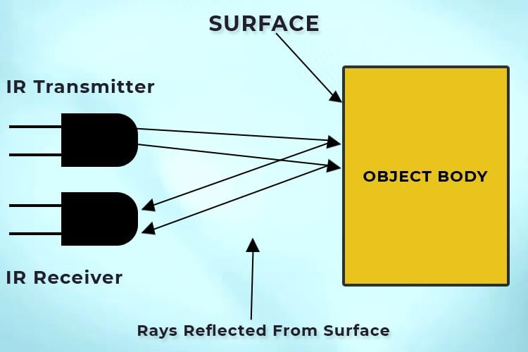
When the IR LED transmits an IR ray if any object is present to block the IR rays, the surface of the object will reflect IR rays and the IR photodiode is sensitive to these rays. The IR photodiode receives these reflected IR rays and hence, the resistance and output voltages vary accordingly. Using this variation of output voltage (or resistance of photodiode) we can build the logical circuit. This is the basic working principle of the IR sensor; we will use this to detect the presence of the line. Now, IR rays are reflected when a white surface is present but a black surface will absorb. Hence, we will be able to detect where a black line is present and we can build a logical circuit to follow this line. The working principle of the IR transmitter and receiver is as shown in the diagram.
(Tip: to check if the IR transmitter is transmitting, use the camera (mobile phone camera will also do) to see the IR transmitter. You will see a purple glow at the center of the IR LED.)
Working of L293D Motor Driver IC
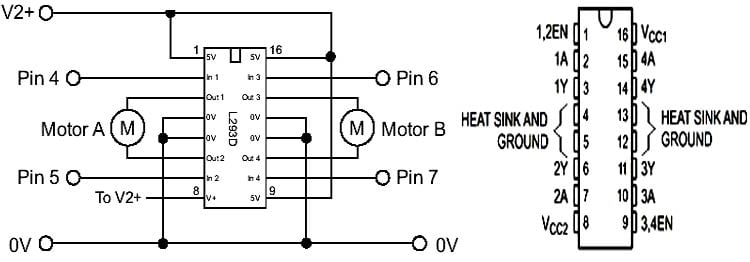
L293D is a motor driver IC. It’s used to drive the motors (hence the wheel of the bot). As shown in the pinout of the L293D IC, it can control two motors. It can change the speed of the motors based on the current supplied to the motors; it can control the direction of the motors based on the input; it can also start or stop the motors.
Circuit Diagram for Building a Line Follower Robot without a Microcontroller
Complete schematic for Line Follower robot using L293D and IR sensors are given below:

As you can see, we have divided the black line follower robot circuit into three sections, out of the two are for building IR sensors and one for building the controller circuit using L293D motor driver IC.
Building IR Sensor with LM358
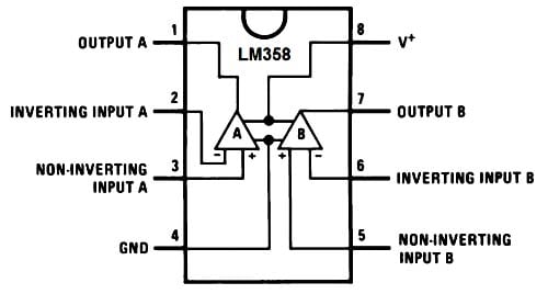
The pinout of LM358 and the circuit connections of the IR sensor are as shown below. We’re using a single LM358 IC to control both the IR sensors. LM358 is powered up using VCC and GND pins which are 8 and 4 respectively. LM358 is an Op-Amp comparator IC that gives a high output (VCC, in our case, 9V). The photodiode is reverse biased and a voltage divider is created using a 100k resistor and fed as input to the inverting terminal. The other voltage divider is created using a 10k preset and given as input to a non-inverting pin, pin 3 of the comparator. The IR LED is powered up by forward biasing it using VCC and GND. Pin 1 is output so we connect LED with current limiting resistor and take the output of the sensor from here to feed as the input for the motor driver.
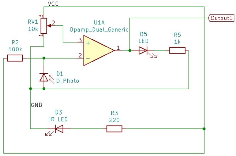
To sum up the connection, we know that the voltage and resistance of the photodiode changes based on whether there is a black or white surface present. This voltage is used to compare with a reference voltage, obtained by the preset, to give high or low voltage. The output is indicated using the LED.
L293D Motor Controller Circuit
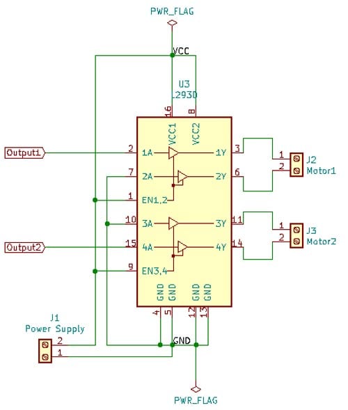
Pins 4, 5, 13, and 12 are shorted and connected to Ground. Pin 16 is the VCC pin. These two pins power the IC. Pin 8 is the VCC, the voltage with which the motors run, should be given here. Since we’re using a 9V battery, we’re going to short both the VCC pins (pin 8 and pin 16) and directly give it to 9V. Pin 1 and pin 9 are Enable pins for respective motors; for our connection, we need the motor to run as soon as it gets input from the IR sensor, so we’ll connect the enable pin to high (short it with VCC). Pins 3 and 6 should go to one motor and pins 14 and 11 should go to another motor. Now, we have two pins for sensor output. This is used to run the motor in a forward or reverse direction. Since our bot is going to move only in the forward direction, we can connect pin 7 and 10 to the ground and give the IR sensor output to pins 2 and 4.
To sum up the connections, the bot moves forward when there’s high input from the IR sensor. When there is a white surface under the bot, the IR sensor gives high output hence the motors turn forward. If both the IR sensors come across the black surface, it gives low output and hence the motor won’t run. At this point, the bot stops moving forward. But if only one of the IR sensors comes across the black surface, that sensor gives low output whereas the other IR sensor, which will be on the white surface will give high output hence that side motor will still be turning and hence the bot makes the turn.
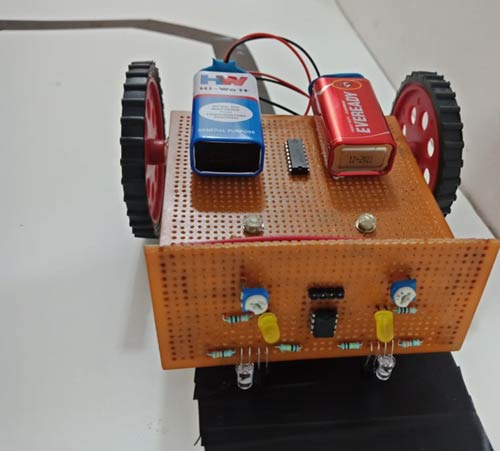
Assembling the Line Follower Robot
Once we have understood the connection of all the components, we can start assembling our Line following robot. To make this robot, first, we need a robot chassis. Here we used a simple readymade robot chassis. Then, we placed the BO motors with the IR circuit and controller circuit to the chassis with the help of some hot glue as shown in the image below.
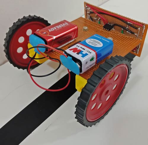
To power the bot, Lithium-Ion batteries (like 18650) along with a boost converter (to convert 3.7V to 5V) are preferred since a simple 9V battery can’t run the bot. But by using 18650, charging circuits also should be included which makes the circuit a little complex. Hence, we’ve used two 9V batteries in parallel combination here. A single 9V battery won’t output enough power to drive both the motors and the IR circuit; hence a parallel combination has to be used. The L293D and IC 358 both can take input voltage up to 9V, hence it is used here. If one is using higher than 9V to power the circuit, check the datasheet of L293D and IC 358 for input voltage (because higher voltages might damage the IC).
Testing and Calibration
We have assembled the robot and as it doesn’t require any code, so it’s time to see it in action. For that all we need to do is place the robot on top of the black line and see it in action.
Advantages of designing Line Following bot without microcontroller
- We learn designing basic logic circuits and it gives us the understanding of the working of microcontroller logic.
- We build the IR sensor and understand its working too.
- Without microcontroller, the cost of the overall project is reduced.
- No programming is required as there is no microcontroller.
- The circuit is simple and helps strengthen basic electronics concepts.
Limitations of designing Line Following bot without microcontroller
- The bot can’t make 90 degree turns.
- The bot runs in jerk motions instead of smooth motion (this could be fixed using PID controllers along with microcontroller).
- The bot stops moving when both the sensor detects the black line.

What did you use to reduce motor speed so it doesn't speed past the line when sensor is high