

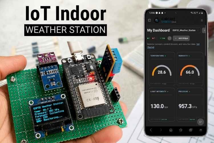
"Is it going to rain, or should I leave the windows open?" we would have asked ourselves numerous times. Now the weather is clear, but sometimes the rain will suddenly start pouring. The standard weather forecast application may give you accurate forecasts near the airport or other places, which are kilometres away from us, but it will not give us accurate forecasts near our house.
To overcome this problem, in this tutorial we are going to build an IoT indoor weather monitoring system by ourselves. This DIY IoT indoor weather monitoring system senses the weather parameters and displays the data on an OLED and also in CircuitDigest Cloud to monitor the weather from your phone anywhere. It also has an alerting system: if the sensed parameter exceeds the threshold, it would alert us by SMS to your Mobile phone. Here is another IoT based weather monitoring using Arduino where the microcontroller hosts a web server to monitor the weather.
Table of Contents
How This IoT Weather Monitoring System Project Works
This IoT indoor weather monitoring station monitors the surrounding weather parameters like temperature, pressure, humidity, and light intensity. Every 2 seconds, all sensor readings are processed on the ESP32, and the results are displayed on an OLED display. Every 5 seconds, the sensor data is sent to the cloud. When the temperature reaches a threshold of 40°C, it will trigger an SMS to your phone to alert you once, and the buzzer beeps. But the buzzer will only stop when the temperature reaches 38°C. It also has automatic contrast control for the OLED; if the surrounding lux is higher, the brightness of the OLED is higher and vice versa. We can ask AI assistance about our device, like
1. When was 40°C reached previously
2. What are the current readings in all four parameters?
Here is another Desktop weather station where we showcased how it is integrated with an E-ink display. You can also check out similar AI based projects done previously.
Components Required for This IoT Indoor Weather Monitoring System
Below is the list of components required to build this project with their description.
| S.no | Components | Specification | Quantity |
| 1. | Microcontroller | ESP32 Dev Kit | 1 |
| 2. | Temperature and humidity sensor | DHT-11 | 1 |
| 3. | Pressure sensor | BMP280 | 1 |
| 4. | Light index sensor | BH1750 | 1 |
| 5. | Buzzer | 3.3V active buzzer | 1 |
| 6. | OLED | SSD1306 | 1 |
IoT Indoor Weather Station Wiring Diagram
Below is the IoT Indoor weather station wiring diagram

The wiring of this Indoor monitoring weather station is quite simple. SCL/SCK pin of the BH1750 sensor, BMP280 sensor and OLED display is connected to GPIO 22 of the ESP32. The SDA pin of the BH1750 sensor, BMP280 sensor and OLED display is connected to GPIO 21 of the ESP32. The GND pin of the DHT11 sensor, buzzer, BH1750 sensor, BMP280 sensor and OLED display is commonly grounded and connected to the GND pin of the ESP32. The VCC/3.3V pin of the DHT11 sensor, buzzer, BH1750 sensor, BMP280 sensor and OLED display is connected to the 3.3 V pin of the ESP32.
The ADDR pin of the BH1750 sensor and the SDO pin of the BMP280 sensor are connected to the GND pin of the ESP32. The CSB pin of the BMP280 is connected to the 3.3 V pin of ESP32. The data pin of the DHT11 sensor is connected to GPIO 23, and the data pin of the buzzer is connected to GPIO 4. You can also check out similar ESP32 Projects and IoT projects done previously here at Circuit Digest.
Step-by-Step CircuitDigest Cloud Setup for IoT Live Indoor Weather Station Monitoring
Step-by-Step guide for IoT Indoor weather station in CircuitDigest Cloud is listed below. This makes monitoring the weather station on our smartphone easier.
Step 1⇒Sign up / Login
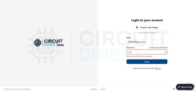
Sign up or login into your account CircuitDigest Cloud by giving valid email and password.
Step 2⇒ Adding New Device
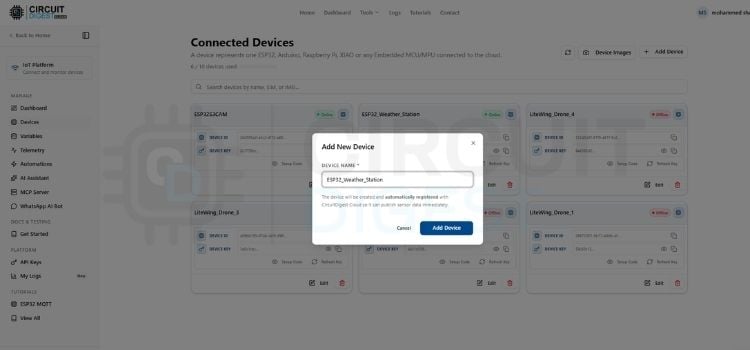
After logging in, click the device option on the left side of the website, click Add New Device and give the name you want to give your project; for us, we have given ESP32_Weather_Station. You can give the name you want to display for this device and click the Add Device button in blue colour.
Step 3⇒Adding New Variables
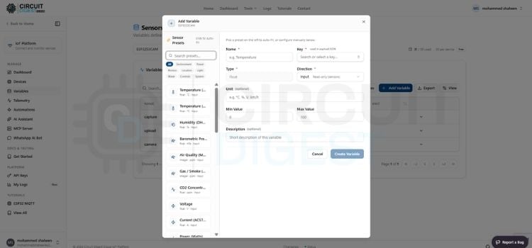
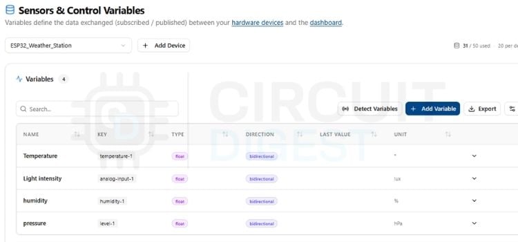
After creating a new device, click Variables on the left side of the website. Now select the device you created from the drop-down option. Click the Add Variable option. You will see a pop-up in the name section, first we will create a variable for temperature. Give the name you want to display for the variable; we have named it temperature. Select the key you want for this variable; we have selected temperature-1. Set the direction as bidirectional, set the unit as °C, and press Create Variable. The variable will be created. Do the same for 3 more variables and change the units as per the variable we are measuring.
Step 4⇒Variable List
These four variable names allow us to choose the key we want: temperature-1 for the temperature key, analogue-input-1 for the light intensity key, humidity-1 for the humidity key, and level-1 for the pressure key.
Step 5⇒Adding Widget
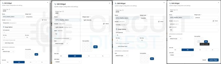
After adding the variable, click the dashboard from the left side of the website and select the device you created from the drop-down. First, we will create a widget for temperature. Click Add Widget, then click Gauge. A menu bar will pop up. Select the device you created from the drop-down, name it Temperature, set the variable as temperature-1, then set the unit as °C and click Add Widget. For temperature and humidity, place a gauge widget; for light intensity and pressure, place a value display widget. Do the same for the other 3 widgets, but select the proper variable for the widget placed. Now the dashboard setup is over.
Step 6⇒SMS API Integration
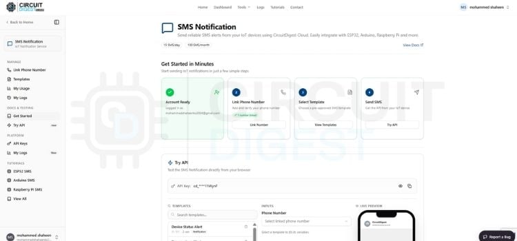
Open the CircuitDigest Cloud website and scroll down to the API section. Log in and link your number to the API to receive SMS alerts from the weather station.
IoT Indoor Weather Station Using CircuitDigest Cloud | Live Demo
Watch the ESP32-based IoT Indoor Weather Station monitor temperature, humidity, and pressure in real time using CircuitDigest Cloud. This live demo showcases sensor data updates, Wi-Fi connectivity, and cloud dashboard visualisation working seamlessly together. Perfect for IoT enthusiasts, students, and makers who want to build a smart indoor climate monitoring system using ESP32.
IoT Indoor Weather Monitoring System Code Explanation
The code is written in Arduino IDE for a real-time weather monitoring system using an ESP32 microcontroller.
// ---------------- WiFi -------------------------------------------------------
const char *ssid     = "XXXXXXX";       // <-- your WiFi SSID
const char *password = "XXXXXXX";      // <-- your WiFi password
// ---------------- CircuitDigestCloud (for the gauge) -------------------------
const char *DEVICE_ID        = "XXXXXXX"; // Physical Device ID
const char *CONNECTION_KEY   = "XXXXXXX";     // Connection Key
const char *TEMPERATURE_SLOT = "temperature-1"; // slot key from dashboard
const char *HUMIDITY_SLOT    = "humidity-1"; // slot key from dashboard (gauge widget)
const char *PRESSURE_SLOT    = "level-1"; // slot key from dashboard (value widget)
CircuitDigestCloud cd; // no constructor args — library owns its own TLS client
// ---------------- SMS (Circuit Digest Cloud SMS API) --------------------------
const char* apiKey       = "XXXXXXX";   // Your API key from Circuit Digest Cloud website
const char* templateID   = "102";            // Your SMS template ID
const char* mobileNumber = "XXXXXXXXXX";   // Recipient number with country code
char        var1[8]      = "0";              // Template variable: temperature at trigger time
char        var2[8]      = "0";              // Template variable: humidity at trigger time
Network Credentials & Cloud Authentication
This block stores the credentials needed to connect the hardware to the local Wi-Fi and the cloud like Wi-Fi name, password, device ID, connection key, and API key.
Wire.begin(21, 22);    // SDA on GPIO 21, SCL on GPIO 22 (ESP32 Defaults)
Wire.setClock(100000); // Set standard 100kHz I2C clock speed
I2C Communications Bus Initialization
This line ensures that the BMP280, BH1750, and OLED all share the same physical wire path. It ensures that communication packets do not overlap or drop out.
// Oldest sample currently in the buffer
int oldestIndex = (pressureHistoryIndex + PRESSURE_HISTORY_LEN - pressureHistoryCount) % PRESSURE_HISTORY_LEN;
float oldest = pressureHistory[oldestIndex];
float trend = pressureHpa - oldest; // hPa change over the buffered window
if (trend >= 1.5) {
 forecastText = "Rising";
} else if (trend <= -1.5) {
 forecastText = "Falling";
} else {
 forecastText = "Steady";
}
Barometric Forecast Processing
This algorithm measures the change in barometric pressure rather than simply measuring current pressure. A drop of 1.5 hPa or more in 3 hours is a good indicator of low-pressure fronts, which allows the weather station to forecast rainstorms.
float clamped = constrain(luxLevel, LUX_MIN_FOR_SCALE, LUX_MAX_FOR_SCALE);
uint8_t contrast = map((long)clamped, (long)LUX_MIN_FOR_SCALE, (long)LUX_MAX_FOR_SCALE,
                       OLED_CONTRAST_MAX, OLED_CONTRAST_MIN);
display.ssd1306_command(SSD1306_SETCONTRAST);
display.ssd1306_command(contrast);
Dynamic Screen Contrast Controller
This block is used to control the contrast of the OLED using the Light intensity sensor lux data.
// --- SMS alert logic with hysteresis ---
if (!alertActive && temperature >= SMS_TRIGGER_TEMP) {
 sendSMS();
 alertActive = true; // Locks the alert state
} else if (alertActive && temperature < SMS_RESET_TEMP) {
 alertActive = false; // Re-arms the system for the next trip
 smsStatusText = "Monitoring...";
 updateDisplay();
}
SMS Alert Engine
This section sets the SMS alert threshold; if the temperature is reached above the threshold, the Buzzer and SMS alert are triggered. The SMS alert is triggered once after reaching the threshold, but the buzzer will make sound until the temperature reaches the reset temperature value.
if (now - lastPublish >= PUBLISH_INTERVAL) {
lastPublish = now;
cd.publish({{TEMPERATURE_SLOT, temperature}, {LUX_SLOT, luxLevel}, {HUMIDITY_SLOT, humidity}, {PRESSURE_SLOT, pressureHpa}});
}
Multi-Variable MQTT Publishing
This section makes the sensor data push every 5 seconds to the cloud. You can also check out similar Home Automation Projects done previously here at Circuit Digest.
Output
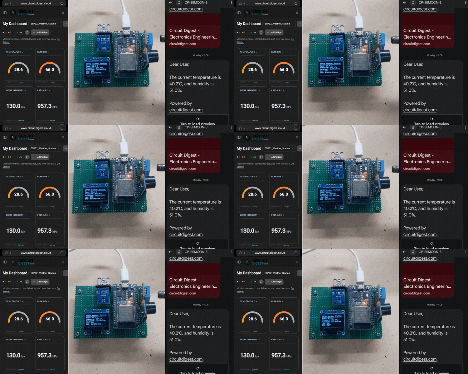
This finished IoT indoor weather monitoring system project bridges physical hardware with the cloud to track your room's climate in real time. This weather station integrates physical hardware with the cloud to monitor the weather of the surrounding space. It shows the sensor readings of temperature, pressure, and humidity on the OLED and in the CircuitDigest Cloud. If the threshold of 40°C is reached, the buzzer will make an alert, and an SMS alert is sent to the registered phone number in the SMS API in CircuitDigest Cloud. You can also check out similar CircuitDigest Cloud Projects done previously here at Circuit Digest.
IoT Weather Monitoring System GitHub
Explore open-source IoT weather monitoring system projects on GitHub to learn how developers build real-time environmental monitoring solutions. Find source code, circuit diagrams, and documentation to kickstart your own DIY weather station.


Troubleshooting
1: What should you do if the buzzer does not sound during an alert?
Fix: Make sure you are using a 3.3V active buzzer module and connecting it to GPIO 4.
2: The ESP32 is powered on, but it cannot connect to Wi-Fi.
Fix: Check that you have the right credentials in the network settings at the top of the sketch.
3: What should you check if the emergency SMS alert is not being sent to your phone?
Fix: Verify that your mobile number is correctly registered in the code with the proper country code prefix. Additionally, ensure your unique API key and Template ID match your account configuration on the Circuit Digest Cloud SMS API gateway.
4: Where can I view the real-time operational status of my device on the web platform?
Fix: In the CircuitDigest Cloud website, go to the dashboard, select the device you created, and you will see your gauges and value display you created.
5: What if the OLED screen shows blank or frozen text values after system boot?
Fix: Ensure the shared I2C bus wiring is connected to the correct pins (GPIO 21 for SDA and GPIO 22 for SCL).
Explore More IoT Weather Station Projects
Discover a collection of IoT projects, including DIY weather stations, real-time weather monitoring for agriculture, and smart home automation systems. These tutorials provide complete circuit diagrams, source code, and step-by-step instructions to help you build connected IoT solutions using ESP8266, ESP32, sensors, and cloud platforms.
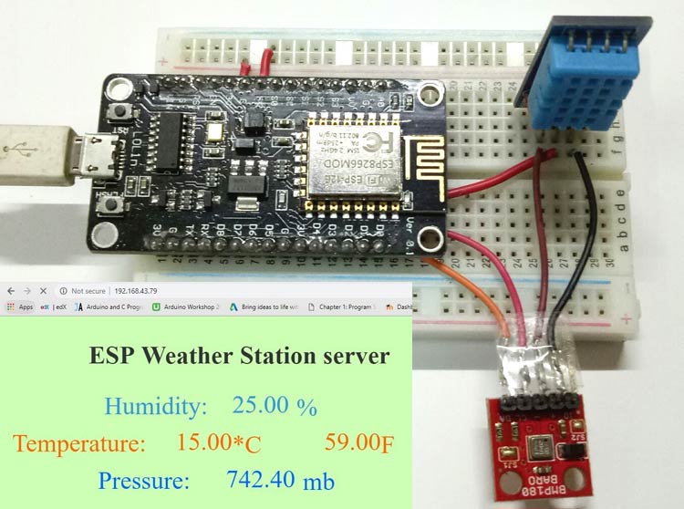
IoT Weather Station using NodeMCU: Monitoring Humidity, Temperature and Pressure over Internet
In this project, we will measure Humidity, temperature, and Pressure parameters and display them on the web server, which makes it an IoT-based weather station where the weather conditions can be monitored from anywhere using the Internet.

ESP32-S3 Box 3 Smart Weather Station: Real-Time Field Monitoring for Farmers from Home
This project is an IoT-based weather station tailored for farmers to monitor their fields remotely. It collects comprehensive environmental data from Home, including wind speed, wind direction, temperature, humidity, pressure, gas levels, altitude, and rainfall.

This project showcases an IoT Weather Station built using the Arduino Uno R4 Wi-Fi, designed to monitor and report various environmental parameters. Utilising multiple sensors—including the DHT22 for temperature and humidity, the BMP180 for atmospheric pressure, an anemometer for wind speed, a wind vane for wind direction, and a rain gauge for measuring rainfall—this station provides comprehensive weather data.
Complete Project Code
// Copyright (c) 2026 Circuit Digest
// SPDX-License-Identifier: MIT
//
// DHT11 -> CircuitDigestCloud gauge display + SMS alert at 40°C
// Board target: ESP32
// DHT11 data pin: GPIO 23
//
// Library: CircuitDigestCloud v2.x (manages WiFi + TLS internally —
// no WiFi.begin() or WiFiClientSecure needed in this sketch).
//
// - Publishes "temperature" to the dashboard's temperature-1 slot,
//   "humidity" to humidity-1 (gauge widget), "light intensity" to
//   analog-input-1, and "pressure" to level-1 (value widget) every 5s.
// - SMS alert message reports both live temperature and humidity.
// - Sends one SMS alert when temperature >= 40°C.
// - Won't send another SMS until temperature drops back below 38°C
//   (hysteresis, so you don't get spammed while it hovers around 40).
// - 0.96" I2C SSD1306 OLED shows live temperature + whether the SMS
//   alert has been sent. Wiring: SDA -> GPIO21, SCL -> GPIO22 (ESP32
//   default I2C pins), VCC -> 3.3V, GND -> GND.
// - BH1750 ambient light sensor (I2C, shares SDA/SCL with the OLED)
//   publishes lux to the "Light intensity" widget (analog-input-1),
//   shows the reading on the OLED, and auto-adjusts OLED brightness
//   (dim in the dark, bright in daylight).
// - BMP280 pressure sensor (I2C, same shared bus) tracks barometric
//   pressure trend over ~3 hours and shows a simple weather forecast
//   ("Rising", "Falling", "Steady") on the OLED.
// - Buzzer (GPIO4) sounds continuously while temperature >= 40°C OR
//   the forecast reads "Falling" (rain likely). Turns off once both
//   conditions clear.
//
// Requires libraries: "Adafruit SSD1306", "Adafruit GFX Library",
// "BH1750" by Christopher Laws, and "Adafruit BMP280 Library"
// (install all via Arduino Library Manager).
#include <WiFi.h>          // only used here for the plain SMS HTTP request
#include <DHT.h>
#include <DHT_U.h>
#include <CircuitDigestCloud.h>
#include <Wire.h>
#include <Adafruit_GFX.h>
#include <Adafruit_SSD1306.h>
#include <BH1750.h>
#include <Adafruit_BMP280.h>
// ---------------- Sensor ----------------------------------------------------
#define Temp_SensorPin 23
DHT_Unified dht(Temp_SensorPin, DHT11);
float temperature = 0.0;
float humidity = 0.0; // DHT11 measures both temp and humidity, no extra hardware needed
// ---------------- Buzzer ------------------------------------------------------
#define BUZZER_PIN 4   // active buzzer module signal pin
// Some active buzzer modules turn ON when the signal pin is HIGH, others turn
// ON when it's LOW. If your buzzer sounds immediately on boot (or never turns
// off), flip this constant to the other value.
#define BUZZER_ON_LEVEL  LOW   // <-- try LOW first (common for many modules); change to HIGH if wrong
#define BUZZER_OFF_LEVEL (BUZZER_ON_LEVEL == HIGH ? LOW : HIGH)
bool buzzerOn = false;
// ---------------- OLED (0.96" SSD1306, I2C) ----------------------------------
#define SCREEN_WIDTH   128
#define SCREEN_HEIGHT  64
#define OLED_RESET     -1     // no dedicated reset pin
#define OLED_ADDRESS   0x3C   // most 0.96" SSD1306 modules use 0x3C (some use 0x3D)
Adafruit_SSD1306 display(SCREEN_WIDTH, SCREEN_HEIGHT, &Wire, OLED_RESET);
String smsStatusText = "Monitoring...";
// ---------------- BH1750 (ambient light) --------------------------------------
BH1750 lightMeter;                 // default I2C address 0x23 (ADDR pin low/unconnected)
float luxLevel = 0.0;
const char *LUX_SLOT = "analog-input-1"; // slot key from dashboard ("Light intensity" widget)
// OLED brightness auto-adjust range (contrast 0-255)
// Lower lux -> higher contrast (brighter screen); higher lux -> lower contrast.
const float   LUX_MIN_FOR_SCALE = 0.0;    // lux at/below this -> screen at max brightness
const float   LUX_MAX_FOR_SCALE = 1000.0; // lux at/above this -> screen at min brightness
const uint8_t OLED_CONTRAST_MIN = 10;     // dimmest screen setting
const uint8_t OLED_CONTRAST_MAX = 255;    // brightest screen setting
// ---------------- BMP280 (barometric pressure -> weather forecast) -----------
Adafruit_BMP280 bmp; // I2C
float pressureHpa = 0.0;
String forecastText = "Collecting";
// Rolling pressure history for trend detection.
// PRESSURE_HISTORY_LEN samples spaced PRESSURE_SAMPLE_INTERVAL apart cover
// a ~3 hour window, which is the standard window for barometric forecasting.
const int PRESSURE_HISTORY_LEN = 6;
const unsigned long PRESSURE_SAMPLE_INTERVAL = 30UL * 60UL * 1000UL; // 30 min
float pressureHistory[PRESSURE_HISTORY_LEN];
int   pressureHistoryCount = 0;   // how many slots are filled so far
int   pressureHistoryIndex = 0;   // next slot to write (circular buffer)
unsigned long lastPressureSample = 0;
// ---------------- WiFi -------------------------------------------------------
const char *ssid     = "XXXXXXXXXX";       // <-- your WiFi SSID
const char *password = "XXXXXXXXXX";      // <-- your WiFi password
// ---------------- CircuitDigestCloud (for the gauge) -------------------------
const char *DEVICE_ID        = "XXXXXX-XXXXXX-XXXXXX"; // your Physical Device ID from CircuitDigest Cloud
const char *CONNECTION_KEY   = "XXXXXX-XXXXXX";     // your device Connection Key from CircuitDigest Cloud
const char *TEMPERATURE_SLOT = "temperature-1";                        // slot key from dashboard
const char *HUMIDITY_SLOT    = "humidity-1";                           // slot key from dashboard (gauge widget)
const char *PRESSURE_SLOT    = "level-1";                              // slot key from dashboard (value widget)
CircuitDigestCloud cd; // no constructor args — library owns its own TLS client
// ---------------- SMS (Circuit Digest Cloud SMS API) --------------------------
const char* apiKey       = "xxxxxxxxxxxxxxx";   // Your API key from Circuit Digest Cloud website
const char* templateID   = "102";            // Your SMS template ID
const char* mobileNumber = "xxxxxxxxxxxx";   // Recipient number with country code
char        var1[8]      = "0";              // Template variable: temperature at trigger time
char        var2[8]      = "0";              // Template variable: humidity at trigger time
// ---------------- Alert thresholds -------------------------------------------
const float SMS_TRIGGER_TEMP = 40.0;  // send SMS at/above this
const float SMS_RESET_TEMP   = 38.0;  // must drop below this before next SMS can fire
bool alertActive = false;             // true = SMS sent, waiting for reset
// ---------------- Timers ------------------------------------------------------
unsigned long lastSensorRead = 0;
const unsigned long SENSOR_INTERVAL = 2000;   // read DHT11 every 2s
unsigned long lastPublish = 0;
const unsigned long PUBLISH_INTERVAL = 5000;  // push to gauge every 5s
// ---------------------------------------------------------------------------
void read_temperature() {
 sensors_event_t event;
 dht.temperature().getEvent(&event);
 if (!isnan(event.temperature)) {
   temperature = event.temperature;
   Serial.print("Temperature: ");
   Serial.println(temperature);
 } else {
   Serial.println("DHT11 read failed!");
 }
 sensors_event_t humidityEvent;
 dht.humidity().getEvent(&humidityEvent);
 if (!isnan(humidityEvent.relative_humidity)) {
   humidity = humidityEvent.relative_humidity;
   Serial.print("Humidity: ");
   Serial.print(humidity);
   Serial.println(" %");
 } else {
   Serial.println("DHT11 humidity read failed!");
 }
 updateDisplay();
}
// ---------------------------------------------------------------------------
void read_lux() {
 float reading = lightMeter.readLightLevel();
 if (reading >= 0) { // BH1750 returns a negative value on read error
   luxLevel = reading;
   Serial.print("Light: ");
   Serial.print(luxLevel);
   Serial.println(" lx");
 } else {
   Serial.println("BH1750 read failed! Re-initializing sensor...");
   if (lightMeter.begin(BH1750::CONTINUOUS_HIGH_RES_MODE, 0x23, &Wire)) {
     Serial.println("BH1750 re-init OK.");
   } else {
     Serial.println("BH1750 re-init failed, will retry next cycle.");
   }
 }
 setOledBrightness();
 updateDisplay();
}
// ---------------------------------------------------------------------------
void setOledBrightness() {
 // Map lux -> OLED contrast, INVERTED: dimmer room = brighter screen,
 // brighter room = dimmer screen.
 float clamped = constrain(luxLevel, LUX_MIN_FOR_SCALE, LUX_MAX_FOR_SCALE);
 uint8_t contrast = map((long)clamped, (long)LUX_MIN_FOR_SCALE, (long)LUX_MAX_FOR_SCALE,
                         OLED_CONTRAST_MAX, OLED_CONTRAST_MIN); // note: swapped from before
 display.ssd1306_command(SSD1306_SETCONTRAST);
 display.ssd1306_command(contrast);
}
// ---------------------------------------------------------------------------
void read_pressure() {
 float reading = bmp.readPressure(); // returns Pa
 if (!isnan(reading) && reading > 0) {
   pressureHpa = reading / 100.0; // Pa -> hPa
   Serial.print("Pressure: ");
   Serial.print(pressureHpa);
   Serial.println(" hPa");
 } else {
   Serial.println("BMP280 read failed!");
   return;
 }
 // Sample into the trend-history buffer every 30 min
 unsigned long now = millis();
 if (now - lastPressureSample >= PRESSURE_SAMPLE_INTERVAL || lastPressureSample == 0) {
   lastPressureSample = now;
   pressureHistory[pressureHistoryIndex] = pressureHpa;
   pressureHistoryIndex = (pressureHistoryIndex + 1) % PRESSURE_HISTORY_LEN;
   if (pressureHistoryCount < PRESSURE_HISTORY_LEN) pressureHistoryCount++;
   updateForecast();
 }
}
// ---------------------------------------------------------------------------
void updateForecast() {
 if (pressureHistoryCount < 2) {
   forecastText = "Collecting";
   return;
 }
 // Oldest sample currently in the buffer
 int oldestIndex = (pressureHistoryIndex + PRESSURE_HISTORY_LEN - pressureHistoryCount) % PRESSURE_HISTORY_LEN;
 float oldest = pressureHistory[oldestIndex];
 float trend = pressureHpa - oldest; // hPa change over the buffered window
 String direction;
 if (trend >= 1.5) {
   direction = "Rising";
 } else if (trend <= -1.5) {
   direction = "Falling";
 } else {
   direction = "Steady";
 }
 forecastText = direction;
}
// ---------------------------------------------------------------------------
void updateBuzzer() {
 // Sound the buzzer if either condition is true:
 //  - alertActive is true (same 40°C trigger / 38°C reset hysteresis as the SMS), OR
 //  - the pressure trend shows "Falling" (rain likely)
 bool shouldSound = alertActive || (forecastText == "Falling");
 if (shouldSound && !buzzerOn) {
   digitalWrite(BUZZER_PIN, BUZZER_ON_LEVEL);
   buzzerOn = true;
   Serial.println("Buzzer ON");
 } else if (!shouldSound && buzzerOn) {
   digitalWrite(BUZZER_PIN, BUZZER_OFF_LEVEL);
   buzzerOn = false;
   Serial.println("Buzzer OFF");
 }
}
// ---------------------------------------------------------------------------
void updateDisplay() {
 display.clearDisplay();
 // Title
 display.setTextSize(1);
 display.setTextColor(SSD1306_WHITE);
 display.setCursor(0, 0);
 display.println("ESP32 Weather Station");
 display.drawLine(0, 10, SCREEN_WIDTH - 1, 10, SSD1306_WHITE);
 // Temperature
 display.setCursor(0, 14);
 display.print("Temp: ");
 display.print(temperature, 1);
 display.print(" C");
 // Pressure
 display.setCursor(0, 24);
 display.print("Pressure: ");
 display.print(pressureHpa, 0);
 display.print(" hPa");
 // Forecast
 display.setCursor(0, 34);
 display.print("Forecast: ");
 display.print(forecastText);
 // Lux reading
 display.setCursor(0, 44);
 display.print("Lux: ");
 display.print(luxLevel, 0);
 // SMS alert status line at the bottom
 display.setCursor(0, 54);
 display.print("SMS: ");
 display.print(smsStatusText);
 display.display();
}
// ---------------------------------------------------------------------------
void sendSMS() {
 if (WiFi.status() != WL_CONNECTED) {
   Serial.println("WiFi not connected, can't send SMS!");
   smsStatusText = "Failed (No WiFi)";
   updateDisplay();
   return;
 }
 WiFiClient client; // plain HTTP client, separate from CircuitDigestCloud's own MQTT/TLS connection
 String apiUrl = "/api/v1/send_sms?ID=" + String(templateID);
 Serial.print("Connecting to SMS server...");
 if (!client.connect("www.circuitdigest.cloud", 80)) {
   Serial.println("Connection to SMS server failed!");
   smsStatusText = "Failed (No Conn)";
   updateDisplay();
   return;
 }
 Serial.println("connected!");
 dtostrf(temperature, 4, 1, var1); // var1 -> current temperature, e.g. "40.2"
 dtostrf(humidity, 4, 1, var2);    // var2 -> current humidity, e.g. "43.2"
 String payload = "{\"mobiles\":\"" + String(mobileNumber) +
                   "\",\"var1\":\"" + String(var1) +
                   "\",\"var2\":\"" + String(var2) + "\"}";
 client.println("POST " + apiUrl + " HTTP/1.1");
 client.println("Host: www.circuitdigest.cloud");
 client.println("Authorization: " + String(apiKey));
 client.println("Content-Type: application/json");
 client.println("Content-Length: " + String(payload.length()));
 client.println();
 client.println(payload);
 int responseCode = -1;
 while (client.connected() || client.available()) {
   if (client.available()) {
     String line = client.readStringUntil('\n');
     Serial.println(line);
     if (line.startsWith("HTTP/")) {
       responseCode = line.substring(9, 12).toInt();
     }
     if (line == "\r") break;
   }
 }
 if (responseCode == 200) {
   Serial.println("SMS sent successfully!");
   smsStatusText = "SENT!";
 } else {
   Serial.print("Failed to send SMS. Error code: ");
   Serial.println(responseCode);
   smsStatusText = "Failed (" + String(responseCode) + ")";
 }
 updateDisplay();
 client.stop();
}
// ---------------------------------------------------------------------------
void setup() {
 Serial.begin(115200);
 delay(200);
 dht.begin();
 // ---- Buzzer init ----
 pinMode(BUZZER_PIN, OUTPUT);
 digitalWrite(BUZZER_PIN, BUZZER_OFF_LEVEL); // start silent
 // ---- OLED init ----
 Wire.begin(21, 22); // SDA, SCL (ESP32 default I2C pins) — shared by OLED and BH1750
 if (!display.begin(SSD1306_SWITCHCAPVCC, OLED_ADDRESS)) {
   Serial.println("SSD1306 OLED not found! Check wiring/address.");
 } else {
   display.clearDisplay();
   display.setTextSize(1);
   display.setTextColor(SSD1306_WHITE);
   display.setCursor(0, 20);
   display.println("Starting up...");
   display.display();
 }
 // ---- BH1750 init (retry a few times — it occasionally fails on the
 //      first attempt right after power-up or while WiFi is starting) ----
 Wire.setClock(100000); // 100kHz — more reliable than 400kHz on a shared bus with long wires
 bool bh1750Ok = false;
 for (int attempt = 1; attempt <= 5 && !bh1750Ok; attempt++) {
   bh1750Ok = lightMeter.begin(BH1750::CONTINUOUS_HIGH_RES_MODE, 0x23, &Wire);
   if (!bh1750Ok) {
     Serial.print("BH1750 init attempt ");
     Serial.print(attempt);
     Serial.println(" failed, retrying...");
     delay(300);
   }
 }
 if (!bh1750Ok) {
   Serial.println("BH1750 not found after 5 attempts! Check wiring/address.");
 }
 // ---- BMP280 init (try 0x76 then 0x77, retry a few times) ----
 bool bmpOk = false;
 for (int attempt = 1; attempt <= 5 && !bmpOk; attempt++) {
   bmpOk = bmp.begin(0x76) || bmp.begin(0x77);
   if (!bmpOk) {
     Serial.print("BMP280 init attempt ");
     Serial.print(attempt);
     Serial.println(" failed, retrying...");
     delay(300);
   }
 }
 if (bmpOk) {
   bmp.setSampling(Adafruit_BMP280::MODE_NORMAL,
                    Adafruit_BMP280::SAMPLING_X2,   // temperature oversampling
                    Adafruit_BMP280::SAMPLING_X16,  // pressure oversampling
                    Adafruit_BMP280::FILTER_X16,
                    Adafruit_BMP280::STANDBY_MS_500);
 } else {
   Serial.println("BMP280 not found after 5 attempts! Check wiring/address.");
 }
 // ---- CircuitDigestCloud setup (drives the gauge) ----
 // begin() connects WiFi itself and starts the MQTT session — no manual
 // WiFi.begin() loop needed. It blocks until WiFi connects (default), then
 // brings up MQTT in the background.
 cd.setDebug(&Serial); // prints [CD] status lines to Serial; call before begin()
 cd.begin(ssid, password, DEVICE_ID, CONNECTION_KEY);
}
// ---------------------------------------------------------------------------
void loop() {
 cd.loop(); // keep the cloud connection alive (non-blocking)
 unsigned long now = millis();
 // --- Read DHT11 + BH1750 periodically ---
 if (now - lastSensorRead >= SENSOR_INTERVAL) {
   lastSensorRead = now;
   read_temperature();
   read_lux();
   read_pressure();
   // --- SMS alert logic with hysteresis ---
   if (!alertActive && temperature >= SMS_TRIGGER_TEMP) {
     sendSMS();
     alertActive = true; // don't fire again until it cools down
   } else if (alertActive && temperature < SMS_RESET_TEMP) {
     alertActive = false; // re-armed for next time it crosses 40°C
     smsStatusText = "Monitoring...";
     updateDisplay();
   }
   updateBuzzer(); // check after alertActive is current for this cycle
 }
 // --- Push to CircuitDigestCloud widgets periodically ---
 // Requires CircuitDigestCloud library v2.1.0+ for the batched
 // publish() overload (sends all readings in a single MQTT message).
 if (now - lastPublish >= PUBLISH_INTERVAL) {
   lastPublish = now;
   cd.publish({{TEMPERATURE_SLOT, temperature},
               {LUX_SLOT,         luxLevel},
               {HUMIDITY_SLOT,    humidity},
               {PRESSURE_SLOT,    pressureHpa}});
 }
}

Add a comment
No account needed. Your comment appears once a moderator has reviewed it.