
The PCA9306 module is a bidirectional voltage-level translator made for use with I2C bus systems. It allows devices that work at different voltage levels to communicate reliably. Older designs used separate MOSFET circuits for voltage shifting, but the PCA9306 combines all that functionality into one chip, making it more dependable and consistent. The device automatically deals with both low and high voltage sides, keeping signal levels correct on each side to safeguard sensors and controllers within their allowed voltage ranges. It keeps the standard I2C protocol working as usual, including timing, data accuracy, and bus arbitration. The module uses an open-drain output setup, which makes it compatible with many I2C devices. Once it's powered on, it starts translating signals in both directions without needing any software setup or control. Voltage level shifting using a MOSFET based approach is covered in another project
What You'll Learn:
- Total mastery over the pinout and functionality of the PCA9306 for conversion of logic levels from 5V to 3.3V.
- A step-by-step interfacing diagram for the PCA9306 to Arduino UNO.
- Working example with Arduino code that demands no level-shifter configuration.
- How to fix I2C communication problems by using various methods.
- Connection of logic level shifters in embedded projects according to best practices for maximum reliability.
Table of Contents
Understanding the PCA9306 Level Shifter Module
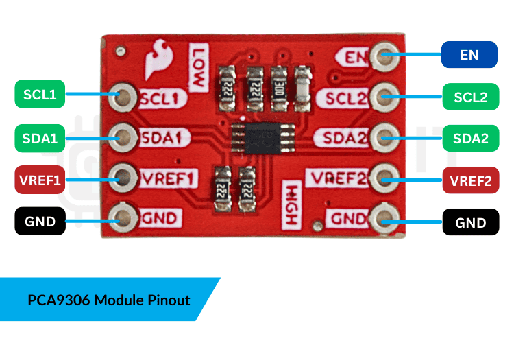
The PCA9306 IC manages both I2C signal pairs. On the low-voltage side, pull-up resistors are usually built into the board. But on the high-voltage side, the host controller is responsible for providing the necessary pull-up resistors. This arrangement helps keep the I2C signals stable and dependable on both sides of the translator. Each VREF pin sets the logic level for its own voltage. VREF1 is for the low-voltage side, and VREF2 is for the high-voltage side. The EN pin is typically connected to VREF2 via a resistor. A shared ground connection is important because it gives both sides of the translator the same reference point. Without this common ground, the translator won't work correctly, and the I2C bus might become unstable.
Interfacing the PCA9306 Module with Arduino Uno Pinout
» VREF1: Low voltage reference (3.3V) - powers the 3.3V side logic
» VREF2: High voltage reference (5V) - powers the 5V side logic
» SCL1: I2C clock line for low voltage device (3.3V)
» SDA1: I2C data line for low voltage device (3.3V)
» SCL2: I2C clock line for high voltage device (5V) - connects to Arduino A5
» SDA2: I2C data line for high voltage device (5V) - connects to Arduino A4
» GND: Common ground for both voltage domains
» EN: Enable pin - must be HIGH to activate the module
How to Interface PCA9306 with Arduino UNO
- Connect VREF1 to 3.3V and VREF2 to 5V on Arduino
- Wire SCL1/SDA1 to your 3.3V I2C device
- Connect SCL2 to A5 and SDA2 to A4 on Arduino UNO
- Link all GND pins together
- Upload your I2C code - no special programming needed for the PCA9306
PCA9306 Module Specifications
| Specification | Details |
| Low Voltage Range (VREF1) | 1.0V to 3.6V |
| High Voltage Range (VREF2) | 1.8V to 5.5V |
| I2C Speed Support | Standard (100 kHz) & Fast Mode (400 kHz) |
| Output Configuration | Open-drain bidirectional |
| Built-in Pull-up Resistors | Low-voltage side (typically 10kΩ) |
| Number of Channels | 2 (SDA and SCL) |
Components Required for Interfacing PCA9306 with Arduino Uno
The components required for interfacing the PCA306 logic level shifter module with Arduino Uno and the BMP180 Pressure sensor are shown below in the table.
| Components | Quantity | Role |
| Arduino Uno | 1 | Main Microcontroller to run code |
| PCA9306 Level Shifter Module | 1 | To work with multiple voltages |
| BMP180 | 1 | An I2C based 3.3v sensor |
| Jumper Wires | Several | Connecting the modules |
| Breadboard | 1 | For easy prototyping |
| USB Cable | 1 | Uploading code + powering ESP32 |
PCA9306 Wiring Diagram: Hardware Connection with Arduino UNO
We are using Arduino Uno to connect and get readings of the BMP180 Pressure sensor, a 3.3V sensor module which communicates using the I2C protocol.
The connection of the PCA9306 with the Arduino UNO and the BMP180 is shown in the table below.
| 3.3V Device (BMP180) | PCA9306 (Low Side) | PCA9306 (High Side) | 5V Device (Uno) |
| 3.3V | VREF1 | - | 3.3V |
| - | - | VREF2 | 5V |
| SCL | SCL1 | SCL2 | A5 |
| SDA | SDA1 | SDA2 | A4 |
| GND | GND | GND | GND |
The complete PCA9306 wiring diagram for interfacing with Arduino UNO and BMP180 sensor is illustrated below.

PCA9306 Arduino Code: Source Code Explanation
This PCA9306 Arduino code utilize the standard BMP180 library. The Arduino reads the sensor through the I2C bus. The PCA9306 sits in the middle and only shifts the voltage levels. It does not need any commands in the code.
Wire.begin() starts the I2C communication on the Arduino side.
bmp.begin() checks if the BMP180 is connected and responding. If the sensor is not found, the code stops so the user can fix the wiring.
The PCA9306 module seamlessly translates I2C signals between the 5V Arduino and the 3.3V sensor without modifying data integrity.
Inside the loop, the code reads the temperature and pressure values from the BMP180. The library handles all calculations. The PCA9306 passes the data between the Arduino and the sensor without changing anything.
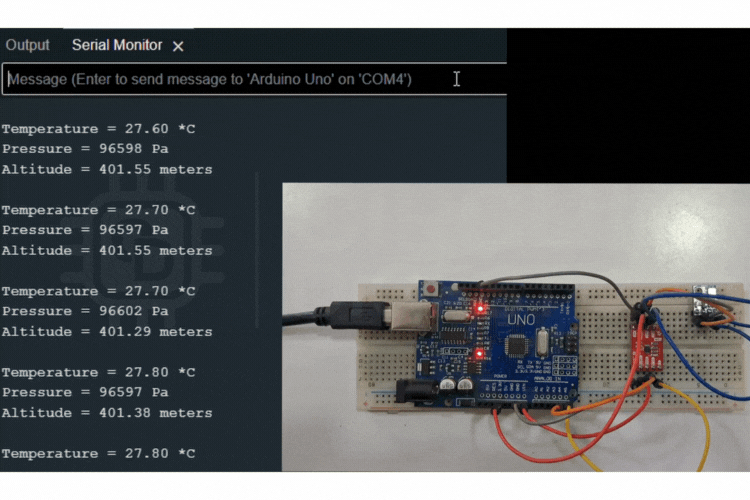
The readings are printed on the serial monitor every second. The process repeats as long as the board is powered.
Working Demonstration of PCA9306 Module
The video below shows the working of the PCA9306 Logic Level Shifter module with Arduino Uno and the BMP180 Pressure sensor.
Frequently Asked Questions About PCA9306 Arduino Integration
⇥ Does the PCA9306 need any software configuration?
No. The PCA9306 works on its own. It shifts I2C levels without any code.
⇥ Why does the module have two VREF pins?
VREF1 sets the low side voltage. VREF2 sets the high side voltage. The IC uses these to translate signals correctly.
⇥ Does the EN pin need to be tied high?
Yes. The module stays active only when EN is high. Leaving it floating can stop the level shifting.
⇥ Does the PCA9306 include pull-up resistors?
Most boards include pull-ups only on the low-voltage side. The high voltage side usually needs pull-ups from the controller.
⇥ Can the PCA9306 work with fast I2C speeds?
Yes. It supports standard and fast modes as long as the wiring is short and the bus capacitance is low.
⇥ What is the maximum I2C speed supported by PCA9306?
The PCA9306 operates in standard I2C mode at a maximum of 100 kHz and fast mode at a maximum of 400 kHz. Nonetheless, in practice, the maximum allowed speeds are based on the length of the wire and the value of the pull-up resistor.
⇥ How is PCA9306 different from other logic-level converters?
Unlike traditional resistor divider circuits or simple MOSFET translator circuits, PCA9306 is intended to handle bi-directional I2C data transfer. PCA9306 has an automatic direction detection feature, acceleration logic to enable a faster rise time, and I2C bus arbitration functionality that a simple level translator fails to offer.
⇥ In what voltage ranges is the PCA9306 capable of level shifting?
The PCA9306 VREF1; low side voltage is from 1.0V to 3.6V, and VREF2; high side voltage is from 1.8V to 5.5V. 3.3V is used on VREF1 and 5V is used on VREF2 for Arduino projects
Troubleshooting Guide: Common PCA9306 Issues and Solutions
| Problem | Solution / Cause |
| How to Interface PCA9306 with Arduino or ESP32? | • Give 3.3V to VREF1 and 5V to VREF2 • Link SDA1 and SCL1 to the microcontroller • Connect SDA2 and SCL2 to the sensor • Activate the module using the EN pin • Include suitable pull-up resistors on both sides |
| I2C Device Not Detected | Common causes: • Missing or weak pull-up resistors • EN pin not tied high • Excessive bus capacitance • Mixing 3.3V and 5V pull-ups on the same line |
| Signals Look Distorted on Oscilloscope | Causes: • Long wires add too much capacitance • Slows rise time on I2C lines • Wrong pull-up values make it worse • Reduces signal reliability |
Real-World Applications of PCA9306 Logic Level Shifter Module
Here are some common real-world uses of the PCA9306 level shifter:
- It helps connect 3.3-volt I²C sensors to 5-volt microcontrollers.
- It allows low-voltage EEPROMs to work with higher voltage controllers.
- It connects I²C buses between different voltage boards in an embedded system.
- It lets modern low-power I²C devices work with older hardware.
- It shifts I²C signal levels in systems with multiple boards or backplane setups.
We interfaced the PCA9306 level shifter module to an Arduino Uno to get data from the BMP180 pressure sensor. The PCA9306 took care of converting the voltage between the 5V Arduino and the 3.3V sensor, and we didn’t need to do any software setup for that. By linking the right voltage references, I2C lines, and making sure both devices share a common ground, we ensured the communication between them was stable. This setup shows that using the right hardware connections can reliably shift voltage levels, letting the Arduino read temperature and pressure data from the BMP180 sensor using the I2C protocol.
GitHub Repository
If you want the project files, wiring diagrams or sample videos, they are stored cleanly in this GitHub repository.


In this project, we were able to successfully interface the PCA9306 level shifter module to an Arduino Uno board to read SBM180 sensor data. The project also shows that when connecting hardware components correctly (at the proper voltage) and using the PCA9306 Level Translator to establish I2C communication between an Arduino and a 3.3V sensor, the Arduino can accurately read temperature, pressure, and altitude measurements using I2C standards.
This Interfacing pca9306 module with Arduino Uno pinout was created by the CircuitDigest engineering team. Our experts focus on creating practical, hands-on tutorials that help makers and engineers master Raspberry Pi projects, Arduino Projects ideas and IoT development projects.
I hope you liked this article and learned something new from it. If you have any doubts, you can ask in the comments below or use our CircuitDigest forum for a detailed discussion.
Similar Arduino UNO Projects
Previously, we used the Arduino Uno to build several interesting projects. If you’d like to explore similar ideas and learn more, you can check out a few related examples below.

RS-485 Serial Communication between Raspberry Pi and Arduino Uno
Tutorial for RS-485 serial communication between Raspberry Pi and Arduino UNO with MAX485 modules, wiring, Python & Arduino code.

Automatic Irrigation System using an Arduino Uno
Tutorial for an Arduino Uno automatic irrigation system with soil moisture sensing and relay-controlled water pump, including wiring and code.

Interfacing NRF24Lo1 with Arduino Uno
Tutorial on interfacing nRF24L01 with Arduino UNO for wireless communication with wiring diagrams, library installation, and example codes.

Interfacing the ADXL345 Accelerometer with Arduino UNO
Learn how to interface the ADXL345 3-axis accelerometer with Arduino UNO using I2C communication to read acceleration values on X, Y, and Z axes - includes wiring, required components, Arduino code, and project testing.
Complete Project Code
#include <Wire.h>
#include <Adafruit_BMP085.h>
// Create an object for the sensor
Adafruit_BMP085 bmp;
void setup() {
 Serial.begin(9600);
 Serial.println("BMP180 Test");
 // Initialize the sensor
 if (!bmp.begin()) {
   Serial.println("Could not find a valid BMP180 sensor, check wiring!");
   while (1);
 }
}
void loop() {
 // Read Temperature
 float temperature_C = bmp.readTemperature();
 Serial.print("Temperature = ");
 Serial.print(temperature_C);
 Serial.println(" *C");
 // Read Pressure
 long pressure_Pa = bmp.readPressure();
 Serial.print("Pressure = ");
 Serial.print(pressure_Pa);
 Serial.println(" Pa");
 // Read Altitude (requires sea level pressure value for calibration)
 // For standard sea level pressure (101325 Pa)
 float altitude_m = bmp.readAltitude(101325);
 Serial.print("Altitude = ");
 Serial.print(altitude_m);
 Serial.println(" meters");

 Serial.println();
 delay(2000);
}
