
Choosing a communication protocol for communication between microcontrollers and peripheral devices is an important part of embedded system. It is important because the overall performance of any embedded application depends on communication means as it is related to cost reduction, faster data transfer, long distance coverage etc.
So far, we have seen RS485 Serial Communication between Arduino Uno and Arduino Nano, today in this we will see RS-485 communication between a Raspberry Pi and Arduino UNO.
RS485 Serial Communication Protocol
RS-485 is an asynchronous serial communication protocol which doesn’t not require clock. It uses a technique called differential signal to transfer binary data from one device to another.
So what is differential signal transfer method?
Differential signal method works by creating a differential voltage by using a positive and negative 5V. It provides a Half-Duplex communication when using two wires and Full-Duplex requires 4 fours wires.
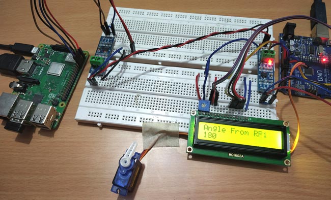
In this tutorial the angle of the servo motor connected with Arduino UNO is controlled by sending angle values from Raspberry Pi to Arduino UNO through RS-485 Serial communication. Raspberry Pi is used as Master and the Arduino UNO with servo motor is used as slave. Also it has a LCD 16x2 display to show the angle value that is received from Raspberry Pi.
Components Required
- Raspberry Pi 3 B+ (With Raspbian OS installed)
- Arduino UNO
- MAX485 TTL to RS485 Converter Module (2)
- SG-90 Servo Motor
- 16x2 LCD
- 10K Potentiometer
- Bread Board
- Connecting Wires
Pin-Out & Features of MAX-485 TTL to RS-485 converter module
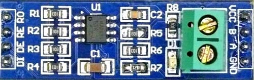
| Pin Name | Pin Description |
| VCC | 5V |
| A | Non-inverting Receiver Input Non-Inverting Driver Output |
| B | Inverting Receiver Input Inverting Driver Output |
| GND | GND (0V) |
| R0 | Receiver Out (RX pin) |
| RE | Receiver Output (LOW-Enable) |
| DE | Driver Output (HIGH-Enable) |
| DI | Driver Input (TX pin) |
MAX-485 TTL to RS-485 converter module has following features:
- Operating voltage: 5V
- On-board MAX485 chip
- A low power consumption for the RS485 communication
- Slew-rate limited transceiver
- 5.08mm pitch 2P terminal
- Convenient RS-485 communication wiring
- Board size: 44 x 14mm
- It allows serial communication over long distance of 1200 meters
Connecting RS-485 Module with Raspberry Pi 3 B+
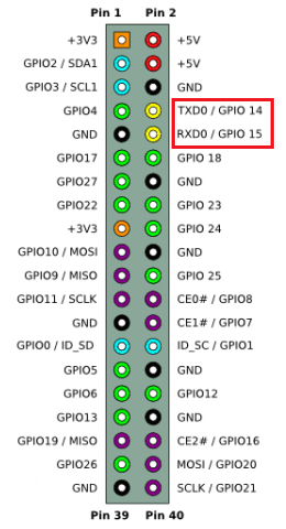
To connect the MAX485 TTL to RS-485 Converted Module to Raspberry Pi the following UART pins of Pi is used (GPIO14, GPIO15).
Connecting RS-485 Module with Arduino UNO
To connect the MAX485 TTL to RS-485 Converter Module to Arduino UNO the following UART pins of UNO is used (0,1).

Circuit Connection between one RS-485 and Raspberry Pi 3 B+ (Master):
|
RS-485 |
Raspberry Pi 3 B+ |
|
DI |
GPIO14 (TX) |
|
DE RE |
GPIO4 |
|
R0 |
GPIO15(RX) |
|
VCC |
5V |
|
GND |
GND |
|
A |
To A of Slave RS-485 |
|
B |
To B of Slave RS-485 |
Circuit Connection between one RS-485 and Arduino UNO (Slave):
|
RS-485 |
Arduino UNO |
|
DI |
1 (TX) |
|
DE RE |
2 |
|
R0 |
0 (RX) |
|
VCC |
5V |
|
GND |
GND |
|
A |
To A of Master RS-485 |
|
B |
To B of Master RS-485 |
Arduino UNO with Servo Motor SG-90:
|
Servo Motor (SG-90) |
Arduino UNO |
|
RED |
+5V |
|
ORANGE (PWM) |
3 |
|
BROWN |
GND |
Circuit Connection between a 16x2 LCD and Arduino UNO:
|
16x2 LCD |
Arduino UNO |
|
VSS |
GND |
|
VDD |
+5V |
|
V0 |
To potentiometer centre pin for contrast control of LCD |
|
RS |
8 |
|
RW |
GND |
|
E |
9 |
|
D4 |
10 |
|
D5 |
11 |
|
D6 |
12 |
|
D7 |
13 |
|
A |
+5V |
|
K |
GND |
This finishes all the necessary circuit connections between all components. Now start programming the Raspberry Pi and Arduino UNO with the Master and Slave code.
Programming Raspberry Pi as Master using Python
In the Master Raspberry Pi, the angle value of range (0,10,45,90,135,180,135,90,45,10,0) is sent to the RS-485 module via serial port of Pi that sends value to the Arduino UNO and controls the servo motor according to that. So, for using Serial port in Raspberry Pi the UART Serial port must be enabled.
Enabling the UART (Serial Port) pins in Raspberry Pi: only bold
Before using UART pins in Raspberry Pi, it needs to be enabled. Follow the steps below to enable the UART (Serial) Pins in Raspberry Pi board.
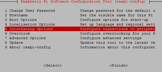
1. Open a terminal and type sudo raspi-config
2. Select Interfacing options
3. And then select serial
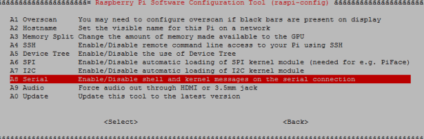
4. Then click on ‘No’ (This is used to disable Linux UART console)
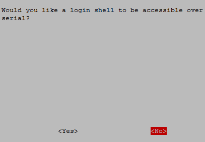
5. After that exit the raspi-config
6. Reboot the Pi
Now Serial port is ready to be used.
IMPORTANT: Before writing values to the RS-485 module the pins DE & RE must be made HIGH.
So, let’s see in detail about Python coding at master side now.
Initially, all the libraries are imported for peripherals used. The libraries which are important here are time, serial(for serial communication), GPIO for accessing GPIO and sleep.
import time
import serial
import RPi.GPIO as GPIO
from time import sleep
Below, GPIO.BOARD option specifies that you are referring to the pins by the number of pin in the board.
GPIO.setmode(GPIO.BOARD)
The GPIO pin number 7 on the Raspberry Pi is made HIGH because the pin 7 of Pi is connected to DE & RE of RS-485.It is made HIGH because it makes RPi to send values to RS-485.
GPIO.setup(7, GPIO.OUT, initial=GPIO.HIGH)
Initiate the serial class at the pins GPIO14 & GPIO 15 (Serial0 Port) with various information like which serial port, baud rate, parity and stop bits.
send = serial.Serial(
    port='/dev/serial0',
    baudrate = 9600,
    parity=serial.PARITY_NONE,
    stopbits=serial.STOPBITS_ONE,
    bytesize=serial.EIGHTBITS,
    timeout=1
)
The variable ‘i’ with array of angle values is defined, these values will be sent via serial communication.
i = [0,10,45,90,135,180,135,90,45,10,0]
The function send.write(str(x)) sends the values to serial port to the RS-485 one by one written inside the while loop as it executes continuously. The values are sent with a delay of 1.5 seconds.
while True:
 for x in i:
     send.write(str(x))
     print(x)
     time.sleep(1.5)
This finishes the code for Raspberry Pi which is acting as master in RS485 based serial communication.
Programming Arduino UNO (Slave)
At the Slave side which is Arduino UNO, the values are received from the Master. The servo motor connected to Arduino is rotated according to the value received, and also the value is displayed in LCD display. So, in Arduino programming LCD display library and Servo motor library used.
IMPORTANT
As the Slave RS-485 of Arduino UNO receives value, the pins DE & RE must be made LOW.
Arduino IDE is used for programming Arduino UNO.
Just like for master we had several peripherals and included necessary libraries, similarly the slave side has peripherals such as servo motor and 16X2 LCD display, so start with including libraries for these peripherals.
#include <LiquidCrystal.h>
#include <Servo.h>
Next the 16X2 LCD display pins that are to be used with the Arduino UNO are defined and then the Servo object is also created.
LiquidCrystal lcd(8,9,10,11,12,13);     // Define LCD display pins RS,E,D4,D5,D6,D7
Servo servo;
Initially a display message is displayed which can be changed according to the project and then it is cleared for next message.
  lcd.begin(16,2);
  lcd.print("CIRCUIT DIGEST");
  lcd.setCursor(0,1);
  lcd.print("RS_485");
  delay(3000);
  lcd.clear();
The serial communication is started at baud rate of 9600.
Serial.begin(9600);
As Arduino RS-485 receives value from master, so the pin 2 of (EnablePin) is made LOW to make it in input mode and also to make pin DE & RE of RS-485 LOW to read value from Master Raspberry Pi.
digitalWrite(enablePin, LOW);
The Servo Motor PWM pin is connected to the Arduino PWM pin 3.
servo.attach(3);
The while loop executes when there is a value available at serial port where RS485 module is connected.
The Serial.paseInt() function is used to receive the integer value (Angle) from serial port that is sent from Raspberry Pi
int angle = Serial.parseInt();
Write the received angle value to servo motor to rotate the servo motor shaft from (0 to 180).
servo.write(angle);
And finally, the angle value is displayed in LCD display using the respective LCD functions.
        lcd.setCursor(0,0);
        lcd.print("Angle From RPi ");
        lcd.setCursor(0,1);
        lcd.print(angle);
This finishes the slave side programming. Also with uploading the codes in Raspberry Pi ad Arduino UNO, both the controllers are ready for a working demo. Complete code with a Demo Video is given at the end of this tutorial.
Testing the RS 485 Serial communication with Raspberry Pi and Arduino UNO
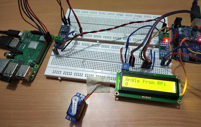
When circuit connections are complete and code is uploaded to Arduino UNO, then use terminal to run the python code in Raspberry Pi. The Angle value is sent from Raspberry Pi to Arduino Uno to control the Servo Motor angle via RS-485 Serial Communication.
1. At Angle: 0
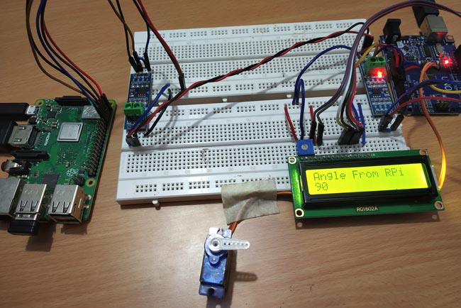
2. At Angle: 90
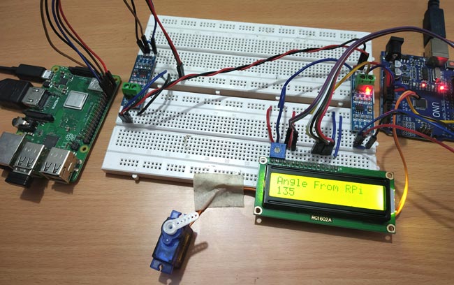
3. At Angle:135
4. At Angle:180
This finishes the complete tutorial on RS485 serial communication using Raspberry Pi. If you have any doubt or suggestions then please comment below.
Complete Project Code
Master Raspberry Pi Code:
import time

import serial

import RPi.GPIO as GPIO

from time import sleep
GPIO.setwarnings(False)

GPIO.setmode(GPIO.BOARD)

GPIO.setup(7, GPIO.OUT, initial=GPIO.HIGH)

send = serial.Serial(

    port='/dev/serial0',

    baudrate = 9600,

    parity=serial.PARITY_NONE,

    stopbits=serial.STOPBITS_ONE,

    bytesize=serial.EIGHTBITS,

    timeout=1

)
i = [0,10,45,90,135,180,135,90,45,10,0]
while True:

 for x in i:

     send.write(str(x))

     print(x)

     time.sleep(1.5)

Slave Arduino Code:
#include <LiquidCrystal.h>              //Include LCD library for using LCD display functions

#include <Servo.h>                //For using Servo functions

int enablePin = 2;
LiquidCrystal lcd(8,9,10,11,12,13);      // Define LCD display pins RS,E,D4,D5,D6,D7
Servo servo;
void setup()

{

  lcd.begin(16,2);

  lcd.print("CIRCUIT DIGEST");

  lcd.setCursor(0,1);

  lcd.print("RS_485");

  delay(3000);

  lcd.clear();

  Serial.begin(9600);                   // initialize serial at baudrate 9600:

  pinMode(enablePin, OUTPUT);

  delay(10);

  digitalWrite(enablePin, LOW);        //  (Pin 2 always LOW to receive value from Master)

  servo.attach(3);                     //  (Servo PWM pin connected to Pin 3 PWM pin of Arduino)

}
void loop()
{

  while (Serial.available())                   //While have data at Serial port this loop executes

     {


        lcd.clear();

        int angle = Serial.parseInt();            //Receive INTEGER value from Master throught RS-485

        servo.write(angle);                       //Write received value to Servo PWM pin (Setting Angle)

        lcd.setCursor(0,0);

        lcd.print("Angle From RPi ");

        lcd.setCursor(0,1);

        lcd.print(angle);                        //Displays the Angle value


    }

 }

I would caution using 5v ttl to drive the Pi 3.3v rx GPIO input. you could release the magic smoke.
at a minimum a voltage divider 2.2k-3.3K (3/5th) to drop the 5v ttl from the rs485 device to the input rx of the pi.