

Analog to Digital converter (ADC) is the most used hardware feature on a microcontroller. It takes in analog voltage and converts it to a digital value. Since microcontrollers are digital devices and work with the binary digit 1 and 0, it could not process the analog data directly. Thus, an ADC is used to take in analog voltage and convert it into its equivalent digital value that a microcontroller can understand. If you want more about Analog to Digital Converter (ADC), you can check the article linked.
There are different sensors available in electronics that provide Analog output, like the MQ gas sensors, ADXL335 Accelerometer sensor, etc. Thus, using Analog to Digital converter, those sensors can be interfaced with a microcontroller unit. You can also check out other tutorials listed below, for using ADC with other microcontrollers.
- How to Use ADC in Arduino Uno?
- Interfacing ADC0808 with 8051 Microcontroller
- Using ADC Module of PIC Microcontroller
- Raspberry Pi ADC Tutorial
- How to use ADC in MSP430G2 - Measuring Analog Voltage
- How to use ADC in STM32F103C8
In this tutorial, we will use the inbuilt ADC peripheral of the N76E003 microcontroller unit so let's evaluate what kind of hardware setup we require for this application.
Components Required and Hardware Setup
To use ADC on N76E003, we will use a voltage divider using a potentiometer and read the voltage ranging from 0V-5.0V. The Voltage will be displayed in the 16x2 Character LCD, if you are new with LCD and N76E003, you can check how to interface LCD with Nuvoton N76E003. Thus, the major component that is required for this project is 16x2 Character LCD. For this project, we will use the below components-
- Character LCD 16x2
- 1k resistor
- 50k potentiometer or trim pot
- Few Berg wires
- Few hookup wires
- Breadboard
Not to mention, other than the above components, we need the N76E003 microcontroller-based development board as well as the Nu-Link Programmer. An additional 5V power supply unit is also required as the LCD draws sufficient current that the programmer could not provide.
Nuvoton N76E003 Circuit Diagram to Read Analog Voltage

As we can see in the schematic, the port P0 is used for the LCD related connection. On the extreme left, the programming interface connection is shown. The potentiometer acts as a voltage divider and that is sensed by the analog input 0 (AN0).
Information about GPIO and Analog Pins in N76E003
The below image is illustrating the GPIO pins available on the N76E003AT20 microcontroller unit. However, out of the 20 pins, For the LCD related connection, the Port P0 (P0.0, P0.1, P0.2, P0.4, P0.5, P0.6, and P0.7) is used. The Analog pins are highlighted in RED colors.
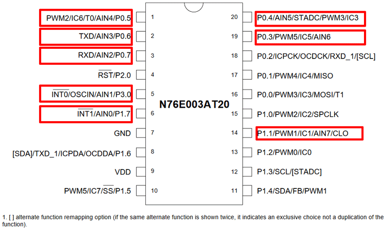
As we can see, the Port P0 has maximum analog pins but those are used for LCD related communication. Thus, P3.0 and P1.7 are available as Analog input pins AIN1 and AIN0. As this project requires only one analog pin, P1.7 which is Analog input channel 0, is used for this project.
Information about ADC Peripheral in N76E003
N76E003 provides a 12-bit SAR ADC. It is a very good feature of the N76E003 that it has a very good resolution of ADC. The ADC has 8-Channel inputs in single-end mode. Interfacing the ADC is pretty simple and straightforward.
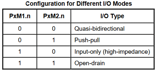
The first step is to select the ADC channel input. There are 8-Channel inputs available in N76E003 microcontrollers. After selecting the ADC inputs or the I/O pins, all the pins are required to be set for the direction in the code. All the pins used for the Analog input are input pins of the microcontroller thus all the pins need to be set as Input-only (high-impedance) mode. These can be set using the PxM1 and PxM2 register. These two registers set the I/O modes where the x stands for the Port number (For example, Port P1.0 the register will be P1M1 and P1M2, for P3.0 it will be P3M1 and P3M2, etc.) The configuration can be seen in the below image-
The configuration of the ADC is done by two registers ADCCON0 and ADCCON1. The ADCCON0 Register description is shown below.
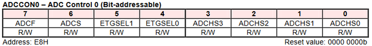
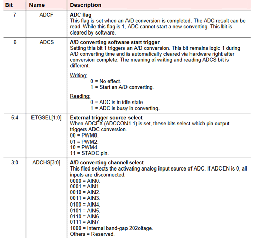
The first 4 bits of the register from bit 0 to bit 3 is used to set the ADC Channel selection. Since we are using the channel AIN0, the selection will be 0000 for these four bits.
The 6th and 7th bits are the important ones. ADCS is required to set 1 for starting the ADC conversion and the ADCF will provide information about the successful ADC conversion. It needs to be set 0 by the firmware for starting the ADC conversion. The next register is the ADCCON1-
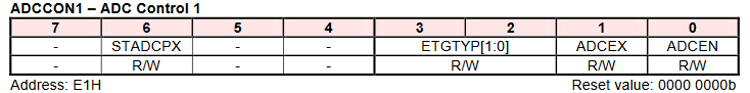
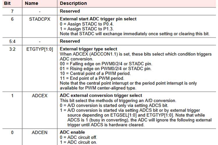
The ADCCON1 register is mainly used for the ADC conversion triggered by external sources. However, for normal polling related operations, the first-bit ADCEN is required to set 1 for turning on the ADC circuitry.
Next, the input of the ADC channel needs to be controlled in the AINDIDS register where the digital inputs can be disconnected.
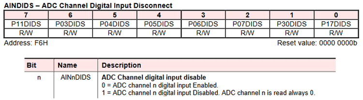
The n stands for the channel bit (For example, the AIN0 channel will need to be controlled using the first bit P17DIDS of AINDIDS register). The digital input needs to be enabled, otherwise, it will read as 0. These all are the basic setting of the ADC. Now, Clearing the ADCF and setting the ADCS the ADC conversion can be started. The converted value will be available in the below registers-
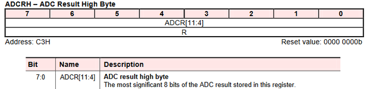
And
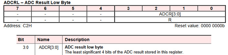
Both registers are 8-bits. As the ADC provides 12-bits data, the ADCRH is used as full (8-bits) and the ADCRL is used as half (4-bits).
Programming N76E003 for ADC
Coding for a specific module every time is a hectic job, thus a simple yet powerful LCD library is provided that will be very useful for 16x2 character LCD interfacing with N76E003. The 16x2 LCD library is available in our Github repository, which can be downloaded from the below link.
Download 16x2 LCD Library for Nuvoton N76E003
Kindly have the library (by cloning or downloading) and just include the lcd.c and LCD.h files in your Keil N76E003 project for easy integration of the 16x2 LCD in the desired application or project. The library will provide the following useful display-related functions-
- Initialize the LCD.
- Send command to the LCD.
- Write to the LCD.
- Put a string in the LCD (16 Characters).
- Print character by sending hex value.
- Scroll long messages with more than 16 characters.
- Print integer numbers directly into the LCD.
The coding for ADC is simple. In the setup function Enable_ADC_AIN0; is used for setting up the ADC for AIN0 input. This is defined in the file.
#define Enable_ADC_AIN0 ADCCON0&=0xF0;P17_Input_Mode;AINDIDS=0x00;AINDIDS|=SET_BIT0;ADCCON1|=SET_BIT0 //P17
So, the above line sets the pin as an input and configures the ADCCON0, ADCCON1 register as well as the AINDIDS register also. The below function will read the ADC from the ADCRH and ADCRL register but with 12-bit resolution.
unsigned int ADC_read(void){
  register unsigned int adc_value = 0x0000;
  clr_ADCF;
  set_ADCS;
  while(ADCF == 0);
  adc_value = ADCRH;
  adc_value <<= 4;
  adc_value |= ADCRL;
  return adc_value;
}
The bit is left-shifted 4 times and then added to the data variable. In the main function, the ADC is reading the Data and getting printed directly on the display. However, the voltage is also converted using a ratio or the relationship between voltage divided by the bit value.
A 12-bit ADC will provide 4095 bit on 5.0V input. Thus dividing the 5.0V/4095 = 0.0012210012210012V
So, 1 digit of bit changes will be equal to the changes in 0.001V (Approximately). This is done in the main function shown below.
void main(void){
             int adc_data;
             setup();
             lcd_com (0x01);
             while(1){
             lcd_com (0x01);
             lcd_com (0x80);
             lcd_puts("ADC Data: ");
             adc_data = ADC_read();
             lcd_print_number(adc_data);
             voltage = adc_data * bit_to_voltage_ratio;
             sprintf( str_voltage, "Volt: %0.2fV", voltage);
             lcd_com(0xC0);
             lcd_puts(str_voltage);
             Timer0_Delay1ms(500);
    }
  }
The data is converted from bit value to voltage and using a sprintf function, the output is converted to a string and sent to the LCD.
Flashing the code and the output
The code returned 0 warning and 0 Errors and was flashed using the default flashing method by the Keil, you can see the flashing message below. If you are new to Keil or Nuvoton, check out the getting started with Nuvoton microcontroller to understand the basics and how to upload the code.
The rebuild started: Project: timer
Rebuild target 'Target 1'
assembling STARTUP.A51...
compiling main.c...
compiling lcd.c...
compiling Delay.c...
linking...
Program Size: data=101.3 xdata=0 code=4162
creating hex file from ".\Objects\timer"...
".\Objects\timer" - 0 Error(s), 0 Warning(s).
Build Time Elapsed:  00:00:02
Load "G:\\n76E003\\Display\\Objects\\timer"
Flash Erase Done.
Flash Write Done: 4162 bytes programmed.
Flash Verify Done: 4162 bytes verified.
Flash Load finished at 11:56:04
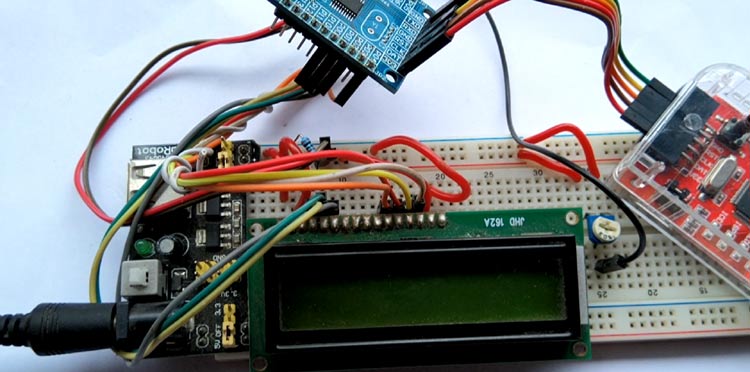
The image below shows the hardware connected in the power source using a DC adapter and the display is showing the voltage output set by the potentiometer on the right.
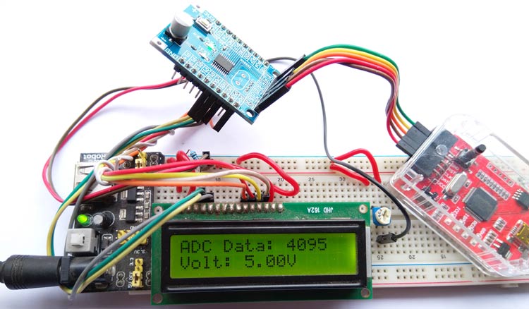
If we turn the potentiometer, the voltage given to the ADC pin will also change and we can notice the ADC value and Analog voltage displayed on the LCD. You can check out the video below for the complete working demonstration of this tutorial.
Hope you enjoyed the article and learned something useful, if you have questions, leave them in the comment section below, or you can use our forums to post other technical questions.
Complete Project Code
#include "N76E003.h"
#include "SFR_Macro.h"
#include "Function_define.h"
#include "Common.h"
#include "Delay.h"
#include "lcd.h"
#define bit_to_voltage_ratio 0.001220703125 // 5.0V divided by 4096 For 12-Bit ADC
void setup (void);
unsigned int ADC_read(void);
float voltage;
char str_voltage[20];
void main(void){
             int adc_data;
             setup();
             lcd_com (0x01);
             while(1){
             lcd_com (0x01);
             lcd_com (0x80);
             lcd_puts("ADC Data: ");
             adc_data = ADC_read();
             lcd_print_number(adc_data);
             voltage = adc_data * bit_to_voltage_ratio;
             sprintf( str_voltage, "Volt: %0.2fV", voltage);
             lcd_com(0xC0);
             lcd_puts(str_voltage);
             Timer0_Delay1ms(500);
    }
  }
void setup (void){
    Set_All_GPIO_Quasi_Mode;
    lcd_init();
    Enable_ADC_AIN0;
    lcd_com (0x80);
    LCD_ScrollMessage("Welcome to CircuitDigest.com");
    lcd_com (0x80);
    lcd_puts("ADC interfacing");
    lcd_com (0xC0);
    lcd_puts ("With N76E003 mcu");
    Timer3_Delay100ms(5);
}
unsigned int ADC_read(void){
  register unsigned int adc_value = 0x0000;
  clr_ADCF;
  set_ADCS;
  while(ADCF == 0);
  adc_value = ADCRH;
  adc_value <<= 4;
  adc_value |= ADCRL;
  return adc_value;
}