 Vedhathiri
Author

In recent years, the demand for smart security and automated monitoring systems has increased significantly due to growing safety concerns and the need for real-time surveillance. Traditional security systems often require continuous human supervision, which can be inefficient and time-consuming. With the advancement of embedded systems and Internet of Things (IoT) technology, it has become possible to design intelligent monitoring solutions that operate automatically and respond instantly to environmental changes for monitoring. No continuous video stream, no local NVR, no subscription, just an instant, evidence-grade ESP32-CAM send picture email notification powered by the free CircuitDigest Cloud API.
This project demonstrates an ESP32 CAM motion detection with a PIR system designed for smart surveillance applications. The setup works as a compact ESP32 CAM motion alert security camera that detects movement, captures images instantly, and notifies the user by sending the captured image to a registered email address through the CircuitDigest Cloud platform. The result is a compact, WiFi-connected ESP32-CAM email alert system that can be deployed in a home entryway, server room, warehouse, or outdoor enclosure. To configure email registration and cloud integration, refer to the guide “How to Send Email Using ESP32” before proceeding with this project.
How to Use the ESP32 CAM Email Alert System for Motion Detection
- Connect the PIR sensor OUT to GPIO13, the red LED to GPIO14 via 220Ω, flash LED to GPIO4.
- Configure the camera with PIXFORMAT_JPEG, FRAMESIZE_VGA, and call esp_camera_init().
- In the loop, read GPIO13 — on HIGH, call captureAndSendImage().
- Capture JPEG to frame buffer with esp_camera_fb_get().
- Send a multipart HTTPS POST to circuitdigest.cloud/api/v1/email/send-with-image with your API key and image buffer.
- Use a MOTION_COOLDOWN timer to prevent repeat triggers — one ESP32-CAM picture email per event.
Table of Contents
Components Required for the ESP32-CAM Email Alert System
The table below lists every component needed to build this ESP32-CAM motion detection email alert system.
| S.No | Components | Purpose |
| 1. | ESP32-Cam | Acts as the main controller and is used to capture images |
| 2. | PIR Sensor | Used to detect the motion. |
| 3. | Breadboard | To ease the Connection between the components by integrating in a compact way |
| 4. | Jumper Wires | To make the connections between the components |
| 5. | Red LED | For the process indication |
| 6. | 220 Ohms Resistor | To protect the LED |
Important: If you are using the standard ESP32-CAM (without onboard USB), you will need a USB-to-Serial (FTDI) adapter for programming. Connect FTDI TX → ESP32-CAM RX (U0R), RX → TX (U0T), GND → GND, and hold GPIO0 LOW during upload to enter flash mode. If your board has a micro-USB port already, no adapter is required. If you are just getting started with the ESP32-CAM module, we recommend checking out our guide “How to Program the ESP32-CAM?
Circuit Diagram of ESP32-CAM with PIR Sensor for Motion Detection Email Alert
The circuit diagram shows the direct interfacing of a PIR motion sensor with the ESP32-CAM module to enable motion detection. The wiring for this ESP32-CAM motion detection email alert system uses only three signal connections: The VCC and GND pins connected as required, and the output (data) pin of the PIR sensor is connected to GPIO13 of the ESP32-CAM, which is configured as a digital input to detect motion signals.

In addition, a red LED is connected to the ESP32-CAM to serve as a backend status indicator. The LED can be programmed to display different system states such as Wi-Fi connection status, active monitoring mode, or motion detection events.
ESP32-CAM Pin Connection Table
| Component Pin | ESP32-CAM GPIO | Direction / Note |
| PIR VCC | 5V | Power — HC-SR501 requires 5V |
| PIR OUT (signal) | GPIO13 | Digital INPUT — HIGH on motion |
| PIR GND | GND | Common ground |
| Red LED anode | GPIO14 → 220Ω → LED → GND | Digital OUTPUT — status indicator |
| Flash LED | GPIO4 (onboard) | Digital OUTPUT — fires during image capture |
GPIO Note: On the ESP32-CAM AI Thinker, GPIO pins 0, 2, 4, 12, 13, 14, 15, and 16 are shared or used by the camera interface. GPIOs 13 and 14 are safe for PIR and LED, respectively. Avoid using GPIO0 (boot mode) and the camera data pins (32–39) for external signals.
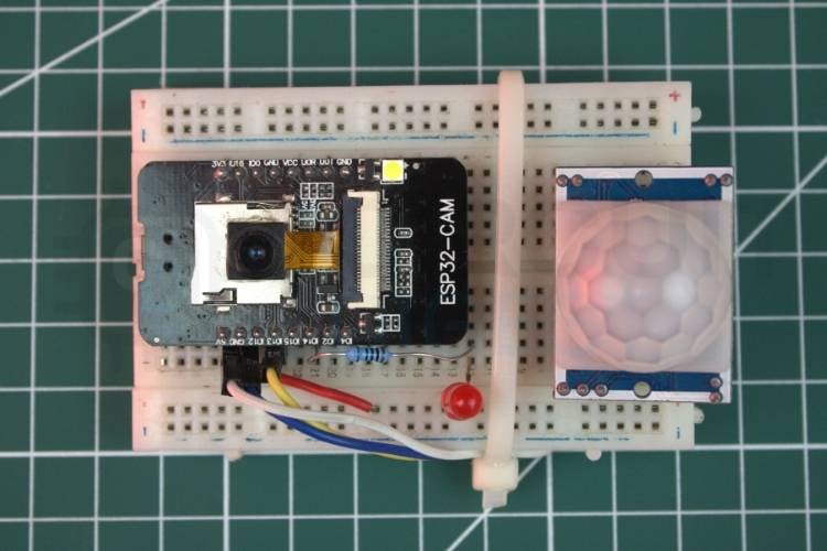
Hardware Configuration of the ESP32-CAM Send Email Alert
The hardware setup explains what are all the real-time components used in this project and how they are interconnected to ensure proper functionality. It displays the correct wiring between the ESP32-CAM, Red LED, resistor and the PIR sensor to get reliable operation.
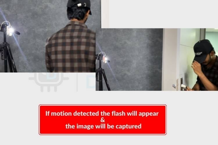
How the ESP32-CAM Detects Motion and Sends Picture Emails
The system operates by integrating an ESP32-CAM module the PIR sensor continuously monitors the surroundings for motion. Once movement is detected, it sends a signal to the ESP32-CAM, which immediately captures a photo and processes it for notification. This integration allows the system to function as an efficient motion-activated camera. The system operates as a fully autonomous ESP32-CAM email notification pipeline.
To indicate the system status, a red LED is connected during system setup. The red LED blinks continuously to show initialization. Once the setup is complete, the LED blinks once every second to indicate that the system is actively monitoring for motion. When motion is detected, the red LED stops blinking, and the onboard flash LED turns on immediately, indicating that an image is being captured. After capturing the image, the ESP32-CAM temporarily stores it in memory. The module then connects to the configured Wi-Fi network and prepares an API request containing the required payload details. The image data is attached to this request and sent securely to the Circuit Digest Cloud server.
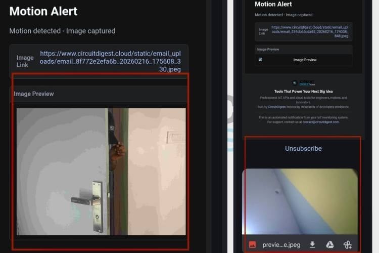
Before transmission, the system ensures that the payload structure is properly formatted according to API requirements. Once the server receives and verifies the request, it processes the image and triggers an email notification to the registered email address. The email contains the captured image as an attachment, allowing the user to view or download it within a few seconds of motion detection. If you’re looking for more exciting ESP32-CAM projects, check out this Automatic License Plate Recognition tutorial on CircuitDigest.
Code Explanation for the ESP32-CAM Motion Detection Email Alert System
The sketch for this ESP32-CAM email notification using cloud API project code is structured into setup, loop, image capture, and email transmission sections. In the setup function, WiFi, camera configuration, GPIO pins, and sensor initialization are performed. The loop function continuously reads the PIR sensor and manages timing control using millis() to prevent repeated triggers. When motion is confirmed, a separate function handles image capture using the camera frame buffer. Another dedicated function constructs and sends an HTTPS POST request with multipart form data to deliver the captured image via email.
const char* ssid = "yourssidname";
const char* password = "yourpassword";
const char* host = "www.circuitdigest.cloud";
const int httpsPort = 443;
const char* apiKey = "yourapikey";
This section defines the network credentials and server details required for sending the email. The ESP32-CAM connects to WiFi using the SSID and password. The host address, HTTPS port (443), and API key are necessary to authenticate and securely communicate with the email server.
#define PIR_PIN 13
#define RED_LED_PIN 14
#define FLASH_LED_PIN 4
Here, the GPIO pins for the PIR sensor and LEDs are defined. The PIR sensor detects motion and sends a HIGH signal to the ESP32. The red LED indicates system status, and the flash LED turns ON during image capture to signal that a photo is being taken.
camera_config_t config;
config.pixel_format = PIXFORMAT_JPEG;
config.frame_size = FRAMESIZE_VGA;
config.jpeg_quality = 12;
if (esp_camera_init(&config) != ESP_OK) {
 Serial.println("Camera Init Failed!");
 while (1);
}
This part configures the camera settings, such as image format and resolution. The ESP32-CAM initializes the camera before starting motion monitoring. If initialization fails, the system stops execution to prevent further errors.
int pirState = digitalRead(PIR_PIN);
if (pirState == HIGH) {
   if (currentTime - lastMotionTime > MOTION_COOLDOWN) {
       lastMotionTime = currentTime;
       captureAndSendImage();
   }
}
In the loop function, the ESP32 continuously reads the PIR sensor. When motion is detected, it checks the cooldown timer to avoid repeated triggers. If the condition is satisfied, it calls the image capture function. This ensures stable and controlled motion-based activation.
camera_fb_t* fb = esp_camera_fb_get();
digitalWrite(FLASH_LED_PIN, HIGH);
When motion is confirmed, the ESP32 activates the flash LED and captures an image using the camera. The captured image is stored temporarily in a frame buffer (fb). After processing, the buffer is released to free memory for future captures.
WiFiClientSecure client;
client.setInsecure();
client.connect(host, httpsPort);
client.println("POST /api/v1/email/send-with-image HTTP/1.1");
client.println("Authorization: Bearer " + String(apiKey));
client.write(fb->buf, fb->len);
In this final stage, the ESP32 creates a secure HTTPS connection using WiFiClientSecure. It prepares a multipart HTTP POST request containing the recipient email, template ID, variables, and the captured image. After sending the request, it waits for the server's response. Once the server verifies the payload and API key, the email with the attached image is delivered to the registered email address.
Real-World Applications of the ESP32-CAM Email Alert System
The combination of passive infrared detection, on-device image capture, and ESP32-CAM email notification using cloud API creates a versatile platform that covers a wide range of surveillance and safety applications, particularly relevant in India's growing smart infrastructure sector.
- Home Security
This system can be used to monitor homes and detect unauthorized movement. When motion is detected, the captured image is sent instantly to the owner’s email for quick action. - Office Surveillance
It can monitor restricted office areas such as cabins or storage rooms. The system provides real-time image alerts whenever motion is detected. After-hours motion in these zones generates an immediate ESP32-CAM send image email to the security team, providing a timestamped visual record that supports both incident response and compliance reporting. - Warehouse Protection
The system helps protect valuable goods in warehouses by capturing and sending images during unexpected movement, especially after working hours. - Remote Area Monitoring
It can be installed in farms, construction sites, or isolated buildings to monitor activity and send alerts from distant locations. - IoT-Based Smart Alert Systems
This project serves as a foundation for advanced IoT security systems and can be integrated with alarms or cloud-based monitoring platforms.
This ESP32 CAM motion detection with photo alert solution can be used for home security, office monitoring, warehouse surveillance, and other IoT-based safety systems where instant visual confirmation is required.
Troubleshooting the ESP32-CAM Motion Detection Email Alert System
The most common failure modes of this ESP32-CAM send email alert project to their root causes are verified solutions, drawing on hands-on testing experience.
- Issue 1: ESP32-CAM Not Connecting to Wi-Fi
Solution:
Ensure the correct SSID and password are entered in the code. Check whether the Wi-Fi network is stable and within range of the ESP32-CAM. Also, verify that the board is receiving sufficient power, as low voltage can interrupt Wi-Fi connectivity. - Issue 2: Camera Initialization Failed
Solution:
Confirm that the correct ESP32-CAM board model (AI Thinker) is selected in the Arduino IDE. Check all camera pin configurations in the code to ensure they match the module specifications. Insufficient power supply can also cause camera initialization failure. - Issue 3: Image Not Captured or Capture Failed
Solution:
Verify that the camera module is properly connected and not physically damaged. Reduce the frame size or increase JPEG compression if memory issues occur. Restart the ESP32-CAM and check for error messages in the Serial Monitor for debugging. - Issue 4: Email Not Sent or API Error
Solution:
Make sure the API key is valid and correctly entered in the code. Check whether the payload format and template ID match the requirements of the Circuit Digest Cloud platform. Also, ensure that the ESP32-CAM has an active internet connection before sending the request. - Issue 5: Frequent False Motion Detection
Solution:
Adjust the PIR sensor sensitivity and delay settings using its onboard potentiometers. Ensure the sensor is not facing heat sources like sunlight or electrical appliances. The cooldown timer in the code can also be increased to reduce repeated triggering.
Conclusion
Overall, this ESP32 CAM email alert system with motion detection capture project provides a cost-effective and efficient security solution. By combining PIR sensing with real-time image capture, it delivers a reliable ESP32 CAM motion alert security camera system suitable for modern smart environments. It combines sensing, image capture, Wi-Fi communication, and cloud integration simply and practically. The setup is easy to understand and focuses on proper hardware connections and structured programming. Overall, it gives a clear idea of how embedded systems and IoT technology can be used to create a basic but effective real-time security solution. If you’re looking for exciting projects related to ESP32, check out these awesome ESP32 builds that showcase the versatility of this powerful microcontroller
Frequently Asked Questions
1. Why does the ESP32-CAM sometimes fail to capture images?
This may happen due to insufficient power supply, incorrect camera configuration, or loose connections. The ESP32-CAM requires a stable 5V supply with adequate current for proper camera operation.
2. Why is my email not being sent?
Email transmission depends on correct Wi-Fi connectivity, proper API endpoint configuration, and correctly formatted payload data. If any parameter (like API key or template ID) is incorrect, the cloud server will reject the request.
3. How far can the PIR sensor detect motion?
Typically, a PIR sensor can detect motion within 5 to 7 meters, depending on the model and environmental conditions. Sensitivity and delay time can usually be adjusted using onboard potentiometers.
4. Can I store images locally instead of sending emails?
Yes. The ESP32-CAM can save captured images to a microSD card. The code needs to include SD card initialization and file storage logic.
5. Is this system suitable for security applications?
Yes, it can be used for basic security monitoring. However, for professional-grade security systems, additional features like encryption, secure authentication, and tamper detection should be implemented.
6. Why does the PIR sensor give false triggers sometimes?
False triggers can occur due to sudden temperature changes, moving heat sources, or electrical noise. Proper placement and a stable power supply can reduce such issues.
ESP32-CAM Email Alert GitHub Repository
The entire sketch is available through this GitHub project, which contains a complete version of the code used to program these functions. The ESP32-CAM email alert repository includes the entire .ino file that includes all camera pins for the AI Thinker ESP32-CAM board, how to set up Wi-Fi, how to cycle through a PIR while checking for motion, how to take a picture with the camera, and how to send email using Multipart HTTPS POST. It is ready to clone, configure with your CircuitDigest Cloud credentials, and upload!


Projects Using Email Feature and ESP32-Cam
If you need more projects related to the Email Feature and ESP32-Cam, check out the links below

Real-Time Image Capture and Email Notification Using ESP32-CAM
ESP32-CAM real-time image capture with email notifications using Wi-Fi and API integration for instant smart surveillance alerts.

Face Mask Detection using ESP32 CAM
ESP32-CAM face mask detection system that captures images, identifies mask usage with AI, and provides real-time safety alerts.

How to Send E-mail using PIC Microcontroller and ESP8266
Send emails using PIC16F877A and ESP8266 by interfacing over UART and using AT commands to trigger email alerts via SMTP on a Wi-Fi network
Complete Project Code
#include "esp_camera.h"
#include <WiFi.h>
#include <WiFiClientSecure.h>
/* ================= WIFI ================= */
const char* ssid = "yourssid";
const char* password = "yourpassword";
/* ================= EMAIL API ================= */
const char* host = "www.circuitdigest.cloud";
const int httpsPort = 443;
const char* apiKey = "yourapikey";
/* ================= PIR SENSOR ================= */
#define PIR_PIN 13
/* ================= LED PINS ================= */
#define RED_LED_PIN 14
#define FLASH_LED_PIN 4
/* ================= ESP32-CAM AI THINKER ================= */
#define PWDN_GPIO_NUM     32
#define RESET_GPIO_NUM    -1
#define XCLK_GPIO_NUM      0
#define SIOD_GPIO_NUM     26
#define SIOC_GPIO_NUM     27
#define Y9_GPIO_NUM       35
#define Y8_GPIO_NUM       34
#define Y7_GPIO_NUM       39
#define Y6_GPIO_NUM       36
#define Y5_GPIO_NUM       21
#define Y4_GPIO_NUM       19
#define Y3_GPIO_NUM       18
#define Y2_GPIO_NUM        5
#define VSYNC_GPIO_NUM    25
#define HREF_GPIO_NUM     23
#define PCLK_GPIO_NUM     22
/* ================= SETTINGS ================= */
const unsigned long MOTION_COOLDOWN = 15000;   // 15 sec
const unsigned long STABLE_TIME = 500;         // 0.5 sec stable detection
const unsigned long LED_BLINK_INTERVAL = 1000;
unsigned long lastMotionTime = 0;
unsigned long lastLedToggle = 0;
bool ledState = false;
/* ================= SETUP ================= */
void setup() {
 Serial.begin(115200);
 Serial.println("\nESP32-CAM Motion System Starting...");
 pinMode(RED_LED_PIN, OUTPUT);
 pinMode(FLASH_LED_PIN, OUTPUT);
 digitalWrite(RED_LED_PIN, LOW);
 digitalWrite(FLASH_LED_PIN, LOW);
 pinMode(PIR_PIN, INPUT);   // IMPORTANT: No pulldown
 Serial.println("Warming up PIR (60 sec)...");
 delay(60000);
 Serial.println("PIR Ready!");
 /* ===== WIFI ===== */
 WiFi.begin(ssid, password);
 Serial.print("Connecting to WiFi");
 while (WiFi.status() != WL_CONNECTED) {
   delay(500);
   Serial.print(".");
 }
 Serial.println("\nWiFi Connected!");
 /* ===== CAMERA CONFIG ===== */
 camera_config_t config;
 config.ledc_channel = LEDC_CHANNEL_0;
 config.ledc_timer   = LEDC_TIMER_0;
 config.pin_d0 = Y2_GPIO_NUM;
 config.pin_d1 = Y3_GPIO_NUM;
 config.pin_d2 = Y4_GPIO_NUM;
 config.pin_d3 = Y5_GPIO_NUM;
 config.pin_d4 = Y6_GPIO_NUM;
 config.pin_d5 = Y7_GPIO_NUM;
 config.pin_d6 = Y8_GPIO_NUM;
 config.pin_d7 = Y9_GPIO_NUM;
 config.pin_xclk = XCLK_GPIO_NUM;
 config.pin_pclk = PCLK_GPIO_NUM;
 config.pin_vsync = VSYNC_GPIO_NUM;
 config.pin_href = HREF_GPIO_NUM;
 config.pin_sscb_sda = SIOD_GPIO_NUM;
 config.pin_sscb_scl = SIOC_GPIO_NUM;
 config.pin_pwdn = PWDN_GPIO_NUM;
 config.pin_reset = RESET_GPIO_NUM;
 config.xclk_freq_hz = 20000000;
 config.pixel_format = PIXFORMAT_JPEG;
 config.frame_size = FRAMESIZE_VGA;
 config.jpeg_quality = 12;
 config.fb_count = 1;
 if (esp_camera_init(&config) != ESP_OK) {
   Serial.println("Camera Init Failed!");
   while (1);
 }
 Serial.println("System Ready - Monitoring...");
}
/* ================= LOOP ================= */
void loop() {
 unsigned long currentTime = millis();
 static unsigned long pirHighStart = 0;
 static bool pirWasHigh = false;
 int pirState = digitalRead(PIR_PIN);
 // DEBUG: show PIR state
 Serial.println(pirState);
 if (pirState == HIGH) {
   if (!pirWasHigh) {
     pirHighStart = currentTime;
     pirWasHigh = true;
   }
   if (currentTime - pirHighStart >= STABLE_TIME) {
     if (currentTime - lastMotionTime > MOTION_COOLDOWN) {
       lastMotionTime = currentTime;
       captureAndSendImage();
     }
   }
 } else {
   pirWasHigh = false;
 }
 /* ===== LED STATUS ===== */
 if (currentTime - lastMotionTime > MOTION_COOLDOWN) {
   if (currentTime - lastLedToggle > LED_BLINK_INTERVAL) {
     ledState = !ledState;
     digitalWrite(RED_LED_PIN, ledState);
     lastLedToggle = currentTime;
   }
 } else {
   digitalWrite(RED_LED_PIN, HIGH);
 }
 delay(200);
}
/* ================= CAPTURE ================= */
void captureAndSendImage() {
 Serial.println("Motion Confirmed - Capturing Image");
 digitalWrite(FLASH_LED_PIN, HIGH);
 delay(150);
 camera_fb_t* fb = esp_camera_fb_get();
 digitalWrite(FLASH_LED_PIN, LOW);
 if (!fb) {
   Serial.println("Capture Failed!");
   return;
 }
 sendEmailWithImage(fb);
 esp_camera_fb_return(fb);
 Serial.println("Capture Done\n");
}
/* ================= EMAIL ================= */
bool sendEmailWithImage(camera_fb_t* fb) {
 WiFiClientSecure client;
 client.setInsecure();
 Serial.println("Connecting to server...");
 if (!client.connect(host, httpsPort)) {
   Serial.println(" Server Connection Failed!");
   return false;
 }
 Serial.println("Connected to server");
 String boundary = "----ESP32CAMBoundary";
 String bodyStart =
   "--" + boundary + "\r\n"
   "Content-Disposition: form-data; name=\"to_email\"\r\n\r\n"
   "[email protected]\r\n"
   "--" + boundary + "\r\n"
   "Content-Disposition: form-data; name=\"template_id\"\r\n\r\n"
   "1002\r\n"
   "--" + boundary + "\r\n"
   "Content-Disposition: form-data; name=\"variables\"\r\n\r\n"
   "{\"title\":\"Motion Alert\",\"description\":\"Motion detected - Image captured\"}\r\n"
   "--" + boundary + "\r\n"
   "Content-Disposition: form-data; name=\"image\"; filename=\"motion.jpg\"\r\n"
   "Content-Type: image/jpeg\r\n\r\n";
 String bodyEnd = "\r\n--" + boundary + "--\r\n";
 int contentLength = bodyStart.length() + fb->len + bodyEnd.length();
 client.println("POST /api/v1/email/send-with-image HTTP/1.1");
 client.println("Host: " + String(host));
 client.println("Authorization: Bearer " + String(apiKey));
 client.println("Content-Type: multipart/form-data; boundary=" + boundary);
 client.print("Content-Length: ");
 client.println(contentLength);
 client.println();
 client.print(bodyStart);
 client.write(fb->buf, fb->len);
 client.print(bodyEnd);
 Serial.println("Request sent. Waiting for response...");
 //  Read server response
 unsigned long timeout = millis();
 while (client.available() == 0) {
   if (millis() - timeout > 5000) {
     Serial.println(" Server Timeout!");
     client.stop();
     return false;
   }
 }
 // Print response
 while (client.available()) {
   String line = client.readStringUntil('\r');
   Serial.print(line);
 }
 client.stop();
 Serial.println("\nConnection closed");
 return true;
}
