

At CircuitDigest, we love experimenting with the ESP32-CAM projects, and today we're building a license plate recognition system with it. In this tutorial, we'll give you step-by-step instructions with circuit diagram and code to walk you through capturing an image of a car or bike, sending it to a cloud server that uses AI to recognize the license plate, and retrieving the decoded characters back to the ESP32-CAM. By the end, you'll not only have a functioning system but also the skills to create projects like smart parking systems, automatic toll gates, and vehicle validation systems. Let’s get started!
Just like our previous project, the ESP32-CAM QR Code Scanner, we're now going to explore a new API from Circuit Digest. This API simplifies the process of recognizing vehicle number plates. Unlike other OCR projects, you don't need to handle all the machine learning tasks yourself. Instead, you simply capture the image and send it to the server, which handles all the backend processing and returns the result to you. It's that simple.
How does this works?
In a nutshell, we use the ESP32-CAM to capture an image, which is then sent to the Circuit Digest cloud server. The server handles the number plate recognition and sends the result back to the device. Essentially, all the machine learning tasks are managed by the server itself. Since this process relies on an API, it’s not limited to the ESP32-CAM; it can work on any device with a camera and internet access.
Components Required for Number Plate Detection
Here, as we already know, the selection of components is a straightforward process. All the components are affordable and commonly available, so you’re not limited to our specific choices.
- ESP32 CAM x1
- 0.96” OLED Display x1
- Push Button x1
- Resistor 10K x1
- Any USB to UART Converter x1
- Bread Board x1
- Jumper Wires - Required Quantity
Circuit Diagram of License Plate Recognition Using ESP32-CAM
The circuit diagram for the License Plate Recognition project is quite simple and uses only a few components. Below is the diagram illustrating the setup for this project.

In this setup, the USB to UART Module is connected to the ESP32-CAM as follows: VCC to 5V, GND to GND, TX to RX, and RX to TX. The ESP32-CAM lacks built-in I2C support, so GPIO14 (SCL) and GPIO15 (SDA) are utilized to connect the OLED display. These pins are configured as I2C using the Wire library. The OLED display will present the scanning results. GPIO13 serves as a digital input pin for the push button, which initiates the scanning process. A 10k resistor is used to pull GPIO13 down, keeping it in an active low state.

In the image above, you can see the assembled components following the circuit diagram. The ESP32-CAM is suspended with jumper wires, while the other components are mounted on the breadboard. You may notice the use of a micro USB breakout board in place of a USB to UART module. This is because the ESP32 was already programmed, and the image was taken during a live demonstration. For powering the module, the micro USB breakout board was used. For a proper setup, however, a USB to UART converter module should be connected.
Programming ESP32-CAM for Number Plate Recognition
Finally, we came to the coding part of the project. Before diving into the main code, we need an API key to access the server via API. So, let's first see how to generate the API key.
Generating the API Key
Generating the API Key is a simple and straightforward process. To create your own API Key, follow the steps provided in the article Number Plate Recognition API for Low-Power Embedded SoC Boards. This article will guide you through the steps to generate an API Key and also provide more information about the Number Plate Recognition API. Once you receive the API Key, you can proceed to the next steps.
For Easy understanding, this code is divided into three segments to provide the best explanation.
Part 1: Setup and Configuration
This section includes necessary libraries and defines settings for the ESP32-CAM, OLED display, and other components. It sets up WiFi credentials, camera pins, and OLED display parameters.
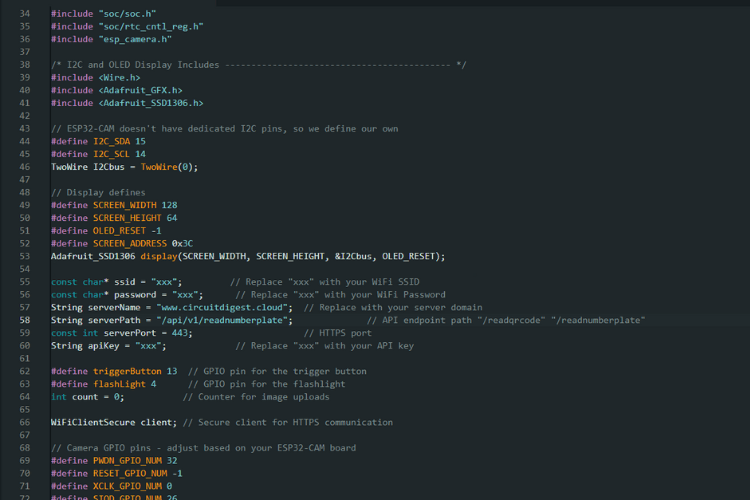
Here, necessary libraries for WiFi, HTTPS, camera, and OLED display functionalities. GPIOs are also declared here for variables such as I2C_SDA, I2C_SCL, triggerButton, and flashLight. Includes placeholders for WiFi credentials (ssid and password), server details (serverName and serverPath), and apiKey. You need to add WiFi credentials and API key. Server details can be kept unchanged.
Part 2: Initialization and Custom Functions
Custom Functions: Functions to extract JSON values and display text on the OLED. There is a function available, which is extractJsonStringValue to extract string values. It is standalone function, but you can still utilize some JSON library to do the same function.

setup() Function: Initializes the serial communication, connects to WiFi, configures the camera, and initializes the OLED display. It also disables the brownout detector and sets up the GPIO pins for the flashlight and trigger button.
Part 3: Main Loop
loop() Function:
Monitors the trigger button. If pressed, it calls the sendPhoto() function to capture and send a photo. It is also responsible for receiving the response from the server and displaying the result on the OLED display.

“sendPhoto()” Function:
sendPhoto Function does 4 different tasks:
- Image Capture: Turns on the flashlight, captures an image, and stores it in the framebuffer.
- Server Connection: Connects to the server using secure HTTPS.
- Image Upload: Prepares and sends the HTTP POST request with the captured image. To exactly understand the format of the data that needs to be sent, kindly look at the API Details.
- Response Handling: Extracts Number Plate Data from the server response and displays it on the OLED. As we know already, we will receive a JSON String from the server as a response.
Thereby, the code explanation is completed. Next, let's upload the code and test its functionality.
Working Demonstration of ESP32 CAM Number Plate Recognition Project
Begin by uploading the provided code to the ESP32-CAM. If you're new to this, check out our detailed guide on programming the ESP32-CAM using the Arduino IDE. Make sure all connections on your breadboard and ESP32-CAM are correct before continuing.
After the code is uploaded, the ESP32-CAM will try to connect to the WiFi network you specified. Double-check that your WiFi credentials in the code are accurate and that your network is active.
Once the ESP32-CAM connects to the WiFi successfully, an initialization message will appear on the OLED display, indicating that the device is ready to capture images. Press the trigger button to start the process. After a brief delay, the result will be displayed on both the OLED screen and the Serial Monitor.
The GIF above demonstrates how the uploaded code operates. Keep in mind that the time it takes for the number plate recognition process to complete depends on your network speed. Reducing the image quality can help speed up the process. It's also crucial to ensure that the camera is properly focused on the number plate. Since Optical Character Recognition (OCR) is performed on the server, every pixel matters. The clearer the number plate, the more accurate the recognition results will be.
Thus we have successfully demonstrated the number plate recognition project.
The License Plate Recognition project using the ESP32-CAM and Circuit Digest’ Cloud API simplifies vehicle number plate detection by offloading machine learning tasks to a cloud server. This setup involves common components like an OLED display and a push button, allowing the ESP32-CAM to capture images which are then processed by the server to identify number plates.
The detailed code and component list make this project both accessible and customizable for DIY enthusiasts. Successful implementation highlights the ease of integrating cloud-based APIs with embedded systems, providing real-time feedback via the OLED display and Serial Monitor. While network speed and image quality can affect recognition accuracy, this project effectively demonstrates the power of combining hardware and cloud services for sophisticated image recognition tasks. Hope you all learned something new. Let’s meet with another new API next time.
GitHub Repository and Source Files
Access the complete source code for this ESP32 CAM for Automatic Number Plate Recognition check out the GitHub Repository


This tutorial was created by the CircuitDigest engineering team. Our experts focus on creating practical, hands-on tutorials to help makers and engineers learn Raspberry Pi projects, Arduino projects, ESP32 projects and more.
Similar Projects

License Plate Recognition using Raspberry Pi and OpenCV Primary tabs View Edit Delete Revisions
It involves capturing images of vehicle license plates and processing them with OpenCV for accurate recognition. The guide covers the setup of the Raspberry Pi, integration with a camera module, and the development of software to handle image processing and plate detection, offering a practical solution for automated vehicle identification.

Car Number Plate Detection Using MATLAB and Image Processing
Explains how to detect vehicle number plates using MATLAB and image processing techniques. It covers the steps to preprocess images, apply detection algorithms, and extract license plate information. The guide provides a detailed approach to implementing the recognition system, leveraging MATLAB’s powerful image processing toolbox for accurate vehicle identification.
 using Tesseract on Raspberry Pi")
Optical Character Recognition (OCR) using Tesseract on Raspberry Pi
Demonstrates how to perform Optical Character Recognition (OCR) using Tesseract on a Raspberry Pi. It details the setup of the Raspberry Pi, installation of Tesseract OCR software, and integration with a camera module to capture and recognize text from images. The guide provides step-by-step instructions for configuring and running Tesseract, showcasing how to implement effective OCR for text extraction on a compact, affordable platform.
Complete Project Code
/*
 * ESP32-CAM Vehicle Number Plate Recognition
 *
 * Overview:
 * This project uses the ESP32-CAM to capture an image of a vehicle's number plate
 * and sends it to the Circuit Digest cloud server for recognition. The server
 * processes the image using machine learning models and returns the recognized
 * number plate data. The result is displayed on an OLED screen connected to the ESP32-CAM.
 *
 * Features:
 * - Captures an image using the ESP32-CAM.
 * - Sends the captured image to a cloud server via a secure HTTPS connection.
 * - Receives and displays the recognized number plate data.
 * - Uses an OLED display to show status messages and results.
 * - Supports any device with a camera and internet access using the API.
 *
 * Components Required:
 * - ESP32-CAM Module
 * - OLED Display (SSD1306)
 * - Push Button (Trigger button)
 * - Flashlight (LED)
 *
 * Note:
 * Ensure that the ESP32-CAM is correctly wired, including the I2C pins for the OLED display.
 */
// This code captures an image using the ESP32-CAM and sends it to a server for processing.
// The captured image is uploaded securely via HTTPS, and the response from the server
// is processed to extract specific information like number plate recognition data.
// Libraries for WiFi, Secure Client, and Camera functionalities
#include <Arduino.h>
#include <WiFi.h>
#include <WiFiClientSecure.h>
#include "soc/soc.h"
#include "soc/rtc_cntl_reg.h"
#include "esp_camera.h"
/* I2C and OLED Display Includes ------------------------------------------- */
#include <Wire.h>
#include <Adafruit_GFX.h>
#include <Adafruit_SSD1306.h>
// ESP32-CAM doesn't have dedicated I2C pins, so we define our own
#define I2C_SDA 15
#define I2C_SCL 14
TwoWire I2Cbus = TwoWire(0);
// Display defines
#define SCREEN_WIDTH 128
#define SCREEN_HEIGHT 64
#define OLED_RESET -1
#define SCREEN_ADDRESS 0x3C
Adafruit_SSD1306 display(SCREEN_WIDTH, SCREEN_HEIGHT, &I2Cbus, OLED_RESET);
const char* ssid = "xxx";         // Replace "xxx" with your WiFi SSID
const char* password = "xxx";      // Replace "xxx" with your WiFi Password
String serverName = "www.circuitdigest.cloud";  // Replace with your server domain
String serverPath = "/api/v1/readnumberplate";              // API endpoint path "/readqrcode" "/readnumberplate"
const int serverPort = 443;                     // HTTPS port
String apiKey = "xxx";             // Replace "xxx" with your API key
#define triggerButton 13  // GPIO pin for the trigger button
#define flashLight 4      // GPIO pin for the flashlight
int count = 0;           // Counter for image uploads
WiFiClientSecure client; // Secure client for HTTPS communication
// Camera GPIO pins - adjust based on your ESP32-CAM board
#define PWDN_GPIO_NUM 32
#define RESET_GPIO_NUM -1
#define XCLK_GPIO_NUM 0
#define SIOD_GPIO_NUM 26
#define SIOC_GPIO_NUM 27
#define Y9_GPIO_NUM 35
#define Y8_GPIO_NUM 34
#define Y7_GPIO_NUM 39
#define Y6_GPIO_NUM 36
#define Y5_GPIO_NUM 21
#define Y4_GPIO_NUM 19
#define Y3_GPIO_NUM 18
#define Y2_GPIO_NUM 5
#define VSYNC_GPIO_NUM 25
#define HREF_GPIO_NUM 23
#define PCLK_GPIO_NUM 22

// Function to extract a JSON string value by key
String extractJsonStringValue(const String& jsonString, const String& key) {
  int keyIndex = jsonString.indexOf(key);
  if (keyIndex == -1) {
    return "";
  }
  int startIndex = jsonString.indexOf(':', keyIndex) + 2;
  int endIndex = jsonString.indexOf('"', startIndex);
  if (startIndex == -1 || endIndex == -1) {
    return "";
  }
  return jsonString.substring(startIndex, endIndex);
}
// Function to display text on OLED
void displayText(String text) {
  display.clearDisplay();
  display.setCursor(0, 10);
  display.setTextSize(1);
  display.setTextColor(SSD1306_WHITE);
  display.print(text);
  display.display();
}
void setup() {
  // Disable brownout detector
  WRITE_PERI_REG(RTC_CNTL_BROWN_OUT_REG, 0);
  Serial.begin(115200);
  pinMode(flashLight, OUTPUT);
  pinMode(triggerButton, INPUT);
  digitalWrite(flashLight, LOW);
  // Connect to WiFi
  WiFi.mode(WIFI_STA);
  Serial.println();
  Serial.print("Connecting to ");
  Serial.println(ssid);
  WiFi.begin(ssid, password);
  while (WiFi.status() != WL_CONNECTED) {
    Serial.print(".");
    delay(500);
  }
  Serial.println();
  Serial.print("ESP32-CAM IP Address: ");
  Serial.println(WiFi.localIP());
  // Configure camera
  camera_config_t config;
  config.ledc_channel = LEDC_CHANNEL_0;
  config.ledc_timer = LEDC_TIMER_0;
  config.pin_d0 = Y2_GPIO_NUM;
  config.pin_d1 = Y3_GPIO_NUM;
  config.pin_d2 = Y4_GPIO_NUM;
  config.pin_d3 = Y5_GPIO_NUM;
  config.pin_d4 = Y6_GPIO_NUM;
  config.pin_d5 = Y7_GPIO_NUM;
  config.pin_d6 = Y8_GPIO_NUM;
  config.pin_d7 = Y9_GPIO_NUM;
  config.pin_xclk = XCLK_GPIO_NUM;
  config.pin_pclk = PCLK_GPIO_NUM;
  config.pin_vsync = VSYNC_GPIO_NUM;
  config.pin_href = HREF_GPIO_NUM;
  config.pin_sscb_sda = SIOD_GPIO_NUM;
  config.pin_sscb_scl = SIOC_GPIO_NUM;
  config.pin_pwdn = PWDN_GPIO_NUM;
  config.pin_reset = RESET_GPIO_NUM;
  config.xclk_freq_hz = 20000000;
  config.pixel_format = PIXFORMAT_JPEG;
  // Adjust frame size and quality based on PSRAM availability
  if (psramFound()) {
    config.frame_size = FRAMESIZE_SVGA;
    config.jpeg_quality = 5;  // Lower number means higher quality (0-63)
    config.fb_count = 2;
    Serial.println("PSRAM found");
  } else {
    config.frame_size = FRAMESIZE_CIF;
    config.jpeg_quality = 12;  // Lower number means higher quality (0-63)
    config.fb_count = 1;
  }
  // Initialize camera
  esp_err_t err = esp_camera_init(&config);
  if (err != ESP_OK) {
    Serial.printf("Camera init failed with error 0x%x", err);
    delay(1000);
    ESP.restart();
  }
  // Initialize I2C with our defined pins
  I2Cbus.begin(I2C_SDA, I2C_SCL, 100000);
  // Initialize OLED display
  if (!display.begin(SSD1306_SWITCHCAPVCC, SCREEN_ADDRESS)) {
    Serial.printf("SSD1306 OLED display failed to initialize.\nCheck that display SDA is connected to pin %d and SCL connected to pin %d\n", I2C_SDA, I2C_SCL);
    while (true);
  }
  // Display initialization messages
  displayText("System Initialization Successful");
  delay(1000);
  displayText("Press Trigger Button \n\nto Start Capturing");
}
void loop() {
  // Check if trigger button is pressed
  if (digitalRead(triggerButton) == HIGH) {
    int status = sendPhoto();
    if (status == -1) {
      displayText("Image Capture Failed");
    } else if (status == -2) {
      displayText("Server Connection Failed");
    }
  }
}
// Function to capture and send photo to the server
int sendPhoto() {
  camera_fb_t* fb = NULL;
  // Turn on flash light and capture image
  // digitalWrite(flashLight, HIGH);

  delay(100);
  fb = esp_camera_fb_get();
  delay(100);
  if (!fb) {
    Serial.println("Camera capture failed");
    return -1;
  }
  // Display success message
  displayText("Image Capture Success");
  delay(300);
  // digitalWrite(flashLight, LOW);
  // Connect to server
  Serial.println("Connecting to server:" + serverName);
  displayText("Connecting to server:\n\n" + serverName);
  client.setInsecure();  // Skip certificate validation for simplicity
  if (client.connect(serverName.c_str(), serverPort)) {
    Serial.println("Connection successful!");
    displayText("Connection successful!");
    delay(300);
    displayText("Data Uploading !");
    // Increment count and prepare file name
    count++;
    Serial.println(count);
    String filename = apiKey + ".jpeg";
    // Prepare HTTP POST request
    String head = "--CircuitDigest\r\nContent-Disposition: form-data; name=\"imageFile\"; filename=\"" + filename + "\"\r\nContent-Type: image/jpeg\r\n\r\n";
    String tail = "\r\n--CircuitDigest--\r\n";
    uint32_t imageLen = fb->len;
    uint32_t extraLen = head.length() + tail.length();
    uint32_t totalLen = imageLen + extraLen;
    client.println("POST " + serverPath + " HTTP/1.1");
    client.println("Host: " + serverName);
    client.println("Content-Length: " + String(totalLen));
    client.println("Content-Type: multipart/form-data; boundary=CircuitDigest");
    client.println("Authorization:" + apiKey);
    client.println();
    client.print(head);
    // Send image data in chunks
    uint8_t* fbBuf = fb->buf;
    size_t fbLen = fb->len;
    for (size_t n = 0; n < fbLen; n += 1024) {
      if (n + 1024 < fbLen) {
        client.write(fbBuf, 1024);
        fbBuf += 1024;
      } else {
        size_t remainder = fbLen % 1024;
        client.write(fbBuf, remainder);
      }
    }
    client.print(tail);
    // Clean up
    esp_camera_fb_return(fb);
    displayText("Waiting For Response!");
    // Wait for server response
    String response;
    long startTime = millis();
    while (client.connected() && millis() - startTime < 5000) { // Modifify the Waiting time as per the response time
      if (client.available()) {
        char c = client.read();
        response += c;
      }
    }
    // Extract and display NPR data from response
    String NPRData = extractJsonStringValue(response, "\"number_plate\"");
    String imageLink = extractJsonStringValue(response, "\"view_image\"");
    // Serial.print("NPR DATA: ");
    // Serial.println(NPRData);
    // Serial.print("ImageLink: ");
    // Serial.println(imageLink);
    Serial.print("Response: ");
    Serial.println(response);
    displayText("NPR Data:\n\n" + NPRData);
    client.stop();
    esp_camera_fb_return(fb);
    return 0;
  } else {
    Serial.println("Connection to server failed");
    esp_camera_fb_return(fb);
    return -2;
  }
}
