

QR codes have become essential in our daily lives, from making UPI payments to sharing social media handles QR codes can now be found in almost every shop and business today. Integrating QR code scanning into our projects is a useful and practical feature that enables us to build many exciting projects like smart shopping cart projects, Vending machine projects etc. However, using traditional QR code scanners like the GM73 can be quite expensive, which is why in this article, we'll show a simple and easy method for scanning QR codes using the ESP32-CAM and Circuit Digest Cloud API. You can also check out our other ESP32-CAM projects that we have built previously here at CircuitDigest
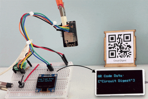
As shown above, our project seamlessly scans QR codes and displays the result on the OLED display.
How does it work?
In short, the ESP32-CAM captures images and sends them to a server with a QR code recognition program via an API request. Once the recognition is complete, the server responds with the decoded data. It's straightforward and with our QR Code Scanner API, the process is smooth and efficient.
Components Required to Build the QR Code Scanner
To demonstrate the QR Code Scanner project, I will add a push button. When the button is pressed, the ESP32-CAM will capture an image and send it to the server. Once the recognition is complete, the response from the server will be displayed on the OLED display. The required components for this QR code scanner project are as follows:
ESP32 CAM x1
0.96” OLED Display x1
Push Button x1
Any USB to UART Converter x1
Bread Board x1
Jumper Wires - Required Quantity
Circuit Diagram of QR Code Scanner Using ESP32 CAM
Here the circuit Diagram is actually straightforward with its fewer components. Below you can see the circuit diagram of the QR Code Scanner Project.

As usual, the USB to UART Module is connected to the ESP32-CAM as follows: VCC to 5V, GND to GND, TX to RX, and RX to TX. Since the ESP32-CAM does not have built-in I2C support, we use GPIO14 (SCL) and GPIO15 (SDA) to connect to the OLED display by configuring these pins as I2C using the Wire library. The OLED display will show the result. GPIO13 is used as a digital input pin for the push button, which triggers the scanning process. This GPIO13 is pulled down using a 10k resistor to maintain an active low state.

Above, you can see that all the components are assembled according to the circuit diagram. The ESP32-CAM is floating with the help of jumper wires, while the other components are connected to the breadboard. You might notice that I’m using a simple micro-USB breakout board instead of a USB to UART module. This is because I had already programmed the ESP32, and the image was taken during a working demonstration. For powering the module, I used the micro-USB breakout board. However, for proper setup, you should connect a USB to UART converter module.
Next let's move to the coding Part.
Code for ESP32 CAM Based QR Code Scanner
Finally, we came to coding part. Here there are certain prerequisites that we need to do before going directly to code.
Generating API Key
We need API key to use the QR Code Scanner API. you can get it from circuitdigest.cloud. Follow the steps below to obtain your own API Key.

Step 1: Visit the Circuit Digest Cloud website at circuitdigest.cloud. Click the "Login" button located at the top right corner to be redirected to the login page.
Step 2: If you already have an account, log in using your existing credentials. If not, go to the registration page to create an account by filling in the required details. Once completed, click "Register Now" to sign up.
Step 3: After registering, use your email ID and password to log in on the login page.

Step 4: Once logged in, click on "My Account" at the top right corner.
Step 5: You will be directed to a page where you can generate your API Key. Enter the captcha text in the provided box, then click the "Submit" button.
Step 6: If the captcha is correct, you'll see a table displaying your API Key along with its expiration date and usage count. Currently, there is a limit of 50 uses per key. Once you reach this limit, you can generate another key, giving you an additional 50 uses. This usage limit is in place to prevent server overload.
For more details about API Key, validity of api access visit our another blog explaining about QR Code Scanner API for Low-Power Embedded SoC Boards.
By this step you should get your API Key, let's use this key in our code.
Part 1: Setup and Configuration
This section includes necessary libraries and defines settings for the ESP32-CAM, OLED display, and other components. It sets up WiFi credentials, camera pins, and OLED display parameters.
#include <Arduino.h>
#include <WiFi.h>
#include <WiFiClientSecure.h>
#include "soc/soc.h"
#include "soc/rtc_cntl_reg.h"
#include "esp_camera.h"
// I2C and OLED Display Includes
#include <Wire.h>
#include <Adafruit_GFX.h>
#include <Adafruit_SSD1306.h>
// ESP32-CAM doesn't have dedicated I2C pins, so we define our own
#define I2C_SDA 15
#define I2C_SCL 14
TwoWire I2Cbus = TwoWire(0);
// Display defines
#define SCREEN_WIDTH 128
#define SCREEN_HEIGHT 64
#define OLED_RESET -1
#define SCREEN_ADDRESS 0x3C
Adafruit_SSD1306 display(SCREEN_WIDTH, SCREEN_HEIGHT, &I2Cbus, OLED_RESET);
const char* ssid = "xxx";         // Replace "xxx" with your WiFi SSID
const char* password = "xxx";      // Replace "xxx" with your WiFi Password
String serverName = "www.circuitdigest.cloud";  // Server domain
String serverPath = "/readqrcode";              // API endpoint path
const int serverPort = 443;                     // HTTPS port
String apiKey = "xxx";             // Replace "xxx" with your API key
#define triggerButton 13  // GPIO pin for the trigger button
#define flashLight 4      // GPIO pin for the flashlight
int count = 0;           // Counter for image uploads
WiFiClientSecure client; // Secure client for HTTPS communication
// Camera GPIO pins - adjust based on your ESP32-CAM board
#define PWDN_GPIO_NUM 32
#define RESET_GPIO_NUM -1
#define XCLK_GPIO_NUM 0
#define SIOD_GPIO_NUM 26
#define SIOC_GPIO_NUM 27
#define Y9_GPIO_NUM 35
#define Y8_GPIO_NUM 34
#define Y7_GPIO_NUM 39
#define Y6_GPIO_NUM 36
#define Y5_GPIO_NUM 21
#define Y4_GPIO_NUM 19
#define Y3_GPIO_NUM 18
#define Y2_GPIO_NUM 5
#define VSYNC_GPIO_NUM 25
#define HREF_GPIO_NUM 23
#define PCLK_GPIO_NUM 22
Here, necessary libraries for WiFi, HTTPS, camera, and OLED display functionalities. GPIOs are also declared here for variables such as I2C_SDA, I2C_SCL, triggerButton, and flashLight. Includes placeholders for WiFi credentials (ssid and password), server details (serverName and serverPath), and apiKey. You need to add WiFi credentials and API key. Server details can be kept unchanged.
Part 2: Initialization and Utility Functions
// Function to extract a JSON array value by key
String extractJsonArrayValue(const String& jsonString, const String& key) {
  int keyIndex = jsonString.indexOf(key);
  if (keyIndex == -1) {
    return "";
  }
  int startIndex = jsonString.indexOf('[', keyIndex);
  int endIndex = jsonString.indexOf(']', startIndex);
  if (startIndex == -1 || endIndex == -1) {
    return "";
  }
  return jsonString.substring(startIndex, endIndex + 1);
}
// Function to extract a JSON string value by key
String extractJsonStringValue(const String& jsonString, const String& key) {
  int keyIndex = jsonString.indexOf(key);
  if (keyIndex == -1) {
    return "";
  }
  int startIndex = jsonString.indexOf(':', keyIndex) + 2;
  int endIndex = jsonString.indexOf('"', startIndex);
  if (startIndex == -1 || endIndex == -1) {
    return "";
  }
  return jsonString.substring(startIndex, endIndex);
}
// Function to display text on OLED
void displayText(String text) {
  display.clearDisplay();
  display.setCursor(0, 10);
  display.setTextSize(1);
  display.setTextColor(SSD1306_WHITE);
  display.print(text);
  display.display();
}
void setup() {
  // Disable brownout detector
  WRITE_PERI_REG(RTC_CNTL_BROWN_OUT_REG, 0);
  Serial.begin(115200);
  pinMode(flashLight, OUTPUT);
  pinMode(triggerButton, INPUT);
  digitalWrite(flashLight, LOW);
  // Connect to WiFi
  WiFi.mode(WIFI_STA);
  Serial.println();
  Serial.print("Connecting to ");
  Serial.println(ssid);
  WiFi.begin(ssid, password);
  while (WiFi.status() != WL_CONNECTED) {
    Serial.print(".");
    delay(500);
  }
  Serial.println();
  Serial.print("ESP32-CAM IP Address: ");
  Serial.println(WiFi.localIP());
  // Configure camera
  camera_config_t config;
  config.ledc_channel = LEDC_CHANNEL_0;
  config.ledc_timer = LEDC_TIMER_0;
  config.pin_d0 = Y2_GPIO_NUM;
  config.pin_d1 = Y3_GPIO_NUM;
  config.pin_d2 = Y4_GPIO_NUM;
  config.pin_d3 = Y5_GPIO_NUM;
  config.pin_d4 = Y6_GPIO_NUM;
  config.pin_d5 = Y7_GPIO_NUM;
  config.pin_d6 = Y8_GPIO_NUM;
  config.pin_d7 = Y9_GPIO_NUM;
  config.pin_xclk = XCLK_GPIO_NUM;
  config.pin_pclk = PCLK_GPIO_NUM;
  config.pin_vsync = VSYNC_GPIO_NUM;
  config.pin_href = HREF_GPIO_NUM;
  config.pin_sscb_sda = SIOD_GPIO_NUM;
  config.pin_sscb_scl = SIOC_GPIO_NUM;
  config.pin_pwdn = PWDN_GPIO_NUM;
  config.pin_reset = RESET_GPIO_NUM;
  config.xclk_freq_hz = 20000000;
  config.pixel_format = PIXFORMAT_JPEG;
  // Adjust frame size and quality based on PSRAM availability
  if (psramFound()) {
    config.frame_size = FRAMESIZE_SVGA;
    config.jpeg_quality = 5;  // Lower number means higher quality (0-63)
    config.fb_count = 2;
    Serial.println("PSRAM found");
  } else {
    config.frame_size = FRAMESIZE_CIF;
    config.jpeg_quality = 12;  // Lower number means higher quality (0-63)
    config.fb_count = 1;
  }
  // Initialize camera
  esp_err_t err = esp_camera_init(&config);
  if (err != ESP_OK) {
    Serial.printf("Camera init failed with error 0x%x", err);
    delay(1000);
    ESP.restart();
  }
  // Initialize I2C with our defined pins
  I2Cbus.begin(I2C_SDA, I2C_SCL, 100000);
  // Initialize OLED display
  if (!display.begin(SSD1306_SWITCHCAPVCC, SCREEN_ADDRESS)) {
    Serial.printf("SSD1306 OLED display failed to initialize.\nCheck that display SDA is connected to pin %d and SCL connected to pin %d\n", I2C_SDA, I2C_SCL);
    while (true);
  }
  // Display initialization messages
  displayText("System Initialization Successful");
  delay(1000);
  displayText("Press Trigger Button \n\nto Start Capturing");
}
Utility Functions: Functions to extract JSON values and display text on the OLED. There are two functions available, which are extractJsonStringValue to extract string values and extractJsonArrayValue to extract array values. These are standalone functions, but you can still utilize some JSON library to do the same function.
setup() Function: Initializes the serial communication, connects to WiFi, configures the camera, and initializes the OLED display. It also disables the brownout detector and sets up the GPIO pins for the flashlight and trigger button.
Part 3: Main Operation
void loop() {
  // Check if trigger button is pressed
  if (digitalRead(triggerButton) == HIGH) {
    int status = sendPhoto();
    if (status == -1) {
      displayText("Image Capture Failed");
    } else if (status == -2) {
      displayText("Server Connection Failed");
    }
  }
}
// Function to capture and send photo to the server
int sendPhoto() {
  camera_fb_t* fb = NULL;

  // Turn on flash light and capture image
  digitalWrite(flashLight, HIGH);
  delay(1000);
  fb = esp_camera_fb_get();
  if (!fb) {
    Serial.println("Camera capture failed");
    return -1;
  }

  // Display success message
  displayText("Image Capture Success");
  delay(300);
  digitalWrite(flashLight, LOW);
  // Connect to server
  Serial.println("Connecting to server:" + serverName);
  displayText("Connecting to server:\n\n" + serverName);
  client.setInsecure();  // Skip certificate validation for simplicity
  if (client.connect(serverName.c_str(), serverPort)) {
    Serial.println("Connection successful!");
    displayText("Connection successful!");
    delay(300);
    displayText("Data Uploading !");

    // Increment count and prepare file name
    count++;
    Serial.println(count);
    String filename = apiKey + ".jpeg";
    // Prepare HTTP POST request
    String head = "--CircuitDigest\r\nContent-Disposition: form-data; name=\"imageFile\"; filename=\"" + filename + "\"\r\nContent-Type: image/jpeg\r\n\r\n";
    String tail = "\r\n--CircuitDigest--\r\n";
    uint32_t imageLen = fb->len;
    uint32_t extraLen = head.length() + tail.length();
    uint32_t totalLen = imageLen + extraLen;
    client.println("POST " + serverPath + " HTTP/1.1");
    client.println("Host: " + serverName);
    client.println("Content-Length: " + String(totalLen));
    client.println("Content-Type: multipart/form-data; boundary=CircuitDigest");
    client.println("Authorization:" + apiKey);
    client.println();
    client.print(head);
    // Send image data in chunks
    uint8_t* fbBuf = fb->buf;
    size_t fbLen = fb->len;
    for (size_t n = 0; n < fbLen; n += 1024) {
      if (n + 1024 < fbLen) {
        client.write(fbBuf, 1024);
        fbBuf += 1024;
      } else {
        size_t remainder = fbLen % 1024;
        client.write(fbBuf, remainder);
      }
    }
    client.print(tail);
    // Clean up
    esp_camera_fb_return(fb);
    displayText("Waiting For Response!");
    // Wait for server response
    String response;
    long startTime = millis();
    while (client.connected() && millis() - startTime < 10000) {
      if (client.available()) {
        char c = client.read();
        response += c;
      }
    }
    // Extract and display QR code data from response
    String qrCodeData = extractJsonArrayValue(response, "\"QR_code\"");
    String imageLink = extractJsonStringValue(response, "\"view_image\"");
    Serial.print("QR Data: ");
    Serial.println(qrCodeData);
    Serial.print("ImageLink: ");
    Serial.println(imageLink);
    displayText("QR Code Data:\n\n" + qrCodeData);
    client.stop();
    return 0;
  } else {
    Serial.println("Connection to server failed");
    return -2;
  }
}
loop() Function:
Monitors the trigger button. If pressed, it calls sendPhoto() to capture and send a photo.
sendPhoto() Function:
sendPhoto Function does 4 different tasks:
Image Capture: Turns on the flashlight, captures an image, and stores it in the framebuffer.
Server Connection: Connects to the server using secure HTTPS.
Image Upload: Prepares and sends the HTTP POST request with the captured image. To exactly understand the format of the data that needs to be sent, kindly look at the API Details.
Response Handling: Extracts QR code data from the server response and displays it on the OLED. As we know already, we will receive a JSON String from the server as a response.
Thereby, the code explanation is completed. Next, let's upload the code and test the working.
Working Demonstration of the QR Code Scanning Project
First, we need to upload the code to the ESP32-CAM. If you're unfamiliar with this process, we have a detailed article about How to Program ESP32-CAM using Arduino. Ensure that all connections are correct on the breadboard and ESP32-CAM before proceeding.
After uploading, the ESP32-CAM will attempt to connect to the specified WiFi hotspot. Ensure your hotspot credentials are correct in the code and that your hotspot is turned on.
Once the ESP32-CAM successfully connects to the hotspot, you will see an initialization message on the OLED display. When you see this message, the device is ready to capture an image. Press the trigger button, and the process will start. After a few seconds, you will be able to view the result on both the OLED display and the Serial Monitor.
Above, you can see a GIF video representing the working of the uploaded code. Note that the QR code recognition process time depends on the network speed, so reducing the image quality can increase the speed.
Conclusion
This ESP32-CAM based QR code reader project demonstrates a practical and efficient method for capturing and processing QR codes. By integrating an ESP32-CAM module with an OLED display and a secure HTTPS connection to a remote server, we have created a compact, standalone device capable of capturing images, sending them for processing, and displaying the resulting QR code data. This project showcases the potential of IoT devices in real-time data acquisition and processing, making it suitable for various applications such as inventory management, access control, and automation systems. The simplicity and effectiveness of this solution highlight the versatility of the ESP32-CAM and its capabilities in IoT projects.
Other Projects Related to QR Code scanning
1) QR Code Scanner using Raspberry Pi and OpenCV
QR codes are matrix barcodes that store information like URLs or identifiers in a 2D pattern. In this tutorial, we'll build a QR code scanner using Raspberry Pi, OpenCV, and the ZBar library to capture and decode QR codes from video frames.
2) Generate a QR code using Arduino and display it on SSD1306 OLED
QR codes have become ubiquitous in our digital lives, appearing in places like grocery stores, books, and online payments. This project will help you understand the basic concept of QR codes, how they work, and how to create and display one using an Arduino and an OLED (SSD1306) screen.


Complete Project Code
#include <Arduino.h>
#include <WiFi.h>
#include <WiFiClientSecure.h>
#include "soc/soc.h"
#include "soc/rtc_cntl_reg.h"
#include "esp_camera.h"
// I2C and OLED Display Includes
#include <Wire.h>
#include <Adafruit_GFX.h>
#include <Adafruit_SSD1306.h>
// ESP32-CAM doesn't have dedicated I2C pins, so we define our own
#define I2C_SDA 15
#define I2C_SCL 14
TwoWire I2Cbus = TwoWire(0);
// Display defines
#define SCREEN_WIDTH 128
#define SCREEN_HEIGHT 64
#define OLED_RESET -1
#define SCREEN_ADDRESS 0x3C
Adafruit_SSD1306 display(SCREEN_WIDTH, SCREEN_HEIGHT, &I2Cbus, OLED_RESET);
const char* ssid = "xxx";         // Replace "xxx" with your WiFi SSID
const char* password = "xxx";      // Replace "xxx" with your WiFi Password
String serverName = "www.circuitdigest.cloud";  // Server domain
String serverPath = "/readqrcode";              // API endpoint path
const int serverPort = 443;                     // HTTPS port
String apiKey = "xxx";             // Replace "xxx" with your API key
#define triggerButton 13  // GPIO pin for the trigger button
#define flashLight 4      // GPIO pin for the flashlight
int count = 0;           // Counter for image uploads
WiFiClientSecure client; // Secure client for HTTPS communication
// Camera GPIO pins - adjust based on your ESP32-CAM board
#define PWDN_GPIO_NUM 32
#define RESET_GPIO_NUM -1
#define XCLK_GPIO_NUM 0
#define SIOD_GPIO_NUM 26
#define SIOC_GPIO_NUM 27
#define Y9_GPIO_NUM 35
#define Y8_GPIO_NUM 34
#define Y7_GPIO_NUM 39
#define Y6_GPIO_NUM 36
#define Y5_GPIO_NUM 21
#define Y4_GPIO_NUM 19
#define Y3_GPIO_NUM 18
#define Y2_GPIO_NUM 5
#define VSYNC_GPIO_NUM 25
#define HREF_GPIO_NUM 23
#define PCLK_GPIO_NUM 22

// Function to extract a JSON array value by key
String extractJsonArrayValue(const String& jsonString, const String& key) {
  int keyIndex = jsonString.indexOf(key);
  if (keyIndex == -1) {
    return "";
  }
  int startIndex = jsonString.indexOf('[', keyIndex);
  int endIndex = jsonString.indexOf(']', startIndex);
  if (startIndex == -1 || endIndex == -1) {
    return "";
  }
  return jsonString.substring(startIndex, endIndex + 1);
}
// Function to extract a JSON string value by key
String extractJsonStringValue(const String& jsonString, const String& key) {
  int keyIndex = jsonString.indexOf(key);
  if (keyIndex == -1) {
    return "";
  }
  int startIndex = jsonString.indexOf(':', keyIndex) + 2;
  int endIndex = jsonString.indexOf('"', startIndex);
  if (startIndex == -1 || endIndex == -1) {
    return "";
  }
  return jsonString.substring(startIndex, endIndex);
}
// Function to display text on OLED
void displayText(String text) {
  display.clearDisplay();
  display.setCursor(0, 10);
  display.setTextSize(1);
  display.setTextColor(SSD1306_WHITE);
  display.print(text);
  display.display();
}
void setup() {
  // Disable brownout detector
  WRITE_PERI_REG(RTC_CNTL_BROWN_OUT_REG, 0);
  Serial.begin(115200);
  pinMode(flashLight, OUTPUT);
  pinMode(triggerButton, INPUT);
  digitalWrite(flashLight, LOW);
  // Connect to WiFi
  WiFi.mode(WIFI_STA);
  Serial.println();
  Serial.print("Connecting to ");
  Serial.println(ssid);
  WiFi.begin(ssid, password);
  while (WiFi.status() != WL_CONNECTED) {
    Serial.print(".");
    delay(500);
  }
  Serial.println();
  Serial.print("ESP32-CAM IP Address: ");
  Serial.println(WiFi.localIP());
  // Configure camera
  camera_config_t config;
  config.ledc_channel = LEDC_CHANNEL_0;
  config.ledc_timer = LEDC_TIMER_0;
  config.pin_d0 = Y2_GPIO_NUM;
  config.pin_d1 = Y3_GPIO_NUM;
  config.pin_d2 = Y4_GPIO_NUM;
  config.pin_d3 = Y5_GPIO_NUM;
  config.pin_d4 = Y6_GPIO_NUM;
  config.pin_d5 = Y7_GPIO_NUM;
  config.pin_d6 = Y8_GPIO_NUM;
  config.pin_d7 = Y9_GPIO_NUM;
  config.pin_xclk = XCLK_GPIO_NUM;
  config.pin_pclk = PCLK_GPIO_NUM;
  config.pin_vsync = VSYNC_GPIO_NUM;
  config.pin_href = HREF_GPIO_NUM;
  config.pin_sscb_sda = SIOD_GPIO_NUM;
  config.pin_sscb_scl = SIOC_GPIO_NUM;
  config.pin_pwdn = PWDN_GPIO_NUM;
  config.pin_reset = RESET_GPIO_NUM;
  config.xclk_freq_hz = 20000000;
  config.pixel_format = PIXFORMAT_JPEG;
  // Adjust frame size and quality based on PSRAM availability
  if (psramFound()) {
    config.frame_size = FRAMESIZE_SVGA;
    config.jpeg_quality = 5;  // Lower number means higher quality (0-63)
    config.fb_count = 2;
    Serial.println("PSRAM found");
  } else {
    config.frame_size = FRAMESIZE_CIF;
    config.jpeg_quality = 12;  // Lower number means higher quality (0-63)
    config.fb_count = 1;
  }
  // Initialize camera
  esp_err_t err = esp_camera_init(&config);
  if (err != ESP_OK) {
    Serial.printf("Camera init failed with error 0x%x", err);
    delay(1000);
    ESP.restart();
  }
  // Initialize I2C with our defined pins
  I2Cbus.begin(I2C_SDA, I2C_SCL, 100000);
  // Initialize OLED display
  if (!display.begin(SSD1306_SWITCHCAPVCC, SCREEN_ADDRESS)) {
    Serial.printf("SSD1306 OLED display failed to initialize.\nCheck that display SDA is connected to pin %d and SCL connected to pin %d\n", I2C_SDA, I2C_SCL);
    while (true);
  }
  // Display initialization messages
  displayText("System Initialization Successful");
  delay(1000);
  displayText("Press Trigger Button \n\nto Start Capturing");
}

void loop() {
  // Check if trigger button is pressed
  if (digitalRead(triggerButton) == HIGH) {
    int status = sendPhoto();
    if (status == -1) {
      displayText("Image Capture Failed");
    } else if (status == -2) {
      displayText("Server Connection Failed");
    }
  }
}
// Function to capture and send photo to the server
int sendPhoto() {
  camera_fb_t* fb = NULL;

  // Turn on flash light and capture image
  digitalWrite(flashLight, HIGH);
  delay(1000);
  fb = esp_camera_fb_get();
  if (!fb) {
    Serial.println("Camera capture failed");
    return -1;
  }

  // Display success message
  displayText("Image Capture Success");
  delay(300);
  digitalWrite(flashLight, LOW);
  // Connect to server
  Serial.println("Connecting to server:" + serverName);
  displayText("Connecting to server:\n\n" + serverName);
  client.setInsecure();  // Skip certificate validation for simplicity
  if (client.connect(serverName.c_str(), serverPort)) {
    Serial.println("Connection successful!");
    displayText("Connection successful!");
    delay(300);
    displayText("Data Uploading !");

    // Increment count and prepare file name
    count++;
    Serial.println(count);
    String filename = apiKey + ".jpeg";
    // Prepare HTTP POST request
    String head = "--CircuitDigest\r\nContent-Disposition: form-data; name=\"imageFile\"; filename=\"" + filename + "\"\r\nContent-Type: image/jpeg\r\n\r\n";
    String tail = "\r\n--CircuitDigest--\r\n";
    uint32_t imageLen = fb->len;
    uint32_t extraLen = head.length() + tail.length();
    uint32_t totalLen = imageLen + extraLen;
    client.println("POST " + serverPath + " HTTP/1.1");
    client.println("Host: " + serverName);
    client.println("Content-Length: " + String(totalLen));
    client.println("Content-Type: multipart/form-data; boundary=CircuitDigest");
    client.println("Authorization:" + apiKey);
    client.println();
    client.print(head);
    // Send image data in chunks
    uint8_t* fbBuf = fb->buf;
    size_t fbLen = fb->len;
    for (size_t n = 0; n < fbLen; n += 1024) {
      if (n + 1024 < fbLen) {
        client.write(fbBuf, 1024);
        fbBuf += 1024;
      } else {
        size_t remainder = fbLen % 1024;
        client.write(fbBuf, remainder);
      }
    }
    client.print(tail);
    // Clean up
    esp_camera_fb_return(fb);
    displayText("Waiting For Response!");
    // Wait for server response
    String response;
    long startTime = millis();
    while (client.connected() && millis() - startTime < 10000) {
      if (client.available()) {
        char c = client.read();
        response += c;
      }
    }
    // Extract and display QR code data from response
    String qrCodeData = extractJsonArrayValue(response, "\"QR_code\"");
    String imageLink = extractJsonStringValue(response, "\"view_image\"");
    Serial.print("QR Data: ");
    Serial.println(qrCodeData);
    Serial.print("ImageLink: ");
    Serial.println(imageLink);
    displayText("QR Code Data:\n\n" + qrCodeData);
    client.stop();
    return 0;
  } else {
    Serial.println("Connection to server failed");
    return -2;
  }
}
