

The "Quick Response" code or abbreviated as QR code has become an essential part of our digital lives, chances are that you're already subconsciously familiar with them by now you've probably been roaming around your local grocery store, or maybe you are reading through your favourite book, or even possibly you are making an online payment with Google Pay, PhonePe or Paytm, or surfing the web, etc. (I suppose I could go on and on with examples huh?) and you happened to have come across this weird looking square thing and thought, what is this square thing anyway and if you haven’t...well, don’t worry it’s bound to happen sooner or later, so to understand the topic better we are going to do a fun little project with Arduino and OLED and demystify the following things:
- Basic Concept of the QR code.
- How it works.
- How to make your very own QR code using Arduino.
- And finally, display it in an OLED (SSD1306) screen.
So, What is this QR Code Anyway?
QR code (Quick Response code) is a matrix 2D code for reading data at high speed, developed by DENSO WAVE in 1994 for the automotive industry of Japan. A QR code compresses data very efficiently compared to the standard barcode, to achieve this it uses four standardized encoding modes (numeric, alphanumeric, byte/binary, and kanji), the technology was made "open source” i.e. available for everyone so, it gained popularity very rapidly. Significant advantages of QR Codes over conventional barcodes are larger data capacity and high fault tolerance.

How QR Code Works?
QR codes (and other data matrix codes) are designed to be read by special tools, not by humans, so there's only a specific amount we can understand by studying visually, although every code is different in various ways though they contain a few interesting common features by observing the circuitdigest.com QR code we will study some of them
- Finder Patterns: Large square boxes with a solid box inside in the three corners of the code make it easy to confirm that it’s a QR code since there are only three of them, so it's pretty obvious that in which way the code is oriented.
- Alignment Pattern: This makes it certain that whatever the orientation the code can be readable.
- Timing Pattern: This runs horizontally and vertically between the three finder patterns, using these lines the reader can determine the size of the code.
- Version Information: There are currently 40 different versions of the QR code standard, this section of the code determines the QR code version which is being used, for marketing version 1-7 used normally.
- Format Information: The format partners have information about error tolerance and data masking.
- Data Area: This section of the code contains all the data elements and error correction code along.
- Quit Zone: The spacing in every QR code is mandatory in order to differentiate the code from its surroundings.
The image below will give you a clear idea about the code

Other sections of the code are data and redundancy code.
There are a number of other features and complicated topics that I won't be discussing in this tutorial, if you do like to read in more details about the QR code please follow this QR Code tutorial by Tan Jin Soon, EPCglobal Singapore Council. Synthesis Journal, 2008.
The Specification of the QR Code
|
Symbol Size |
Min. 21x21 cell - Max. 177x177 cell (with 4-cells interval) |
|
|
Information Type and Volume |
Numeric Characters |
7,089 characters at maximum |
|
Alphabets, Signs |
4,296 characters at maximum |
|
|
Binary (8 bit) |
2,953 characters at maximum |
|
|
Kanji Characters |
1,817 characters at maximum |
|
|
Conversion efficiency
|
Numeric Characters Mode |
3.3 cells/character |
|
Alphanumeric/Signs Mode |
5.5 cells/character |
|
|
Binary (8 bit) Mode |
8 cells/character |
|
|
Kanji Characters Mode (13 bit) |
13 cells/character |
|
|
Error correction functionality |
Level L |
Approx. 7% of the symbol area restored at maximum |
|
Level M |
Approx. 15% of the symbol area restored at maximum |
|
|
Level Q |
Approx. 25% of the symbol area restored at maximum |
|
|
Level H |
Approx. 30% of the symbol area restored at maximum |
|
|
Linking functionality
|
Possible to be divided into 16 symbols at maximum |
|
Generating your very own QR code
Follow the steps mentioned below to generate your very own QR code, in this example, we are going to make a QR code of our beloved Circuit Digest website
To generate a QR code go to this website and if you look at the top side of the website you can see a list of options, in this tutorial we are generating a QR code for a URL, so we are going to
- Click on the URL tab and paste the URL for the Circuit Digest in the Enter URL section.
- Click on save.
- Give a file name for the output file.
- Select PNG as our preferred file format.
- and click save.
The image below will give you a clear idea about the process

Our dearest microcontroller “Arduino” is not that intelligent enough that it could just compile the raw PNG image and displays it in the OLED display. So, to display the QR code to the OLED we need to follow some simple steps and convert the PNG image to a bitmap array readable by Arduino. This conversion we have previously done while interfacing SSD1306 OLED with Arduino and interfacing Graphical LCD with Arduino. We also interfaced SSD1306 OLED with Raspberry Pi, ESP32, NodeMCU, and many other microcontrollers. Bitmap array conversion can be done in below two steps:
- Converting the PNG to BMP format.
- Convert the BMP image to an array of HEX codes.
Converting the PNG to BMP format
To convert the downloaded PNG image to BMP image, go to this website and in the image converter section and
- Click on the dropdown menu and select
- Convert to BMP
- Click Go
The image below will give you a clear idea about the process:

You will be presented with a new page looks like the below image:

- Click on the Choose Files tab and select the downloaded image
- In the Optional settings, panel type your desired size (we are using a 128x64 OLED)
- Click on Start conversion button
You will be presented with the following page and after a few seconds your converted image will be downloaded if the download doesn't start automatically click on the download your file option:

Great! Now we got our BMP file its time to convert it to an array of HEX codes readable by an Arduino.
Convert the BMP image to an array of HEX codes
To convert the downloaded BMP image to a HEX array, go to this website and click on Tools -> image2cpp
The image below will give you a clear idea about the process

You will be presented with a screen which has four options and we will discuss them in details
- Select image
- Image Settings
- Preview
- Output
Select image section
In this section we will select the image which we have just converted to BMP:
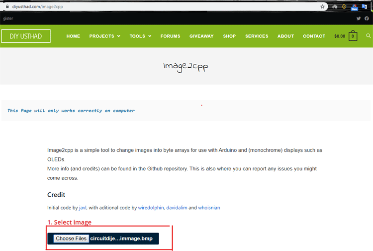
Image Settings Section
In this section, we will set the canvas size, background color, scaling and centre options to our required value.
- Canvas size (we set to 128x64 because we are using an OLED with 128x64 pixel density).
- In this section, we can set the background color of the OLED (we choose it to be white).
- Scaling is set to the original size.
- Finally, in the centre option click on the horizontal and vertical checkboxes, this will make the image appear in the centre.
The image below will give you a clear idea

Preview Section
In the preview section we can see a clear preview of the image which will be displayed in the OLED like shown below:

Output Section
In the output section we will generate and copy the generated code, to do so follow the below steps:
- Code output format (we set it as Arduino code because we are using one).
- Identifier (this option sets the name for the generated array we leave it default as it is).
- Draw mode (We set the draw mode option to horizontal).
- And finally, we click on the generate code button this will generate the final output code.
The image below will give you a clear idea

Circuit Diagram
Below image shown the interfacing connections between Arduino Nano and SSD1306:

|
Arduino Nano Pin |
OLED PIN |
|
GND |
GND |
|
3.3V |
VCC |
|
D13 |
CLK |
|
D11 |
MOSI |
|
D8 |
RES |
|
D9 |
SDC |
|
D10 |
CCS |
Code Explanation
To show the image on the OLED we need the help of an Arduino library, which can be downloaded from this GitHub repository. Download the U8glib-1.19.1.zip version of the library and import it in the Arduino IDE. If you are new to Arduino then take the help of this link describing how to import a library. In the below section we will modify the code to display the previously generated HEX array to the OLED. Complete code with a working video is given at the end of this article. The Detail Explanation of the code is given below.
First, include the downloaded library.
#include "U8glib.h" // including the U8glib library
Then define all the necessary pins for OLED.
#define OLED_CLK_PIN 13  //Arduino Digital Pin D13: SCK
#define OLED_MOSI_PIN 11 //Arduino Digital Pin D11: MOSI
#define OLED_RES_PIN 10 //Arduino Digital Pin D10: SS
#define OLED_SDC_PIN 9  //Arduino Digital Pin D9: OC1A
#define OLED_CSS_PIN 8 //Arduino Digital Pin D13: ICP1
Initialize the u8glib Library.
U8GLIB_SH1106_128X64 u8g(OLED_CLK_PIN, OLED_MOSI_PIN, OLED_RES_PIN, OLED_SDC_PIN, OLED_CSS_PIN);
Then Include the generated image array.
const uint8_t circuitdigest[] PROGMEM = {
  0xff, 0xff, 0xff, 0xff, 0xff, 0xff, 0xff, 0xff, 0xff, 0xff, 0xff, 0xff, 0xff, 0xff, 0xff, 0xff,
  0xff, 0xff, 0xff, 0xff, 0xff, 0xff, 0xff, 0xff, 0xff, 0xff, 0xff, 0xff, 0xff, 0xff, 0xff, 0xff,
  0xff, 0xff, 0xff, 0xff, 0xff, 0xff, 0xff, 0xff, 0xff, 0xff, 0xff, 0xff, 0xff, 0xff, 0xff, 0xff,
  0xff, 0xff, 0xff, 0xff, 0xff, 0xff, 0xff, 0xff, 0xff, 0xff, 0xff, 0xff, 0xff, 0xff, 0xff, 0xff,
  0xff, 0xff, 0xff, 0xff, 0xf0, 0x00, 0x1c, 0x01, 0x87, 0xf0, 0x00, 0x0f, 0xff, 0xff, 0xff, 0xff,
  0xff, 0xff, 0xff, 0xff, 0xf0, 0x00, 0x0c, 0x01, 0x87, 0xf0, 0x00, 0x0f, 0xff, 0xff, 0xff, 0xff,
  0xff, 0xff, 0xff, 0xff, 0xf3, 0xff, 0x8f, 0xf0, 0x7f, 0x31, 0xff, 0x8f, 0xff, 0xff, 0xff, 0xff,
  0xff, 0xff, 0xff, 0xff, 0xf3, 0xff, 0x8f, 0xf0, 0x7f, 0x33, 0xff, 0xcf, 0xff, 0xff, 0xff, 0xff,
  0xff, 0xff, 0xff, 0xff, 0xf3, 0x81, 0x8f, 0x31, 0x80, 0x33, 0x81, 0xcf, 0xff, 0xff, 0xff, 0xff,
  0xff, 0xff, 0xff, 0xff, 0xf3, 0x01, 0x8f, 0x31, 0x80, 0x33, 0x81, 0xcf, 0xff, 0xff, 0xff, 0xff,
  0xff, 0xff, 0xff, 0xff, 0xf3, 0x01, 0x8f, 0xb1, 0x80, 0x33, 0x81, 0xcf, 0xff, 0xff, 0xff, 0xff,
  0xff, 0xff, 0xff, 0xff, 0xf3, 0x01, 0x8f, 0xc1, 0x98, 0x33, 0x81, 0xcf, 0xff, 0xff, 0xff, 0xff,
  0xff, 0xff, 0xff, 0xff, 0xf3, 0x01, 0x8f, 0xc1, 0x98, 0x33, 0x81, 0xcf, 0xff, 0xff, 0xff, 0xff,
……..
………..
Draw function is used to draw the bitmap image (QR code) on OLED with the help of u8g.drawBitmapP function.
void draw(void) {
  // graphic commands to redraw the complete screen should be placed here
  u8g.drawBitmapP( 0, 0, 16, 64, circuitdigest);
…..
……
Finally, in loop() function, call all the necessary procedures to build the image on OLED
void loop() {
  u8g.firstPage();  //A call to this procedure, marks the beginning of the picture loop.
  do {
    draw();
  } while( u8g.nextPage() ); // A call to this procedure, marks the end of the body of the picture loop.
  // rebuild the picture after some delay
  delay(1000);
}
After completing the code, plug in the Arduino in the USB port of your computer, select your COM port and upload the code. If you have done everything correctly you will have a working display with a QR code on OLED.

I hope you liked this project and enjoyed learning something new, keep reading keep learning and I will see you next time.
Complete Project Code
/*
  Universal 8bit Graphics Library, http://code.google.com/p/u8glib/
*/
#include "U8glib.h" // including the U8glib library
#define OLED_CLK_PIN 13  //Arduino Digital Pin D13: SCK
#define OLED_MOSI_PIN 11 //Arduino Digital Pin D11: MOSI
#define OLED_RES_PIN 10 //Arduino Digital Pin D10: SS
#define OLED_SDC_PIN 9  //Arduino Digital Pin D9: OC1A
#define OLED_CSS_PIN 8 //Arduino Digital Pin D13: ICP1
U8GLIB_SH1106_128X64 u8g(OLED_CLK_PIN, OLED_MOSI_PIN, OLED_RES_PIN, OLED_SDC_PIN, OLED_CSS_PIN);
/*
   make an object of the U8GLIB_SH1106_128X64 class and initialized the Pins of the arduino
   this method takes five arguments first (SCK_PIN,MOSI_PIN,CS_PIN,A0_pin,RESET_PIN)
*/
//the custom made circuitdigest Bitmap
const uint8_t circuitdigest[] PROGMEM = {
  0xff, 0xff, 0xff, 0xff, 0xff, 0xff, 0xff, 0xff, 0xff, 0xff, 0xff, 0xff, 0xff, 0xff, 0xff, 0xff,
  0xff, 0xff, 0xff, 0xff, 0xff, 0xff, 0xff, 0xff, 0xff, 0xff, 0xff, 0xff, 0xff, 0xff, 0xff, 0xff,
  0xff, 0xff, 0xff, 0xff, 0xff, 0xff, 0xff, 0xff, 0xff, 0xff, 0xff, 0xff, 0xff, 0xff, 0xff, 0xff,
  0xff, 0xff, 0xff, 0xff, 0xff, 0xff, 0xff, 0xff, 0xff, 0xff, 0xff, 0xff, 0xff, 0xff, 0xff, 0xff,
  0xff, 0xff, 0xff, 0xff, 0xf0, 0x00, 0x1c, 0x01, 0x87, 0xf0, 0x00, 0x0f, 0xff, 0xff, 0xff, 0xff,
  0xff, 0xff, 0xff, 0xff, 0xf0, 0x00, 0x0c, 0x01, 0x87, 0xf0, 0x00, 0x0f, 0xff, 0xff, 0xff, 0xff,
  0xff, 0xff, 0xff, 0xff, 0xf3, 0xff, 0x8f, 0xf0, 0x7f, 0x31, 0xff, 0x8f, 0xff, 0xff, 0xff, 0xff,
  0xff, 0xff, 0xff, 0xff, 0xf3, 0xff, 0x8f, 0xf0, 0x7f, 0x33, 0xff, 0xcf, 0xff, 0xff, 0xff, 0xff,
  0xff, 0xff, 0xff, 0xff, 0xf3, 0x81, 0x8f, 0x31, 0x80, 0x33, 0x81, 0xcf, 0xff, 0xff, 0xff, 0xff,
  0xff, 0xff, 0xff, 0xff, 0xf3, 0x01, 0x8f, 0x31, 0x80, 0x33, 0x81, 0xcf, 0xff, 0xff, 0xff, 0xff,
  0xff, 0xff, 0xff, 0xff, 0xf3, 0x01, 0x8f, 0xb1, 0x80, 0x33, 0x81, 0xcf, 0xff, 0xff, 0xff, 0xff,
  0xff, 0xff, 0xff, 0xff, 0xf3, 0x01, 0x8f, 0xc1, 0x98, 0x33, 0x81, 0xcf, 0xff, 0xff, 0xff, 0xff,
  0xff, 0xff, 0xff, 0xff, 0xf3, 0x01, 0x8f, 0xc1, 0x98, 0x33, 0x81, 0xcf, 0xff, 0xff, 0xff, 0xff,
  0xff, 0xff, 0xff, 0xff, 0xf3, 0x01, 0x8f, 0xc0, 0x67, 0x33, 0x81, 0xcf, 0xff, 0xff, 0xff, 0xff,
  0xff, 0xff, 0xff, 0xff, 0xf3, 0x01, 0x8f, 0xc0, 0x67, 0x33, 0x81, 0xcf, 0xff, 0xff, 0xff, 0xff,
  0xff, 0xff, 0xff, 0xff, 0xf3, 0xff, 0x8f, 0x31, 0xe7, 0x33, 0xff, 0xcf, 0xff, 0xff, 0xff, 0xff,
  0xff, 0xff, 0xff, 0xff, 0xf3, 0xff, 0x8f, 0x31, 0xe7, 0x33, 0xff, 0xcf, 0xff, 0xff, 0xff, 0xff,
  0xff, 0xff, 0xff, 0xff, 0xf0, 0x00, 0x0c, 0xce, 0x67, 0x30, 0x00, 0x0f, 0xff, 0xff, 0xff, 0xff,
  0xff, 0xff, 0xff, 0xff, 0xf0, 0x00, 0x0c, 0xce, 0x67, 0x30, 0x00, 0x0f, 0xff, 0xff, 0xff, 0xff,
  0xff, 0xff, 0xff, 0xff, 0xf8, 0x00, 0x1c, 0x4e, 0x27, 0x38, 0x00, 0x1f, 0xff, 0xff, 0xff, 0xff,
  0xff, 0xff, 0xff, 0xff, 0xff, 0xff, 0xfc, 0x3e, 0x1f, 0x3f, 0xff, 0xff, 0xff, 0xff, 0xff, 0xff,
  0xff, 0xff, 0xff, 0xff, 0xff, 0xff, 0xfc, 0x3e, 0x1e, 0x3f, 0xff, 0xff, 0xff, 0xff, 0xff, 0xff,
  0xff, 0xff, 0xff, 0xff, 0xf0, 0xe1, 0x8f, 0x3e, 0x60, 0x33, 0xff, 0xcf, 0xff, 0xff, 0xff, 0xff,
  0xff, 0xff, 0xff, 0xff, 0xf0, 0xe1, 0x8f, 0x3e, 0x60, 0x33, 0xff, 0xcf, 0xff, 0xff, 0xff, 0xff,
  0xff, 0xff, 0xff, 0xff, 0xff, 0x19, 0xf0, 0xcf, 0xf8, 0xfc, 0x00, 0x3f, 0xff, 0xff, 0xff, 0xff,
  0xff, 0xff, 0xff, 0xff, 0xff, 0x19, 0xf0, 0xcf, 0xf8, 0xfc, 0x00, 0x3f, 0xff, 0xff, 0xff, 0xff,
  0xff, 0xff, 0xff, 0xff, 0xf0, 0xff, 0x83, 0x3e, 0x00, 0xcc, 0x67, 0xcf, 0xff, 0xff, 0xff, 0xff,
  0xff, 0xff, 0xff, 0xff, 0xf0, 0xff, 0x83, 0x3e, 0x00, 0xcc, 0x67, 0xcf, 0xff, 0xff, 0xff, 0xff,
  0xff, 0xff, 0xff, 0xff, 0xff, 0x00, 0x7c, 0xff, 0xc3, 0xf1, 0xe0, 0x0f, 0xff, 0xff, 0xff, 0xff,
  0xff, 0xff, 0xff, 0xff, 0xff, 0x00, 0x7c, 0xff, 0xe7, 0xf3, 0xe0, 0x0f, 0xff, 0xff, 0xff, 0xff,
  0xff, 0xff, 0xff, 0xff, 0xff, 0x00, 0x7c, 0xff, 0xe7, 0xf1, 0xe0, 0x0f, 0xff, 0xff, 0xff, 0xff,
  0xff, 0xff, 0xff, 0xff, 0xf0, 0xf9, 0x8f, 0x0e, 0x78, 0xf0, 0x7f, 0xcf, 0xff, 0xff, 0xff, 0xff,
  0xff, 0xff, 0xff, 0xff, 0xf0, 0xf9, 0x8f, 0x0e, 0x78, 0xf0, 0x7f, 0xcf, 0xff, 0xff, 0xff, 0xff,
  0xff, 0xff, 0xff, 0xff, 0xf3, 0x19, 0xf3, 0xce, 0x18, 0x0f, 0x9e, 0x3f, 0xff, 0xff, 0xff, 0xff,
  0xff, 0xff, 0xff, 0xff, 0xf3, 0x19, 0xe3, 0xce, 0x18, 0x0f, 0x9e, 0x3f, 0xff, 0xff, 0xff, 0xff,
  0xff, 0xff, 0xff, 0xff, 0xf0, 0x07, 0x83, 0x0f, 0x80, 0xf3, 0x80, 0x0f, 0xff, 0xff, 0xff, 0xff,
  0xff, 0xff, 0xff, 0xff, 0xf0, 0x07, 0x83, 0x0f, 0x80, 0xf3, 0x80, 0x0f, 0xff, 0xff, 0xff, 0xff,
  0xff, 0xff, 0xff, 0xff, 0xf1, 0xc7, 0xe0, 0xf3, 0xe3, 0x7c, 0x40, 0x8f, 0xff, 0xff, 0xff, 0xff,
  0xff, 0xff, 0xff, 0xff, 0xf3, 0xe7, 0xf0, 0xf1, 0xe7, 0x3c, 0x61, 0xcf, 0xff, 0xff, 0xff, 0xff,
  0xff, 0xff, 0xff, 0xff, 0xf3, 0xe7, 0xf0, 0xf9, 0xe7, 0x3c, 0x60, 0xcf, 0xff, 0xff, 0xff, 0xff,
  0xff, 0xff, 0xff, 0xff, 0xf3, 0x19, 0x8c, 0x3e, 0x07, 0x00, 0x18, 0x3f, 0xff, 0xff, 0xff, 0xff,
  0xff, 0xff, 0xff, 0xff, 0xf3, 0x39, 0x9c, 0x3e, 0x07, 0x00, 0x18, 0x3f, 0xff, 0xff, 0xff, 0xff,
  0xff, 0xff, 0xff, 0xff, 0xff, 0xff, 0xfc, 0x3e, 0x1f, 0x3f, 0x98, 0x3f, 0xff, 0xff, 0xff, 0xff,
  0xff, 0xff, 0xff, 0xff, 0xff, 0xff, 0xfc, 0x3e, 0x1f, 0x3f, 0x98, 0x3f, 0xff, 0xff, 0xff, 0xff,
  0xff, 0xff, 0xff, 0xff, 0xf0, 0x00, 0x1f, 0x01, 0xff, 0x33, 0x9f, 0xcf, 0xff, 0xff, 0xff, 0xff,
  0xff, 0xff, 0xff, 0xff, 0xf0, 0x00, 0x0f, 0x01, 0xff, 0x33, 0x9f, 0xcf, 0xff, 0xff, 0xff, 0xff,
  0xff, 0xff, 0xff, 0xff, 0xf1, 0xff, 0x8f, 0xc7, 0x80, 0x3f, 0x9f, 0xff, 0xff, 0xff, 0xff, 0xff,
  0xff, 0xff, 0xff, 0xff, 0xf3, 0xff, 0x8f, 0xcf, 0x80, 0x3f, 0x9f, 0xff, 0xff, 0xff, 0xff, 0xff,
  0xff, 0xff, 0xff, 0xff, 0xf3, 0xff, 0x8f, 0xcf, 0x80, 0x3f, 0x1f, 0xff, 0xff, 0xff, 0xff, 0xff,
  0xff, 0xff, 0xff, 0xff, 0xf3, 0x01, 0x8c, 0x30, 0x60, 0x00, 0x1f, 0xff, 0xff, 0xff, 0xff, 0xff,
  0xff, 0xff, 0xff, 0xff, 0xf3, 0x01, 0x8c, 0x30, 0x60, 0x00, 0x1f, 0xff, 0xff, 0xff, 0xff, 0xff,
  0xff, 0xff, 0xff, 0xff, 0xf3, 0x01, 0x8c, 0xf1, 0xe0, 0x03, 0xfe, 0x0f, 0xff, 0xff, 0xff, 0xff,
  0xff, 0xff, 0xff, 0xff, 0xf3, 0x01, 0x8c, 0xf1, 0xe0, 0x03, 0xfe, 0x0f, 0xff, 0xff, 0xff, 0xff,
  0xff, 0xff, 0xff, 0xff, 0xf3, 0x01, 0x8f, 0xc1, 0x83, 0xcf, 0x80, 0x0f, 0xff, 0xff, 0xff, 0xff,
  0xff, 0xff, 0xff, 0xff, 0xf3, 0x01, 0x8f, 0xc1, 0x87, 0xcf, 0x80, 0x0f, 0xff, 0xff, 0xff, 0xff,
  0xff, 0xff, 0xff, 0xff, 0xf3, 0xff, 0x8c, 0xff, 0xe1, 0xc0, 0x18, 0x0f, 0xff, 0xff, 0xff, 0xff,
  0xff, 0xff, 0xff, 0xff, 0xf3, 0xff, 0x8c, 0xff, 0xe0, 0xc0, 0x18, 0x0f, 0xff, 0xff, 0xff, 0xff,
  0xff, 0xff, 0xff, 0xff, 0xf1, 0xff, 0x8c, 0xff, 0xf0, 0xc0, 0x18, 0x0f, 0xff, 0xff, 0xff, 0xff,
  0xff, 0xff, 0xff, 0xff, 0xf0, 0x00, 0x0c, 0x0e, 0x7f, 0x3f, 0xe7, 0xcf, 0xff, 0xff, 0xff, 0xff,
  0xff, 0xff, 0xff, 0xff, 0xf0, 0x00, 0x1c, 0x0e, 0x7f, 0x3f, 0xe7, 0xcf, 0xff, 0xff, 0xff, 0xff,
  0xff, 0xff, 0xff, 0xff, 0xff, 0xff, 0xff, 0xff, 0xff, 0xff, 0xff, 0xff, 0xff, 0xff, 0xff, 0xff,
  0xff, 0xff, 0xff, 0xff, 0xff, 0xff, 0xff, 0xff, 0xff, 0xff, 0xff, 0xff, 0xff, 0xff, 0xff, 0xff,
  0xff, 0xff, 0xff, 0xff, 0xff, 0xff, 0xff, 0xff, 0xff, 0xff, 0xff, 0xff, 0xff, 0xff, 0xff, 0xff,
  0xff, 0xff, 0xff, 0xff, 0xff, 0xff, 0xff, 0xff, 0xff, 0xff, 0xff, 0xff, 0xff, 0xff, 0xff, 0xff
};
void draw(void) {
  // graphic commands to redraw the complete screen should be placed here
  u8g.drawBitmapP( 0, 0, 16, 64, circuitdigest);
  /*
    drawBitmapP Method takes five arguments
    First: X-position (left position of the bitmap).
    Secound: Y-position (upper position of the bitmap).
    Third: Number of bytes of the bitmap in horizontal direction. The width of the bitmap is cnt/8.
    Fourth: Height of the bitmap.
    Fifth: Bitmap array.
  */
  /*
    Draw a bitmap at the specified x/y position (upper left corner of the bitmap).
    Parts of the bitmap may be outside the display boundaries.The bitmap is specified by the array bitmap.
    A cleared bit means: Do not draw a pixel.
    A set bit inside the array means: Write pixel with the current color index.For a monochrome display,
    the color index 0 will usually clear a pixel and the color index 1 will set a pixel.
  */
}
void setup() {
  //  empty setup function as the library manages all internally
}
void loop() {
  u8g.firstPage();  //A call to this procedure, marks the beginning of the picture loop.
  do {
    draw();
  } while( u8g.nextPage() ); // A call to this procedure, marks the end of the body of the picture loop.
  // rebuild the picture after some delay
  delay(1000);
}
