 Anand D
Author

In this project, we build a complete ESP32 GSM voice calling device using the GeoLinker GL868 board. The main idea of this project is very simple. When we press a push button connected to the ESP32 board, it will automatically call a fixed phone number. Also, if someone calls the SIM card inside the module, the call will be automatically attended, and we can talk through the connected microphone and speaker.
For this project, we are using the GeoLinker GL868 board because it already has an ESP32 controller and a SIM868 GSM module on the same board. This makes it much easier since we do not need to separately connect a GSM module and ESP32. GL868 can be useful for making simple communication systems, emergency calling devices, wireless intercom systems, security systems and many other GSM-based applications. The GeoLinker GL868 development board has a well-documented Wiki Page where you can find out the whole functionalities and specs of the board.
Quick Overview
| Parameters Used | Details |
| Main Board | GeoLinker GL868 (ESP32-S3 + SIM868) |
| GSM Module | SIM868 (2G GSM/GPRS + GPS) |
| Trigger | Push button on GPIO 4 |
| Audio Output | 4Ω Speaker on SP+ / SP– pins (max 1 W at 8Ω) |
| Audio Input | Condenser microphone on M+ / M– pins |
| Power Supply | 3.7V Li-ion battery via JST connector |
| SIM Type | 2G GSM SIM with active voice plan |
| Auto-Answer | Yes - detects RING, sends ATA command |
Table of Contents
Introduction to GeoLinker GL868
The GeoLinker GL868_ESP32 is a production-ready, open-source development board that combines an ESP32-S3 and SIM868 GSM modem, with GPS Tracking, motion detection, battery management, wireless connectivity (Bluetooth/Wifi) and cellular monitoring (GPRS/SMS/Calls) on a compact PCB. It targets asset tracking, vehicle monitoring, anti-theft systems, and any IoT application that needs cellular monitoring or control, along with location tracking. This kind of GSM-based communication system project is highly practical and can serve as the foundation for a GSM-based emergency calling device for elderly care, a wireless calling device using GSM for industrial alerts, or a GSM auto-dialer for alarm systems.
The board ships with an Airtel M2M IoT SIM card (optional) and readily supports the GeoLinker GPS tracking dashboard, allowing you to track and visualise data on a map right out of the box for quick prototyping. For further development, you can use the open-source GL868_ESP32 Arduino library, which provides a high-level, non-blocking API for GPS tracking, HTTP data upload, SMS command processing, voice call handling, and deep-sleep power management. To give you a further understanding of the Geolinker GL868 Development Board, here is another tutorial on how we can use GL868 to make an IVR System.
How the ESP32 GSM Calling System Works
The working of this project is very easy. We have a button connected to GPIO 4 of GL868. Once this button is pressed, the if condition in loop() turns true, and it sends AT commands to place a call to the configured number. The SIM868 GSM Modem takes care of the call and gives audio output through the SP+ and SP- pins to which we have connected our 4Ω speaker. The condenser mic is connected to the M+ and M- pins, which give audio input to the modem.
For incoming calls, the Modem sends a message “RING” to ESP32, which keeps on repeating until the call is automatically answered by the AT command sent by ESP32 to the Modem. The call goes on until disconnected from the other end. Both incoming and outgoing calls function normally as we call normally using cell phones. We can add multiple buttons as well, which point the call to different end points/users.
This tutorial introduces you to the SIM868 GSM Modem. If you like to get started with another version, do check-out our GSM based calling and texting project using SIM900A. If you need to make use of a Raspberry Pi in your project while taking advantage of a GSM Module, here is our Call and Text using Raspberry Pi and GSM Module project, where we showcased how a GSM module can be integrated with a RPI4.
Circuit Diagram
Below is the detailed circuit diagram for this project.

Circuit Connections at a Glance
The circuit diagram is very simple. We have a small speaker connected to the SP+ and SP- pins of the board. The condenser mic is connected to the M+ and M- pins of the board. The push button is connected to the pulled-up GPIO 4 of the board. When the button is pressed. It connects GPIO 4 to GND, and it places the call to the assigned number. The antennas are GSM and GPS antennas are kept in an upward position. The speaker pins give an output of max 1Watt with 8Ω impedance. Here in this tutorial, I’ve used a mini enclosed speaker with 4Ω impedance. The 3.7V lithium battery is connected to the board using the JST connector provided on the backside of the board.
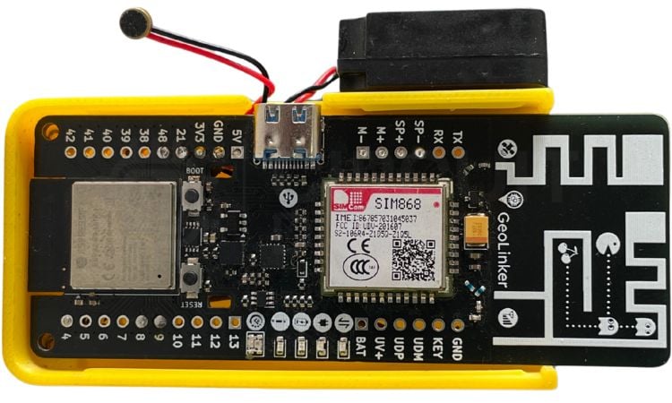
Above is the real hardware setup of the project, kept in a 3D-Printed enclosure. The enclosure is designed to properly keep the battery and wires in a well-organised way.
SIM868 AT Commands Used in This Project
The SIM868 modem is controlled by the ESP32 through Serial2 using standard Hayes AT commands, which allows for communication between the two devices. A complete list of the AT commands that are being utilised in this project is provided in the table below. It is recommended that you use this table as a reference for all your GSM voice communication projects using the ESP32.
| AT Command | Purpose |
| AT+CHFA=1 | Select audio channel 1 (external speaker/mic on GPIO pins) |
| AT+CLVL=90 | Set speaker/loudspeaker volume level |
| AT+CMIC=0,12 | Set microphone gain for channel 0 |
| AT+FMMUTE=0 | Unmute the audio path |
| AT+SIDET=1 | Enable sidetone (hear your own voice feedback) |
| ATD+[number]; | Dial a voice call (semicolon ensures voice, not data) |
| ATA | Answer an incoming call (auto-answer on RING detection) |
| ATH | Hang up / end the current call |
Components Required
Below is the list of components required to build this project with their description.
| S No | Component | Description |
| 1. | GeoLinker GL868 dev board | The main controller for the project |
| 2. | 4Ω Speaker | To get the audio output |
| 3. | Condenser mic | To give audio input to the device |
| 4. | 3.7 V lithium battery | To power the whole project |
| 5. | Push Button | To trigger a call on button press |
| 6. | SIM Card | 2G SIM card for connectivity |
| 7. | Connecting wires | To make the whole circuit |
Code Explanation
Below is a detailed breakdown of the whole code in detail, so you can learn the functionalities this code gives to our project.
Configuration Section
#define DEVICE_ID "GL868_ESP32"
#define API_KEY "cd_har_270526_LUOh63"
#define BUTTON_PIN 4
const char* phoneNumber = "+919744041489";
DEVICE_ID & API_KEY: Credentials to connect to the GeoLinker cloud service. You can give the DEVICE_ID a name that you can easily identify. Here, I have given GL868_ESP32.
For API_KEY, you need to go to CircuitDigest Cloud > Login/Create an Account > API Keys > Copy the API Key displayed in the dashboard and paste it here
BUTTON_PIN 4: GPIO pin where the push button is connected (with a pull-up resistor)
Phone Number: The emergency number that will be dialled when the button is pressed
Global Variables
bool lastButtonState = HIGH;
bool callActive = false;
bool audioConfigured = false;
lastButtonState: Tracks the previous button state to detect button press.
callActive: Tracks whether a call is currently in progress.
AudioConfigured: Prevents the audio setup commands from running repeatedly during an active call (prevents endless command loop). This helps in preventing broken audio outputs.
Setup Function
void setup() {
 Serial.begin(115200);
 pinMode(BUTTON_PIN, INPUT_PULLUP);
 Serial.println("GL868 Voice System");
 // Initialize library
 GeoLinker.begin(DEVICE_ID, API_KEY);
 // Power modem
 Serial.println("Powering modem...");
 if (!GeoLinker.modem.powerOn()) {
   Serial.println("Modem power failed!");
   while (1) delay(1000);
 }
 Serial.println("Waiting for network...");
 while (!GeoLinker.gsm.waitNetworkRegistration(10000)) {
   Serial.println("Searching network...");
 }
 Serial.println("Network connected");
 // Global Audio Setup
 Serial2.println("AT+CHFA=1");
 delay(100);
 Serial2.println("AT+CLVL=90");
 delay(100);
 Serial2.println("AT+CMIC=0,12");
 delay(100);
 Serial2.println("AT+FMMUTE=0");
 delay(100);
 Serial2.println("AT+SIDET=1");
 delay(100);
 Serial.println("Ready");
}
This section starts with Serial at 115200 baud rate. Then it connects to the GeoLinker cloud with device credentials, powers on the GSM modem, waits up to 10 seconds for cellular network registration and configures the audio path for voice calls (speaker + mic).
Loop Function
void loop() {
 // ======================================
 // BUTTON PRESS -> VOICE CALL
 // ======================================
 bool currentState = digitalRead(BUTTON_PIN);
 if (lastButtonState == HIGH && currentState == LOW && !callActive) {
   delay(50);
   if (digitalRead(BUTTON_PIN) == LOW) {
     Serial.println("Executing Voice Dial Sequence...");
     Serial2.println("AT+CHFA=1");
     delay(100);
     Serial2.println("AT+CLVL=90");
     delay(100);
     Serial2.println("AT+CMIC=0,12");
     delay(100);
     Serial2.println("AT+FMMUTE=0");
     delay(100);
     // Start voice call
     Serial2.print("ATD");
     Serial2.print(phoneNumber);
     Serial2.println(";");
     Serial.print("Dialing: ATD");
     Serial.print(phoneNumber);
     Serial.println(";");
     callActive = true;
     audioConfigured = false; // Reset for the new outgoing call
   }
 }
 lastButtonState = currentState;
The loop starts by detecting button presses from High to Low and checks if there is a call currently in progress. It then sends the standard GSM AT commands to the GSM modem to dial a number.
Modem Response Handling
while (Serial2.available()) {
   String response = Serial2.readStringUntil('\n');
   response.trim();
   // ... process responses
}
Read AT command responses from the GSM modem.
Incoming Call Detection:
if (response.indexOf("RING") >= 0) {
   Serial2.println("ATA");  // Answer the call
   callActive = true;
   audioConfigured = false;
}
When the modem sends "RING", it auto-answers with the ATA command.
Call Connected - Audio Setup
if (callActive && !audioConfigured &&
   (response.indexOf("MO CONNECTED") >= 0 || response.indexOf("CONNECT") >= 0)) {
   audioConfigured = true;  // Lock to prevent re-running
   // Re-apply audio AT commands
}
Run once when the call connects (prevents command spam). Re-applies audio configuration after call is established - this helps to prevent broken audio, as if we check call connected multiple times in a loop, the audio output will be broken.
Call Disconnected
if (response.indexOf("NO CARRIER") >= 0 ||
   response.indexOf("BUSY") >= 0 ||
   response.indexOf("NO ANSWER") >= 0) {
   callActive = false;
   audioConfigured = false;
}
Resets flags when call ends (any reason: disconnect, busy, no answer)
GeoLinker Cloud Update
if (!callActive) {
   GeoLinker.update();
}
Only runs cloud updates when no call is active (prevents interference with voice data)
Live Project Showcase: GSM Communication and GPS Monitoring
Watch the complete working demonstration of the ESP32 GSM voice calling device below, including an outgoing call triggered by the push button and an incoming call with automatic answering:
Troubleshooting Guide
| Problem | Likely Cause | Solution |
| Outgoing call fails, but incoming call works | Insufficient current during dial - modem resets | Use a fully charged 3.7V Li-ion battery via JST. Do not rely on USB Type-C power alone for outgoing calls. |
| Button press does not trigger a call | Wrong GPIO pin configured in code | Verify the button is wired to GPIO 4 and that BUTTON_PIN 4 matches in the sketch. Use a multimeter to confirm the pin reads LOW when pressed. |
| Serial Monitor shows nothing | Wrong baud rate or USB CDC On Boot disabled | Set Serial Monitor to 115200 baud. In Arduino IDE → Tools, enable USB CDC On Boot for the ESP32-S3 board. |
| Call drops within seconds of connecting | Weak 2G signal or insufficient SIM credit | Check the 2G signal strength with AT+CSQ (17+ is good). Top up voice call credits on the SIM card. |
| Audio is broken, choppy, or silent | Audio AT commands running in a loop during call | Ensure the audioConfigured flag is checked so commands run only once per call connection. Re-verify speaker/mic wiring to SP+/SP– and M+/M–. |
| Modem does not power on | No battery connected or flat battery | Connect and charge the 3.7V Li-ion via the JST connector before powering on the board. |
| Network registration stuck at "Searching" | SIM not 2G-compatible, or no 2G coverage in area | Confirm the SIM supports 2G GSM (SIM868 does not support 4G/LTE). Move to an area with 2G coverage or try a different carrier. |
Conclusion
In this project, we successfully built a complete ESP32 GSM voice calling device and GSM auto-answer system using the GeoLinker GL868 development board. With just a push button, the device can automatically call a predefined phone number, while incoming calls are answered automatically, which can be edited in the code. We learned how to interface an external speaker and mic to the Geolinked GL868 development board.
Since both ESP32 and the SIM868 were available on the same board, we didn’t have to spend too much time wiring up the whole circuit. This project can be further expanded into an emergency calling device, a GSM-based emergency calling device for elderly people, a wireless intercom, a GSM auto-dialer for alarm systems, or a cellular alert unit for industrial automation. It also serves as a good starting point for learning GSM voice communication using ESP32. If you enjoyed this project, you can explore more interesting ESP32-based builds and tutorials from our collection of ESP32 projects. If you are interested in exploring more IoT based projects, we have a dedicated collection of IOT projects that make use of a wide range of sensors and microcontrollers.
ESP32 GSM Calling Device GitHub Repository
This GitHub repository contains the source code and documentation for an ESP32-based GSM calling device capable of making and managing phone calls through a GSM module. It serves as a practical reference for implementing wireless communication and telephony features in IoT applications.


Frequently Asked Questions
⇥ Do I need to disconnect the battery and use external charging modules?
The GL868 has an inbuilt battery charger. So there is no need to charge the battery externally. Just plug in the Type-C; it will charge the battery.
⇥ Can I change the destination number?
Absolutely, the destination number can be changed by updating the variable “phoneNumber”
⇥ How many buttons can I add?
You can add multiple buttons by defining more GPIO pins and adding similar press detection logic for each. Each button can dial different numbers.
⇥ What happens if I press the button during an active call?
Nothing happens, as the code checks for !callActive and the button press is ignored during a call to prevent accidental redials.
⇥ What is an ESP32-based GSM Calling Device?
An ESP32-based GSM calling device is a combination of an ESP32 microcontroller and a GSM modem (like the SIM868). The ESP32 sends AT commands to the GSM modem to attempt to make phone calls or to auto-answer incoming calls. Therefore, a GSM-based calling device will work well for applications that need to send emergency alerts or for intercom-type applications.
⇥ How does the auto-answer feature work in a GSM Auto-Answer System?
When the SIM868 detects an incoming call, it sends a RING string back to the ESP32 (over UART) in a repeated manner. The ESP32 firmware continuously listens for this RING response and immediately sends the ATA (Answer) AT command to the GSM modem to answer the call without any user interaction. This way, the setup of the two-way audio (being able to hear and be heard) occurs automatically as soon as the GSM modem receives an incoming phone call.
⇥ What is the GeoLinker GL868 development board and why is it used?
The GeoLinker GL868 development board is an open-source, production-ready development board that incorporates an ESP32-S3 microcontroller and a SIM868 GSM/GPS modem into one PCB. It is designed to eliminate the complicated wiring between the ESP32 microcontroller and the SIM868 GSM/GPS modem. Also, the GeoLinker GL868 Development Board ships with an optional Airtel M2M SIM for use with the board and includes an easy-to-use Arduino library for making and receiving voice calls, SMS, GPS, and uploading to cloud data.
IoT-Based GSM Communication Projects
These projects demonstrate GSM-based calling, messaging, and GPS location tracking using Arduino and NodeMCU. It enables real-time communication, alert notifications, and remote monitoring for IoT and security applications.

Call and Message using Arduino and GSM Module
So here we are going to build a Simple Mobile Phone using Arduino, in which a GSM Module is used to make calls, answer calls, send SMS, and read SMS, and also this Arduino phone has a mic and Speaker to talk over this Phone. This project will also serve as a proper interface of the GSM Module with Arduino, with all the Code needed to operate any Phone’s basic functions.

How to Send SMS from NodeMCU without Using GSM Module?
By learning how to send SMS from NodeMCU, we can build interesting IoT projects, where we can easily monitor our sensors and also get device-critical SMS like battery low, device tampering alert, etc.
Arduino Location Tracker using SIM800L GSM Module and NEO-6M GPS Module
This comprehensive project shows you how to create a fully functional GPS tracking system using Arduino UNO R3, SIM800L GSM module, and NEO-6M GPS module, a perfect low-cost DIY combination for vehicle monitoring, asset protection, or personal safety applications
Complete Project Code
#include <GL868_ESP32.h>
// ======================================
// CONFIG
// ======================================
#define DEVICE_ID "your_device_id"
#define API_KEY "your_api_key"
#define BUTTON_PIN 4
const char* phoneNumber = "+91----------";
// ======================================
bool lastButtonState = HIGH;
bool callActive = false;
bool audioConfigured = false; // FIX: Prevents the endless command loop
void setup() {
 Serial.begin(115200);
 pinMode(BUTTON_PIN, INPUT_PULLUP);
 Serial.println("GL868 Voice System");
 // Initialize library
 GeoLinker.begin(DEVICE_ID, API_KEY);
 // Power modem
 Serial.println("Powering modem...");
 if (!GeoLinker.modem.powerOn()) {
   Serial.println("Modem power failed!");
   while (1) delay(1000);
 }
 Serial.println("Waiting for network...");
 while (!GeoLinker.gsm.waitNetworkRegistration(10000)) {
   Serial.println("Searching network...");
 }
 Serial.println("Network connected");
 // Global Audio Setup
 Serial2.println("AT+CHFA=1");
 delay(100);
 Serial2.println("AT+CLVL=90");
 delay(100);
 Serial2.println("AT+CMIC=0,12");
 delay(100);
 Serial2.println("AT+FMMUTE=0");
 delay(100);
 Serial2.println("AT+SIDET=1");
 delay(100);
 Serial.println("Ready");
}
void loop() {
 // ======================================
 // BUTTON PRESS -> VOICE CALL
 // ======================================
 bool currentState = digitalRead(BUTTON_PIN);
 if (lastButtonState == HIGH && currentState == LOW && !callActive) {
   delay(50);
   if (digitalRead(BUTTON_PIN) == LOW) {
     Serial.println("Executing Voice Dial Sequence...");
     Serial2.println("AT+CHFA=1");
     delay(100);
     Serial2.println("AT+CLVL=90");
     delay(100);
     Serial2.println("AT+CMIC=0,12");
     delay(100);
     Serial2.println("AT+FMMUTE=0");
     delay(100);
     // Start voice call
     Serial2.print("ATD");
     Serial2.print(phoneNumber);
     Serial2.println(";");
     Serial.print("Dialing: ATD");
     Serial.print(phoneNumber);
     Serial.println(";");
     callActive = true;
     audioConfigured = false; // Reset for the new outgoing call
   }
 }
 lastButtonState = currentState;
 // ======================================
 // MODEM RESPONSE HANDLING
 // ======================================
 while (Serial2.available()) {
   String response = Serial2.readStringUntil('\n');
   response.trim();
   if (response.length() > 0) {
     Serial.println(response);
     // --- INCOMING CALL ---
     if (response.indexOf("RING") >= 0) {
       Serial.println("Incoming Call... Answering");
       delay(1000);
       Serial2.println("ATA");

       callActive = true;
       audioConfigured = false; // Reset for the incoming call
     }
     // --- OUTGOING/INCOMING CALL CONNECTED (RUNS ONLY ONCE) ---
     // We look explicitly for connection confirmations and ensure it hasn't run yet
     if (callActive && !audioConfigured &&
         (response.indexOf("MO CONNECTED") >= 0 || response.indexOf("CONNECT") >= 0)) {
       Serial.println("[Audio Patch] Call connected. Configuring audio routing ONCE.");
       audioConfigured = true; // Lock the block so it cannot loop
       delay(300);
       Serial2.println("AT+CHFA=1");
       delay(100);
       Serial2.println("AT+CLVL=90");
       delay(100);
       Serial2.println("AT+CMIC=0,12");
       delay(100);
       Serial2.println("AT+FMMUTE=0");
       delay(100);
       Serial2.println("AT+SIDET=1");
       delay(100);
     }
     // --- CALL TERMINATED ---
     if (response.indexOf("NO CARRIER") >= 0 ||
         response.indexOf("BUSY") >= 0 ||
         response.indexOf("NO ANSWER") >= 0) {
       Serial.println("Call Disconnected.");
       callActive = false;
       audioConfigured = false;
     }
   }
 }
 // Only run updates when idle
 if (!callActive) {
   GeoLinker.update();
 }
 delay(20);
}
