
Ever wanted to track your bike, car, or even monitor your loved one's location in real-time? Building your own Arduino GPS tracker gives you complete control over your tracking data without expensive monthly subscriptions. This comprehensive project shows you how to create a fully functional GPS tracking system using Arduino UNO R3, SIM800L GSM module, and NEO-6M GPS module, a perfect low-cost DIY combination for vehicle monitoring, asset protection, or personal safety applications. Explore our other GPS tracker builds, like a GPS tracker using ESP32 and a Raspberry Pi Pico GPS tracker. Explore hands-on, simple Arduino projects with complete source code, circuit diagrams, and step-by-step explanations. Perfect for beginners and advanced makers looking to create real-world applications. Master electronics by working on practical DIY electronic projects for students and engineers alike.
![]()
Commercial GPS trackers can cost $20-50 monthly in subscription fees, but our Arduino-based GPS tracker only requires a basic SIM card data plan. This article provides you complete step-by-step guide on how to build a practical GPS tracking device using Arduino to send real-time location data to the cloud, including web dashboard access and historical tracking. Yes, we wanted this project to be low-cost, simple to build, and yet practical so that you can use it in real life. Which is why we did not stop with just providing the Circuit Diagram and Code, but built a complete GPS Tracking platform called Geolinker, which is completely free to use. Basically, the Arduino hardware reads the GPS location data from satellite using the NEO-6M GPS module and sends it to the GeoLinker GPS visualizer via an API using the SIM800L Module, as shown in the infographic GIF below. We have also built the GeoLinker Lite Arduino Library that allows you to easily communicate with the GeoLinker web App from Arduino. We will discuss more on this later in this article.
Explore our other GPS tracker builds, like a GPS tracker using ESP32 and a Raspberry Pi Pico GPS tracker. We've built many other projects using an Arduino that we think you'll enjoy.
In fact, we have tested this Arduino-based GPS tracker project extensively at CircuitDigest around our office, and you can see a small snippet of the result in the first image. Notice how the GPS location is updated as the actual hardware (shown inside the purple box) is moving around outside.
This way, you can not only track the location history of your Arduino-based GPS Tracker but can also use the GeoLinker web app to save the results, share them with someone, calculate the speed and distance, etc. Sounds interesting, right?! So let's get right into it and start building....
Arduino GPS Tracker using SIM800L and NEO-6M - Overview
Build Time: 6-8 hours | Cost: $25-35 | Difficulty: Intermediate
What You'll Learn: GPS data parsing, GSM communication, Cloud integration, Serial communication
Applications: Vehicle tracking, Asset monitoring, Personal safety, Location history analysis
Table of Contents
Components Required
Building this Arduino GPS tracker requires readily available components with an estimated total cost of $25-35. All components can be sourced from electronics suppliers like Amazon, AliExpress, or local electronics stores. Here's everything you need for this GPS tracking system using Arduino:
Additional Requirements: You'll also need a 2G-compatible SIM card with a data plan ($5-10/month) and a power bank for portable operation. For permanent installations, consider using a 12V to 5V converter for the vehicle power supply. Also, if you are using from India, you will need an Airtel, Vodafone, or BSNL sim card with an active data plan. Please note we are using a 2G GSM module like SIM800L, so JIO and other 4G or 5G only networks will not work. We are also building a 4G GPS tracker. Stay tuned if you need more information on that.
Why Build Your Own Arduino GPS Tracker?
⇒ Zero Monthly Subscription Fees - Unlike commercial trackers charging $20-50/month, our Arduino GPS tracker only needs a basic SIM card data plan (typically $5-10/month)
⇒ Real-time Location Monitoring - Track your vehicle, bike, or assets anywhere with continuous GPS updates showing exact latitude, longitude, and timestamps
⇒ Professional Web Dashboard - Access your tracker's location from any device through our user-friendly GeoLinker Cloud interface - no app downloads required
⇒ Complete Hardware Control - Modify tracking intervals, add sensors, or integrate with your own systems using our open-source approach
⇒ Comprehensive Data Analysis - Download location history in CSV format to analyse travel patterns, time spent at locations, or create detailed reports
⇒ Memory Optimised for Arduino UNO - Built specifically for Arduino UNO R3's 2KB RAM limitation using our lightweight GeoLinker Lite library
⇒ Global GSM Network Support - Works on any 2G network worldwide, ensuring your GPS tracker using Arduino stays connected even in remote areas
⇒ Scalable Multi-device Platform - Track multiple vehicles or assets from a single GeoLinker Cloud account with enterprise-grade reliability
Arduino GPS Tracker Circuit Diagram
The Arduino GPS tracker circuit connects three main components: Arduino UNO R3, NEO-6M GPS module, and SIM800L GSM module. This design uses both hardware and software serial communication since Arduino UNO has only one hardware serial port. Follow the diagram below for proper connections.
Neo-6M GPS Module Connections
The NEO-6M GPS module requires only three connections to the Arduino. This module continuously sends location data that the Arduino reads and processes for our GPS tracking system. If you are completely new to the NEO-6 M GPS module, I will definitely recommend that you check out our NEO-6M Arduino Tutorial to understand the basics of how this GPS module works.
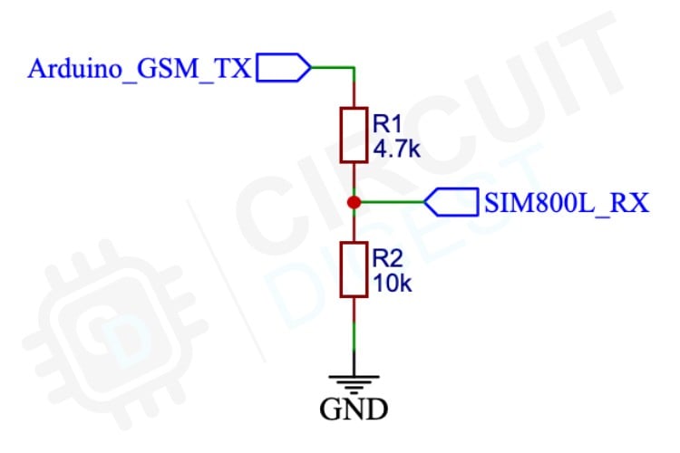
SIM800L GSM Module Connections (Requires Level Shifting)
The SIM800L module needs special attention because it operates at 3.3V logic levels while Arduino uses 5V. We need a voltage divider circuit to protect the SIM800L from damage. If you are new to the SIM800L GSM module, check out our Arduino SIM800L tutorial to understand the basics of this module and how to use it with Arduino.
Important: Power the SIM800L through a diode from Arduino's 5V pin when using a power bank for adequate current supply.
Critical Connection Notes
Power Requirements: Never power this Arduino GPS tracker from a computer USB port alone. The SIM800L requires up to 2A during transmission, which standard USB ports cannot provide. Always use a power bank or external 5V power supply.
Reset Pin Connection: Connect Arduino Pin 2 to the RST (reset) pin. This enables automatic switching between GPS and GSM modes to prevent memory corruption issues common with Arduino UNO's limited 2KB RAM.
Programming Tip: Always disconnect the GPS module's TX wire from Arduino Pin 0 before uploading code. The continuous GPS data interferes with programming. Reconnect after successful upload.
As mentioned earlier, Pin 2 connects to the Arduino's RST (reset) pin. This is used to switch between the GPS and GSM modes. If you wonder why we have to do this, it is because of the limited RAM available in the ATMEGA328. Without this, we have faced memory corruption when we used both GPS and GSM routines in the same sketch, caused by the huge string elements used in NMEA parsing and GSM HTTP post request payload. To prevent these kinds of issues, we have implemented two modes, in which the MCU will only need to handle the global and local variables that are specific to that mode, which prevents any memory corruption.
While testing the circuit, I noticed that some clone Arduino boards have issues with the software serial. In some instances, even simple serial pass-through examples didn’t work. We never had any issue with a genuine Arduino Uno board. I assume this is because the Atmega328 used in these boards is also non-genuine. So keep this in mind, and if you face such issues, try to use a genuine Arduino board. Here is the final setup of our hardware.
Arduino GPS Tracker Code Explanation
With the hardware connections complete, the next step involves implementing code for your GPS tracker. The GeoLinker Lite library simplifies the coding process by handling GPS communication, GSM connectivity, and cloud integration through straightforward function calls.
GeoLinker Lite Arduino Library
As mentioned earlier, we'll be using our GeoLinker Cloud platform for data storage and the specially designed GeoLinker Lite library optimised for Arduino UNO's limited 2KB RAM. We previously released the GeoLinker library for development boards with higher RAM capacity, such as the ESP32, ESP8266, Arduino UNO R4, Raspberry Pi Pico W, and Pico 2W. These boards can handle the full GeoLinker library without issues. Our ESP32 GPS tracker project shows how this library works and how to use it with ease.
But when it comes to the classic boards like Arduino UNO R3 and Nano, they have a limited RAM of only 2Kb, which prevents them from using the standard GeoLinker library. These classic boards remain popular for many projects, but their memory constraints require a different approach. To address this limitation, we have released GeoLinker Lite, a simplified version designed specifically for boards with limited memory.
GeoLinker Lite includes the core functions needed for GPS tracking whilst working within the memory limits of boards like Arduino UNO R3 and Nano. This library allows users of classic Arduino boards to connect to our cloud platform for location tracking and remote monitoring.
Begin by installing the GeoLinker Lite library through the Arduino IDE library manager. Open the Arduino IDE, navigate to Tools > Manage Libraries, then search for "GeoLinker Lite" in the Library Manager. Click Install to add the library to your Arduino environment.
This library is specifically optimised for Arduino UNO R3 and Nano boards with limited RAM capacity.
#include <GeoLinkerLite.h>
GeoLinkerLite geoLinker(Serial, Serial);
The code starts by including the GeoLinker Lite header file with #include <GeoLinkerLite.h>. Next, create a GeoLinkerLite instance using GeoLinkerLite geoLinker(Serial, Serial). This constructor takes two parameters: the first Serial, which refers to GPS communication, and the second Serial handles debug output. Both use the same Serial port since the Arduino Uno has only one hardware serial. Using multiple software serials can cause issues, and the GPS module only sends data to the Arduino, whilst debug information goes to the serial monitor.
void setup() {
  Serial.begin(9600);
  delay(1000);
  geoLinker.setResetPin(2);                    // Reset control pin
  geoLinker.setGSMPins(8, 9);                  // GSM RX, TX pins
The setup function initialises serial communication at a 9600 baud rate. A 1000ms delay allows the system to stabilise before configuration begins. The geoLinker.setResetPin(2) function configures digital Pin 2 as the reset control pin, enabling automatic system restart when needed. This is necessary to switch between modes since there is no software-based reboot control for Arduino. The geoLinker.setGSMPins() function assigns RX and b for communication with the SIM800L module.
  geoLinker.setModemAPN("your.apn.here");      // Your carrier's APN
  geoLinker.setAPIKey("your_api_key");         // Your GeoLinker API key
  geoLinker.setDeviceID("arduino_tracker");    // Unique device ID / Device name
After that, you can find the network and cloud configuration parameters. The geoLinker.setModemAPN() function is used to set your mobile carrier's Access Point Name, which is essential for GPRS connectivity. Replace this with your specific carrier's APN settings. The geoLinker.setDeviceID() function assigns a unique identifier to your tracker for identification on the cloud platform. By configuring the device ID, you can not only easily identify your tracker, but also use multiple such trackers in a single Circuit Digest Cloud account.
The geoLinker.setAPIKey() function is used to configure the API key that is necessary to connect your device to the GeoLinker Cloud platform. You can obtain your unique API key from your CircuitDigest Cloud account. Just go to the official CircuitDigest Cloud website at https://circuitdigest.cloud and in the top right corner, click Sign in.
If you are new to CircuitDigest Cloud, you need to register a new account by following the steps below.
Registering a New Account in Circuit Digest Cloud
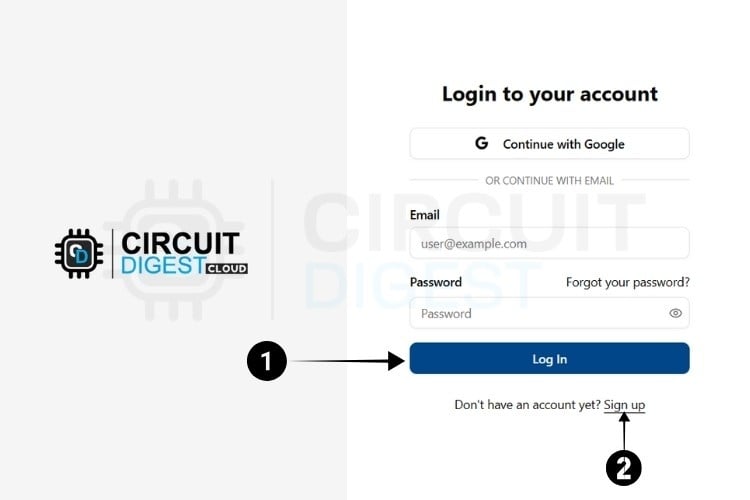
⇒ Step 1:
Visit the Circuit Digest. Cloud Home Page. Click the "Login" button located at the bottom, which redirects to the login page.
⇒ Step 2:
If you already have an account, log in using your existing credentials. If not, go to the registration page to create an account by filling in the required details. Once completed, click "Register Now" to sign up.
⇒ Step 3:
After registering, use your email ID and password to log in on the login page. Once logged in, click on "My Account" at the top right corner, where you click the API Keys from the Dropdown options.
The next step is to generate the API Key.

Generating API Key
⇒ Step 4: You will be directed to a page where you can generate your API Key.
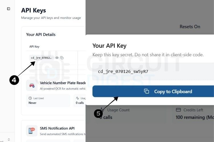
⇒ Step 5: By pressing the copy icon near the API Key, your key gets instantly copied to the clipboard.
Currently, there is a usage limit of 100 requests per API key for both the SMS and ANPR APIs and 10,000 data points for GPS tracking. Once you reach this limit, you can generate another key, which provides an additional 100 uses, which is more than enough for a hobby project or a pilot engineering project.
This usage limit is in place to prevent server overload.
With this, we are ready to move to hardware.
*Note: A 10-second rate limit applies to all API calls, allowing one request every 10 seconds.
More details on how to use GeoLinker can be found in our previous tutorial, Free IoT-based GPS Tracking Map for ESP32, NodeMCU, and Arduino.
  geoLinker.setMaxRetries(3);                  // Max retry attempts to send a data points
  geoLinker.setDebugLevel(1);                  // Debug level
  geoLinker.setTimeOffset(5, 30);              // Timezone: Eg. india +5:30 hours
The geoLinker.setMaxRetries() function determines how many times the system attempts to send data via GPRS before giving up. This helps handle temporary network issues without infinite retry loops. The geoLinker.setDebugLevel() function controls the amount of diagnostic information sent to the serial monitor. With 0, no debugging data will be printed. With 1 minimal debugging information, and 2 detailed debugging information will be printed on the serial monitor. The geoLinker.setTimeOffset(5, 30) function configures timezone settings, with the example showing India's UTC+5:30 offset. This is used for time offset correction since the time stamp from the GPS data will be UTC.
  geoLinker.begin();
  delay(1000);                              // Increase this delay to increase update interval
  geoLinker.run();
The geoLinker.begin() function initialises all components, establishes GPS communication, connects to the GSM network, and prepares the system for operation. After a 1000ms delay, the geoLinker.run() function starts the main tracking loop. This function handles GPS data collection, processes location information, and transmits data to the GeoLinker Cloud platform. Increasing the delay before geoLinker.run() extends the interval between location updates. By default, the delay between the location updates is 20 seconds.
The loop function remains empty with only a delay statement because of the geoLinker.run() function manages the entire tracking process internally. The system operates continuously within the run function, collecting GPS data, managing GSM communication, and handling automatic resets when necessary.
Download Code from GitHub Repository
Here is the link to our GitHub repository, where you'll find the source code, schematics, and all other necessary files to build your own GPS Tracker using Arduino Uno, SIM800L, and Neo-6 M GPS module.


Testing Arduino GPS Tracker in the Real World
After uploading the code, take your Arduino GPS tracker outdoors for testing. GPS modules require a clear sky view and typically need 2-5 minutes for initial satellite lock. Open Serial Monitor at 9600 baud to watch the boot sequence. You should see GPS signal acquisition, network registration, and successful data uploads to GeoLinker Cloud, as shown in the image below. You can see the serial monitor of Arduino on the left and the Geolinker map on the right. The hardware is connected to a laptop and moved around on the streets during this testing.
![]()
Next, we decided to test by moving to different locations and see how the values get updated on the geolinker map. The default tracking interval in our code is 20 seconds, and location accuracy should be within 3-5 meters. We powered the hardware with a power bank placed in on the car dashboard and started driving to test if the DIY GPS tracker is working the way it is supposed to. As you can see in the image below, as we drive around, the location gets updated on the app. You can even see that the waypoints are plotted very close together at places where there is traffic.
![]()
In conclusion, this simple Arduino Location tracker works much better than we expected it to be and is very practical to be used for vehicle tracking, pet tracking, or asset tracking applications. We build everything on a breadboard to keep it beginner-friendly friendly but you can take it ahead and build a PCB with a neat enclosure. Also, having the location data sent to GeoLinker opens to many more possibilities. You can not only visualise your data with Geolinker, but you can also share it, filter it, download it as a table, calculate speed, distance, and much more. You can fiddle around with the options there to explore more. You can track multiple devices with just a single API key, but the maximum number of waypoints is limited to 10,000, which is more than enough for personal use or for testing small prototypes. After 10,000 waypoints, your oldest data will be overwritten. You can also delete these waypoints if you want to make space for new devices.
Arduino GPS Tracker Troubleshooting Guide
Building an Arduino GPS tracker can present various challenges. This comprehensive troubleshooting guide covers the most common issues and their solutions, organised by category for quick problem resolution.
Programming and Upload Issues
⇥ Q1: Cannot upload code to Arduino - "programmer not responding" error?
Solution: The GPS module continuously sends data to Pin 0 (RX), blocking code uploads. Disconnect the GPS TX wire from Arduino Pin 0 before programming. After a successful upload, reconnect the wire. Always follow this sequence: Disconnect → Upload → Reconnect.
⇥ Q2: Code compiles, but Arduino resets continuously?
Solution: This indicates an insufficient power supply. The SIM800L requires up to 2A during transmission. Use a quality power bank (minimum 2A output) instead of computer USB power. Weak power causes brownout resets during GSM operations.
GPS Module Issues
⇥ Q3: GPS show "no data" or "waiting for GPS signal" continuously?
The NEO-6M GPS modules might be tricky to get working sometimes; always test them outdoors with a proper power supply and antenna. If you are facing a problem, you can read our NEO-6m Troubleshooting guide, in which we have discussed every possible problem and its solutions
⇥ Q4: GPS works initially, but stops after some time.
Solution: This often indicates power supply instability. The GPS module needs consistent 3.3V-5V power. Check all power connections are secure and use a stable power source. Loose connections cause intermittent GPS failures.
GSM/Cellular Connection Problems
⇥ Q5: SIM800L doesn't respond or shows network registration failed?
1. Verify the SIM card works in a phone first
2. Check the SIM card supports 2G networks (Jio doesn't work - 4G only)
3. Ensure proper voltage divider circuit (4.7kΩ + 10kΩ resistors)
4. Test with known working carriers: Airtel, Vi, BSNL
5. Verify antenna connection to SIM800L
⇥ Q6: Getting HTTP 401 errors when sending data to the cloud?
Solution: HTTP 401 indicates authentication failure. Replace the placeholder API key with your actual GeoLinker Cloud API key. Get your free API key from the Circuit Digest Cloud account. Verify the API key is correctly pasted without extra spaces.
Hardware and Connection Issues
⇥ Q7: Software serial not working with clone Arduino boards?
Solution: Many clone Arduino boards use non-genuine ATMEGA328P chips with software serial issues. Test with a simple serial passthrough example first. If problems persist, use a genuine Arduino UNO R3 board. To build this GPS tracker Arduino project, you need reliable serial communication, so get a high-quality Arduino UNO board with a DIP IC and not an SMD IC.
⇥ Q8: SIM800L get hot or stop working after some time?
Solution: Overheating indicates power supply issues. The SIM800L needs 3.7V-4.2V with high current capability. Use the diode voltage drop method from the Arduino 5V pin when powered by a power bank. Never exceed 4.2V, or the module may be damaged permanently.
Performance Optimization
⇥ Q9: How to reduce battery consumption for portable tracking?
1. Increase the delay before geoLinker.run() for less frequent updates
2. Use sleep modes between GPS readings (advanced modification)
3. Reduce debug level to 0 for production use
4. Consider solar charging for permanent outdoor installations
5. Use an efficient power bank with low self-discharge
⇥ Q10: Can I track multiple vehicles with one account?
Yes! Set unique device IDs for each Arduino GPS tracker using geoLinker.setDeviceID("tracker_1"), geoLinker.setDeviceID("tracker_2"), etc. All trackers can use the same API key and will appear separately on your GeoLinker Cloud dashboard.
Building your own Arduino GPS tracker provides complete control over your tracking data while eliminating expensive monthly subscription fees. This project demonstrates that with basic components costing $15-20, you can create a professional-grade tracking system rivalling commercial alternatives that charge $20-50 monthly.
The GeoLinker Lite library makes this GPS tracking project using Arduino accessible to beginners while providing the flexibility for advanced customisations. Whether you're tracking vehicles, assets, or personal items, this open-source approach offers unlimited scalability and modification possibilities. If you have any questions about this project, please leave them in the comment section at the bottom of this page, and we will get back to you. Would love to hear your thoughts and suggestions.
Other Projects on GPS Location Tracking
Previously, we have built many interesting Arduino projects and a few with GPS location tracking. If you want to know more about those projects, the links are given below.
DIY Location Tracker using GSM SIM800 and Arduino
Build a DIY GPS location tracker using Arduino UNO, SIM800 GSM module, and GPS sensor. Learn how to send real-time location via SMS using latitude and longitude coordinates.
Track and log live GPS coordinates to Google Maps using NodeMCU, Neo6M GPS, and ThingSpeak IoT platform. This project shows how to upload real-time GPS data over Wi-Fi and visualise location history.
Build A Low Power SMS Based Vehicle Tracking System with an A9G GSM+GPS Module and Arduino
Create a compact GPS tracker using an A9G GSM/GPS module and Arduino. This project combines both cellular connectivity and GNSS tracking in one chip, sending SMS updates with real-time location. Ideal for makers wanting a lightweight and standalone tracking solution for smart bags, vehicles, or asset monitoring.
Complete Project Code
/*
* GeoLinkerLite Library
* Tutorial Link: https://circuitdigest.com/microcontroller-projects/arduino-gps-tracker-…
*Code for: Arduino GPS Tracker Project
* Code by: Jobit, CircuitDigest
*/

#include <GeoLinkerLite.h>
// Create the GeoLinkerLite instance
// Using Serial for both debug and GPS
GeoLinkerLite geoLinker(Serial, Serial);
void setup() {
   Serial.begin(9600);
   delay(1000);

   // Configure settings (optional - defaults are set in the library)
   geoLinker.setResetPin(2);                    // Reset control pin
   geoLinker.setGSMPins(8, 9);                  // GSM RX, TX pins
   geoLinker.setModemAPN("your.apn.here");      // Your carrier's APN
   geoLinker.setAPIKey("your_api_key");         // Your GeoLinker API key
   geoLinker.setDeviceID("arduino_tracker");    // Unique device ID / Device name
   geoLinker.setMaxRetries(3);                  // Max retry attempts to send a data ponit via GPRS
   geoLinker.setDebugLevel(1);                  // Debug level
   geoLinker.setTimeOffset(5, 30);              // Timezone: Eg. india +5:30 hours

   // Initialize the library
   geoLinker.begin();

   // Run the main functionality
   delay(1000);                                // Increase this delay to increase upate interval
   geoLinker.run();
}
void loop() {
   // Should never reach here as both modes end with reset
   delay(1000);
}
Comments
I'm looking forward to the 4G version, there's no 2G, or 3G in Australia, I want to put it in my caravan. Any idea when it will be released?
Thank you!
So can id do this project except the sim800l gsm module as in many my gsm isn't working at all due to network issue or power issue maybe so, can it be done without the gsm?

In the components section, you forgot to mention the diode you used. Moreover, what tyle of diode did you use? Along with it exact number?