
This GPS tracker using ESP32 should be an exciting project, especially for beginners interested in electronics and software development. It’s a project that brings childhood curiosity about tracking everything around us to life. While the hardware setup is relatively simple, the real challenge lies in the software. But that’s no longer a concern, thanks to the introduction of the GeoLinker API.
At Circuit Digest Cloud, we’ve launched an easy-to-use, free API called GeoLinker. This API enables you to plot and route the location data sent from your device to a server, making it effortless to visualize and track positions.
In this tutorial, we’ll build a GPS tracker using a Neo-6M GPS module with ESP32, covering the hardware setup and GeoLinker as the software component. Let's dive in and get started! Explore our other GPS tracker projects, like an Arduino GPS tracker using SIM800L and Neo-6M and a Raspberry Pi Pico GPS tracker. We've built many other projects using an ESP32 that we think you'll enjoy.
GPS Tracker using ESP32 and GeoLinker API - Quick Overview
Build Time: 3-5 hours | Cost: $20-30 | Difficulty: Beginner-Intermediate
What You'll Learn: ESP32 programming, Neo-6M GPS module, GeoLinker API, UART communication
Applications: Vehicle tracking, Personal location monitoring, Asset management, Route visualization
Table of Contents
How Does the ESP32 GPS Tracker Work?
In this project, we are going to build a simple GPS tracker that combines a GPS module for ESP32 with cloud connectivity, making it easier to implement at both the hardware and software levels. For hardware, we will be using the well-known ESP32 Development Board along with the Neo-6M GPS Module. On the software side, we will utilize the GeoLinker API, developed by Circuit Digest Cloud.
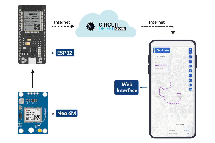
We will fetch GPS data from the Neo-6M GPS module using the ESP32 and send this data to a map plotting and routing API via a simple HTTP request. Each data point will be appended to the database. By logging into our Circuit Digest Cloud account, we can view the live plotted data along with the route tracking.
An extra feature implemented in this project is online/offline data handling. Specifically, when the internet is unavailable, the data is stored in a local variable. Once the connection is restored, the stored data is pushed to the server first, followed by the newly fetched data. This is quite an interesting and useful feature, especially in areas where internet connectivity is unreliable.
With this, let's move on to the components required for this project.
Components Required
Only a minimal number of components are required for this project. However, it is important to verify the functionality of each component before use. As always, selecting components is your choice, depending on your budget and creativity, with no limitations on customization. Below are the components we have used to build a GPS tracker using esp32.
LEDs - 2
1K Resistor - 2
BreadBoard - 1
Connecting Wires - As required
There is no specific reason for selecting the Neo-6M GPS module apart from its cost-effectiveness. If you are using the Neo-6M, as I did, and if your GPS module is not working check out the linked article for troubleshooting. You can also use any other GPS module for ESP32 to complete this project. Keeping theory Things apart let's move to the actual project, starting from software.
GeoLinker Setup for GPS Tracker
Like most CircuitDigest Cloud APIs, GeoLinker also requires an API key for authorization. Follow the steps below to receive your free API key.
Visit Circuit Digest Cloud and in the top right corner, click Sign in.
If you are new to CircuitDigest Cloud, you need to register a new account by following the steps below.
Registering a New Account in Circuit Digest Cloud
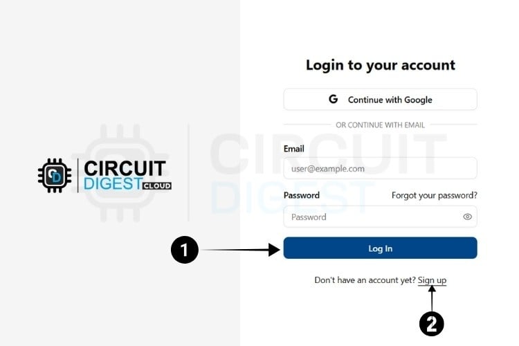
Step 1: Visit the Circuit Digest.Cloud Home Page. Click the "Login" button located at the bottom, which redirects to the login page.
Step 2: If you already have an account, log in using your existing credentials. If not, go to the registration page to create an account by filling in the required details. Once completed, click "Register Now" to sign up.
Step 3: After registering, use your email ID and password to log in on the login page. Once logged in, click on "My Account" at the top right corner, where you click the API Keys from the Dropdown options.
The next step is to generate the API Key.

Generating API Key
Step 4: You will be directed to a page where you can generate your API Key.
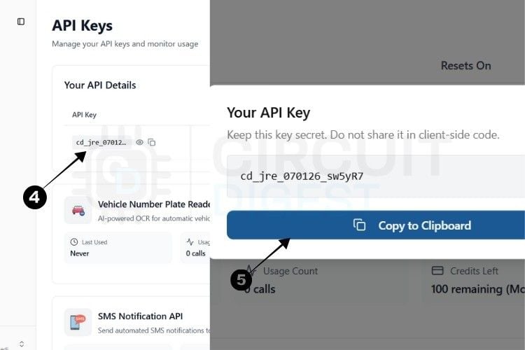
Step 5: By pressing the copy icon near the API Key, your key gets instantly copied to the clipboard.
Currently, there is a usage limit of 100 requests applies per API key for both the SMS and ANPR APIs and 10,000 data points for GPS tracking. Once you reach this limit, you can generate another key, which provides an additional 100 uses.
This usage limit is in place to prevent server overload.
With this, we are ready to move to hardware.
*Note: A 10-second rate limit applies to all API calls, allowing one request every 10 seconds.
ESP32 GPS Tracker Circuit Diagram
The circuit diagram is quite self-explanatory, as there are only a few connections, making it simple to understand. The complete circuit diagram to build a GPS tracker using ESP32 is shown below.
The ESP32 is powered via its USB port, while the GPS module receives a stable 3.3V supply from the ESP32. Communication between the two modules is established through UART, where the GPS module's TX (Transmit) pin connects to the ESP32's RX (IO16), and the GPS RX (Receive) pin connects to the ESP32's TX (IO17). If you need more help you can also check out our article on how to use NEO-6M GPS module with ESP32 and learn more.
With this, the circuit connections are complete. Below, you can see the assembly of the hardware components.
While assembling the components, carefully check for proper connections between the components and the breadboard, as improper wiring might cause unidentified issues.
Next, we can move on to the coding part.
Arduino Code
The coding part is simple and straightforward. There’s not much to work out.
Thanks to our newly launched GeoLinker Official Arduino Library, coding is made easy with all the required features. So let’s begin the explanation.
1. Libraries and Dependencies
#include <GeoLinker.h> Purpose: Main library for GPS tracking and cloud connectivity
Functionality:
Handles GPS data parsing (NMEA protocol)
Manages network communication (WiFi/GSM)
Provides cloud service integration
Handles offline data storage
Manages automatic reconnection
Repo Link: https://github.com/Circuit-Digest/GeoLinker
2. GPS Configuration
HardwareSerial gpsSerial(1);
#define GPS_RX 16
#define GPS_TX 17
#define GPS_BAUD 9600
The GPS module communication is established through a hardware serial interface using HardwareSerial gpsSerial(1), which creates a reliable serial instance using UART1.
The physical connections are defined with GPIO16 serving as the RX pin to receive data from the GPS module, while GPIO17 functions as the TX pin to send data to the GPS module.
The communication operates at a standard baud rate of 9600, which is the typical speed for NMEA GPS modules. Hardware serial is specifically chosen over software serial because it provides much more reliable communication for continuous GPS data streaming, ensuring that no critical location data is lost during transmission.
3. Wifi Configuration Variables
const char* ssid = "yourSSID";
const char* password = "yourPASSWORD";
Network connectivity is established through two simple configuration variables: ssid and password. These string constants should be replaced with your actual WiFi network credentials to enable internet connectivity for the GPS tracker.
4. GeoLinker Configuration Variables
API Authentication
const char* apiKey = "xxxxxxxxxxxx";
const char* deviceID = "ESP-32_Tracker";
Explanation:
API Key: Authenticates your device with GeoLinker cloud service
Device ID: Unique identifier to distinguish this tracker from others
Data Transmission Settings
const uint16_t updateInterval = 5;
const bool enableOfflineStorage = true;
const uint8_t offlineBufferLimit = 20; updateInterval: How often GPS data is sent to the cloud (5 seconds)
enableOfflineStorage: Boolean flag for offline data buffering
offlineBufferLimit: Maximum stored records when offline (memory management). In case of reaching the limit, old data will be replaced with newer ones. In other terms, it will store the latest (eg:20) data in the memory.
Connection Management
const bool enableAutoReconnect = true;
const int8_t timeOffsetHours = 5;
const int8_t timeOffsetMinutes = 30;
Auto-reconnect: Automatically attempts WiFi reconnection if disconnected
Timezone Offset: Adjusts timestamps to local time (example: IST = UTC+5:30)
GeoLinker Instance
GeoLinker geo;The main tracking operations are handled through a single GeoLinker geo object, which serves as the primary interface for all GPS tracking, data processing, and cloud communication functions.
5. Setup Function Explanation
Serial Initialization
Serial.begin(115200);
delay(1000);
gpsSerial.begin(GPS_BAUD, SERIAL_8N1, GPS_RX, GPS_TX);
Debug Serial: 115200 baud for fast debugging output
Delay: Ensures serial port stabilizes
GPS Serial: Configures custom pins with 8N1 format (8 data bits, no parity, 1 stop bit)
GeoLinker Configuration Sequence
geo.begin(gpsSerial);
geo.setApiKey(apiKey);
geo.setDeviceID(deviceID);
geo.setUpdateInterval_seconds(updateInterval);
geo.setDebugLevel(DEBUG_BASIC);
Initialize: Links GPS serial interface to GeoLinker
Authentication: Sets up cloud service access
Device Identity: Establishes unique device tracking
Timing: Controls how often data is sent
Debugging: Sets information output level
Advanced Settings
geo.enableOfflineStorage(enableOfflineStorage);
geo.enableAutoReconnect(enableAutoReconnect);
geo.setOfflineBufferLimit(offlineBufferLimit);
geo.setTimeOffset(timeOffsetHours, timeOffsetMinutes);
Offline Storage: Saves data when the network is unavailable
Auto-reconnect: Handles connection drops automatically
Buffer Limit: Prevents memory overflow on small MCUs
Timezone: Ensures accurate local timestamps
Network Connection
geo.setNetworkMode(GEOLINKER_WIFI);
geo.setWiFiCredentials(ssid, password);
if (!geo.connectToWiFi()) {
   Serial.println("WiFi connection failed!");
}
setNetworkMode: Chooses WiFi over GSM/cellular
setWiFiCredentials: Provides network access information
Connection: Attempts initial WiFi connection and , Reports in case of connection failures
6. Loop Function Explanation
Main Processing Cycle
uint8_t status = geo.loop();The heart of the GPS tracking system operates through the geo.loop() function, which executes a comprehensive processing cycle during each iteration. This function continuously reads NMEA sentences from the GPS module, parsing the raw data to extract coordinates, timestamp information, and satellite quality metrics.
The system validates the GPS fix quality to ensure location accuracy before proceeding with data transmission. Network connectivity is continuously monitored to maintain reliable communication with the cloud service.
When connectivity is available, location data is transmitted to the cloud service in real-time. During network outages, the offline management system stores data locally for later transmission. Throughout all operations, comprehensive error recovery mechanisms handle various failure scenarios to maintain system reliability.
Status Code Processing
if (status > 0) {
   Serial.print("[STATUS] GeoLinker Operation: ");

   // Interpret status codes and provide user feedback
   switch(status) {
     case STATUS_SENT:
       Serial.println("✓ Data transmitted successfully to cloud!");
       break;

     case STATUS_GPS_ERROR:
       Serial.println("✗ GPS module connection error - Check wiring!");
       break;

     case STATUS_NETWORK_ERROR:
       Serial.println("⚠ Network connectivity issue - Data buffered offline");
       break;

     case STATUS_BAD_REQUEST_ERROR:
       Serial.println("✗ Server rejected request - Check API key and data format");
       break;

     case STATUS_PARSE_ERROR:
       Serial.println("✗ GPS data parsing error - Invalid NMEA format");
       break;

     case STATUS_INTERNAL_SERVER_ERROR:
       Serial.println("✗ GeoLinker server internal error - Try again later");
       break;

     default:
       Serial.print("? Unknown status code: ");
       Serial.println(status);
       break;
   }
 }
Success Codes
STATUS_SENT: Data successfully transmitted to cloud
GPS-Related Errors
STATUS_GPS_ERROR: GPS module communication failure
STATUS_PARSE_ERROR: Invalid NMEA data format
Network-Related Errors
STATUS_NETWORK_ERROR: WiFi/internet connectivity issues
STATUS_BAD_REQUEST_ERROR: Server rejected data (authentication/format)
STATUS_INTERNAL_SERVER_ERROR: Cloud service problems
With this, the code explanation is complete. The whole code is available at the bottom of this article. Now, the only pending task is uploading it to the ESP32, and the magic happens.
ESP32 GPS Tracker - Demo and Testing
After successfully uploading the code, the system should start working.
In this project, the idea is simple:
GPS data is collected and sent to the server. If the internet is unavailable, the data is stored locally and uploaded once the connection is restored.
That’s exactly what we tested during our trial.
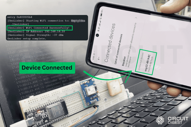
For the network connection, I used a mobile hotspot. Once I powered the system using the PC's USB port, I turned on the Wi-Fi hotspot on the mobile, and the ESP32 connected instantly.
After ensuring that everything was working fine, we began our short journey from the office. A slight movement was observed on the map.
For testing, the system was set to push data every 2 seconds.
Note: For real-world usage, a delay between 15 to 60 seconds is ideal.
Once everything was running smoothly, we decided to test the offline storage feature.
To do this, I turned off the mobile hotspot for 1 minute, forcing the device into offline mode.
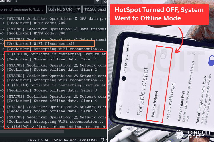
During the offline period, the data was stored in the buffer without any loss.
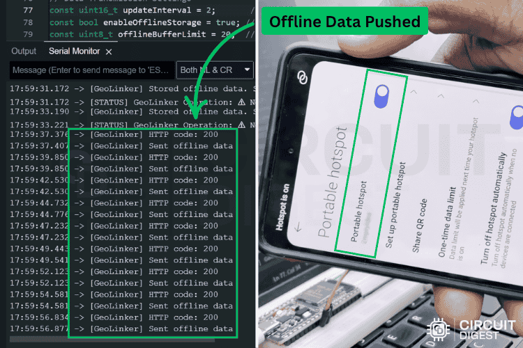
Once the internet was restored, the buffered data points were pushed instantly one after the other, and the system returned to online mode.
After 20 minutes, we completed our test and returned to the office.
We have successfully demonstrated and verified the working of the GPS tracker and its application.
With future updates in GeoLinker, using it as a generic GPS plotting and routing platform will become even more seamless
GitHub Repository with Code and Circuit
The complete code for this GPS Tracker using ESP32 project is provided at the bottom of this page. Additionally, you can find the source code in our GitHub repository linked below.


Related ESP32 GPS Tracker Projects for Data Visualization
Previously, we have used GPS trackers in various projects to collect and visualize location data. If you want to explore these projects, check out the links below.
GPS Visualizer to Upload Data and Visualize GPS Maps for Arduino, ESP32 & other Embedded Devices
This tutorial introduces the CircuitDigest Cloud GeoLinker API, a free tool designed to simplify GPS data handling. It allows users to upload GPS data from devices like Arduino, ESP32, NodeMCU, and Raspberry Pi, and visualize the data on a map with routes and timestamps.
In this project, a NodeMCU, NEO-6M GPS module, and OLED display are integrated to create a GPS location tracker. The system sets up a local web server to display location details, including a direct link to view the location on Google Maps.
Lora-Based GPS Tracker using Arduino and LoRa Shield
This project demonstrates building a GPS tracking system using LoRa technology for long-range communication. A transmitter reads location data from a NEO-6M GPS module and transmits it wirelessly over LoRa, making it suitable for applications requiring extended range and low power consumption.

How to Use GPS module with STM32F103C8 to Get Location Coordinates
This tutorial covers interfacing a GPS module with an STM32F103C8 microcontroller to retrieve location coordinates. The project includes displaying the coordinates on a 16x2 LCD and provides guidance on programming the STM32 for GPS data acquisition.
DIY Location Tracker using GSM SIM800 and Arduino
This project involves creating a location tracker using an Arduino and a SIM800 GSM module. The system receives calls from users, retrieves GPS coordinates, and sends the location data back via SMS, allowing real-time tracking without the need for internet connectivity.
Complete Project Code
/*
* ===============================================================
*                    GEOLINKER GPS TRACKER
* ===============================================================
*
* FEATURES:
* - Real-time GPS tracking with NMEA data parsing
* - WiFi connectivity for data transmission
* - Offline data storage with configurable buffer limits
* - Automatic reconnection capabilities
* - Timezone offset configuration
* - Multiple debug levels for troubleshooting
* - Status monitoring with detailed error codes
* - Configurable update intervals
*
* WORKING:
* 1. Initializes GPS module on Serial1 with custom RX/TX pins
* 2. Connects to WiFi network using provided credentials
* 3. Continuously reads GPS data in main loop
* 4. Processes and validates GPS coordinates
* 5. Transmits location data to GeoLinker cloud service
* 6. Stores data offline when network is unavailable
* 7. Provides real-time status feedback via serial monitor
*
* HARDWARE REQUIREMENTS:
* - ESP32 development board
* - GPS module (NMEA compatible)
* - WiFi network access
*
* PIN CONNECTIONS:
* - GPS RX: GPIO16
* - GPS TX: GPIO17
*
* CREDITS:
* - GeoLinker Library: GPS tracking and cloud connectivity
* - ESP32 Arduino Core: Hardware abstraction layer
* - NMEA GPS Protocol: Location data standardization
*
* Author: CircuitDigest/Rithik_Krisna_M
* Version: 1.0
* Last Modified: 28/06/2025
*
* ===============================================================
*/
#include <GeoLinker.h>
// ==================================================================
//                    HARDWARE CONFIGURATION
// ==================================================================
// GPS Serial Communication Setup
HardwareSerial gpsSerial(1);  // Using Serial1 for GPS communication
#define GPS_RX 16             // GPIO16 connected to GPS module TX pin
#define GPS_TX 17             // GPIO17 connected to GPS module RX pin
// GPS Communication Settings
#define GPS_BAUD 9600         // Standard NMEA GPS baud rate (9600 bps)
// ==================================================================
//                    NETWORK CONFIGURATION
// ==================================================================
// WiFi Network Credentials
const char* ssid = "yourSSID";       // Your WiFi network name (SSID)
const char* password = "yourPassword";   // Your WiFi network password
// ==================================================================
//                   GEOLINKER CONFIGURATION
// ==================================================================
// API Authentication
const char* apiKey = "xxxxxxxxxxxx";    // Your unique GeoLinker API key
const char* deviceID = "ESP-32_Tracker"; // Unique identifier for this device
// Data Transmission Settings
const uint16_t updateInterval = 2;       // How often to send data (seconds)
const bool enableOfflineStorage = true; // Store data when offline
const uint8_t offlineBufferLimit = 20;  // Maximum offline records to store
                                       // Keep minimal for MCUs with limited RAM
// Connection Management
const bool enableAutoReconnect = true;  // Automatically reconnect to WiFi
                                       // Note: Only applies to WiFi, ignored with GSM
// Timezone Configuration
const int8_t timeOffsetHours = 5;       // Timezone hours offset from UTC
const int8_t timeOffsetMinutes = 30;    // Timezone minutes offset from UTC
                                      // Example: IST = UTC+5:30
// Create GeoLinker instance
GeoLinker geo;
// ==================================================================
//                    INITIALIZATION SETUP
// ==================================================================
void setup() {
 // Initialize serial communication for debugging
 Serial.begin(115200);
 delay(1000);  // Allow serial to initialize

 Serial.println("Starting GeoLinker GPS Tracker...");
 // Initialize GPS serial communication with custom pins
 gpsSerial.begin(GPS_BAUD, SERIAL_8N1, GPS_RX, GPS_TX);
 Serial.println("GPS Serial initialized on pins 16(RX) and 17(TX)");
 // ==================================================================
 //                   GEOLINKER LIBRARY SETUP
 // ==================================================================

 // Initialize GeoLinker with GPS serial interface
 geo.begin(gpsSerial);
 Serial.println("GeoLinker library initialized");

 // Configure API authentication
 geo.setApiKey(apiKey);
 Serial.println("API key configured");

 // Set unique device identifier
 geo.setDeviceID(deviceID);
 Serial.println("Device ID set");

 // Configure data transmission interval
 geo.setUpdateInterval_seconds(updateInterval);
 Serial.print("Update interval set to ");
 Serial.print(updateInterval);
 Serial.println(" seconds");

 // Set debug verbosity level
 // Options: DEBUG_NONE, DEBUG_BASIC, DEBUG_VERBOSE
 geo.setDebugLevel(DEBUG_BASIC);
 Serial.println("Debug level set to BASIC");

 // Enable offline data storage capability
 geo.enableOfflineStorage(enableOfflineStorage);
 if(enableOfflineStorage) {
   Serial.println("Offline storage enabled");
 }

 // Enable automatic WiFi reconnection
 geo.enableAutoReconnect(enableAutoReconnect);
 if(enableAutoReconnect) {
   Serial.println("Auto-reconnect enabled");
 }

 // Set maximum offline buffer size (important for memory management)
 geo.setOfflineBufferLimit(offlineBufferLimit);
 Serial.print("Offline buffer limit set to ");
 Serial.print(offlineBufferLimit);
 Serial.println(" records");

 // Configure timezone offset for accurate timestamps
 geo.setTimeOffset(timeOffsetHours, timeOffsetMinutes);
 Serial.print("Timezone offset set to UTC+");
 Serial.print(timeOffsetHours);
 Serial.print(":");
 Serial.println(timeOffsetMinutes);
 // ==================================================================
 //                    NETWORK CONNECTION SETUP
 // ==================================================================

 // Configure for WiFi mode (alternative: GEOLINKER_GSM for cellular)
 geo.setNetworkMode(GEOLINKER_WIFI);
 Serial.println("Network mode set to WiFi");

 // Set WiFi network credentials
 geo.setWiFiCredentials(ssid, password);
 Serial.println("WiFi credentials configured");

 // Attempt WiFi connection
 Serial.print("Connecting to WiFi network: ");
 Serial.println(ssid);

 if (!geo.connectToWiFi()) {
   Serial.println("ERROR: WiFi connection failed!");
   Serial.println("Device will continue with offline storage mode");
 } else {
   Serial.println("WiFi connected successfully!");
 }
 Serial.println("\n" + String("=").substring(0,50));
 Serial.println("GeoLinker GPS Tracker setup complete!");
 Serial.println("Starting main tracking loop...");
 Serial.println(String("=").substring(0,50) + "\n");
}
// ==================================================================
//                   MAIN PROGRAM LOOP
// ==================================================================
void loop() {
 // ==========================================
 //         GEOLINKER MAIN OPERATION
 // ==========================================

 // Execute main GeoLinker processing cycle
 // This function handles:
 // - GPS data reading and parsing
 // - Network connectivity checking
 // - Data transmission to cloud service
 // - Offline storage management
 // - Error handling and recovery
 uint8_t status = geo.loop();

 // Process and display status information
 if (status > 0) {
   Serial.print("[STATUS] GeoLinker Operation: ");

   // Interpret status codes and provide user feedback
   switch(status) {
     case STATUS_SENT:
       Serial.println("✓ Data transmitted successfully to cloud!");
       break;

     case STATUS_GPS_ERROR:
       Serial.println("✗ GPS module connection error - Check wiring!");
       break;

     case STATUS_NETWORK_ERROR:
       Serial.println("⚠ Network connectivity issue - Data buffered offline");
       break;

     case STATUS_BAD_REQUEST_ERROR:
       Serial.println("✗ Server rejected request - Check API key and data format");
       break;

     case STATUS_PARSE_ERROR:
       Serial.println("✗ GPS data parsing error - Invalid NMEA format");
       break;

     case STATUS_INTERNAL_SERVER_ERROR:
       Serial.println("✗ GeoLinker server internal error - Try again later");
       break;

     default:
       Serial.print("? Unknown status code: ");
       Serial.println(status);
       break;
   }
 }

 // Small delay to prevent overwhelming the serial output
 // The actual timing is controlled by GeoLinker's internal mechanisms
 delay(100);
}
Comments
As long as the GPS module uses standard NEMA protocol it is supported. Also make sure you are testing it some where the module can get a GPS lock. And the library is open source and available on GitHub.
=
[STATUS] GeoLinker Operation: ✗ GPS data parsing error - Invalid NMEA format
[STATUS] GeoLinker Operation: ✗ GPS data parsing error - Invalid NMEA format
[STATUS] GeoLinker Operation: ✗ GPS data parsing error - Invalid NMEA format
[STATUS] GeoLinker Operation: ✗ GPS data parsing error - Invalid NMEA format
[STATUS] GeoLinker Operation: ✗ GPS data parsing error - Invalid NMEA format
is it possible to add a micro sd module to store all the datas of a day and then upload it when logger is connected to home wifi?

One other boolshit. You must use TinyGPS++ library.
This code is not working with normal fastr new GPS ATGM336H, and no possible to change code becouse he use this starnge library instead of relable TinyGPS...