
If you are an embedded engineer and working in the electronic industry, there may come a situation where you need to determine the position of a moving object or you need to determine the altitude and velocity of a certain location. In this type of situation, a GPS module can come in very handy, so in this article, we decided to interface the NEO-6M GPS GSM module with ESP32. We will also let you know all the pros and cons of this device, so without further ado let's get right into it.
NEO-6M GPS Module Pinout
The NEO-6M GPS module has four pins: GND, TxD, RxD, and VCC. The TxD and RxD pins are used to communicate with the microcontroller.
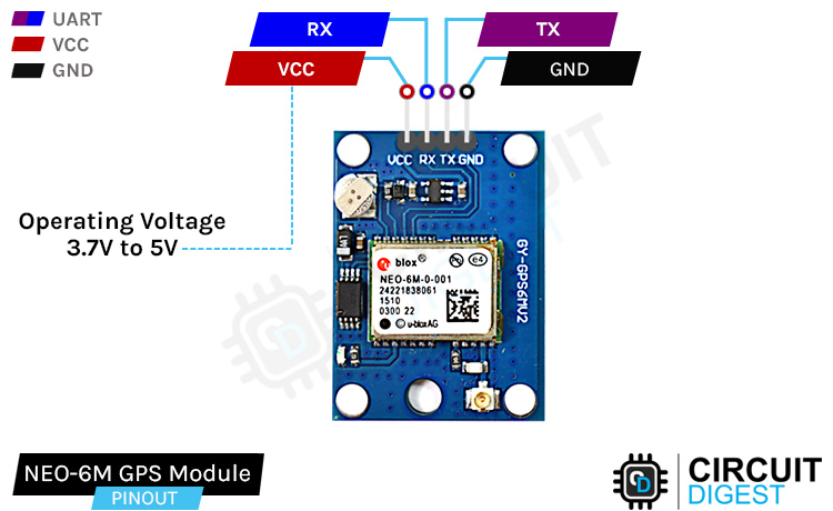
GND is the ground pin of the GPS Module and it should be connected to the ground pin of the ESP32.
TXD is the transmit pin of the GPS module that needs to connect to the RX pin of the ESP32.
RXD is the receive pin of the GPS module that needs to connect to the TX pin of the ESP32.
VCC is the power pin of the GPS module and needs to connect to the 3.3V pin of the ESP32.
NEO-6M GPS Module – Parts
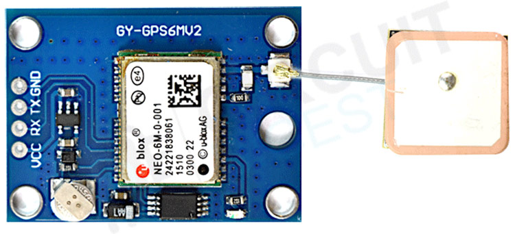
The NEO-6M module is a ready-to-use GSM module that can be used in many different applications. The parts on the NEO-6M GPS module are shown below-
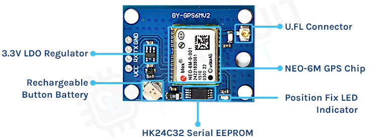
The NEO-6M GPS module has five major parts on the board, the first major part is the NEO-6M GPS chip in the heart of the PCB. Next, we have a rechargeable battery and a serial EEPROM module. An EEPROM together with a battery helps retain the clock data, latest position data(GNSS orbit data), and module configuration but it’s not meant for permanent data storage. Without the battery, the GPS always cold-starts so the initial GPS lock takes more time. The battery is automatically charged when power is applied and maintains data for up to two weeks without power. Next, we have our LDO, because of the onboard LDO, the module can be powered from a 5V supply. Finally, we have our UFL connector where we need to connect an external antenna for the GPS to properly work.
Overview of the NEO-6M GPS Module
The Global Positioning System (GPS) is a system consisting of 31 satellites orbiting earth. We can know their exact location because they are constantly transmitting position information with time through radio signals. At the heart of the breakout board, there is the NEO-6M GPS module that is designed and developed by u-blox. This is very small but it packs a lot of features. It can track up to 22 satellites over 50 channels while consuming only 45mA of current and has an operating voltage of 2.7V ~ 3.6V. One of the most interesting features of this module is its power-saving mode. This allows a reduction in system power consumption. With power-saving mode on, the current consumption of the module reduces to 11MA only. For more details about the NEO-6M GPS Module, you can check out the NEO-6M Module datasheet.
Position Fix LED Indicator:
If you take a close look at the NEO-6M GPS module board, you can find a small LED that is used to indicate that the GPS module is able to communicate with the satellites.
No blinking – it is searching for satellites.
Blink every 1s – Position Fix is found (the module can see enough satellites).
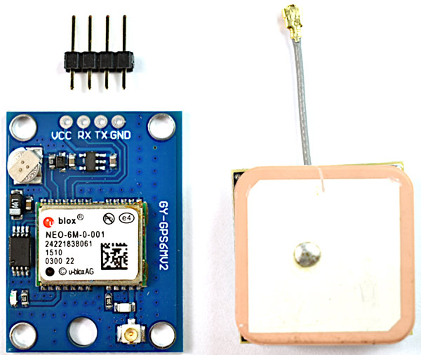
Antenna:
The module comes with a -161 dBm sensitive patch antenna that can receive radio signals from GPS satellites. You can connect the antenna to a small UFL connector which we have mentioned in the parts marking section of this article.
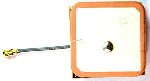
For most outdoor applications, the patch antenna will work just fine but for more demanding or indoor applications it is advised to use a 3V active GPS antenna.
Commonly Asked Questions about NEO-6M GPS Module
Q. How accurate is NEO-6M?
According to the datasheet, the NEO-6M device has 2.5m GPS Horizontal Position Accuracy in ideal conditions.
Q. How do I know if a GPS module is working?
Connect power and a UART converter with the NEO-6M GPS module, and set the baud rate to 9600. If everything is working correctly then you should get data out of the module every second.
Q. What is a GPS antenna?
A GNSS or GPS antenna is a device designed to receive and amplify the radio signals transmitted on specific frequencies by GNSS satellites and convert them to an electronic signal for use by a GNSS or GPS receiver.
Q. Why are 4 satellites needed for GPS?
The magic number is 4 because of the way that GPS calculates your exact position. Each satellite sends out a signal that includes 1) the exact time that the signal is sent and 2) the exact position of the satellite relative to the center of the Earth.
Q. What frequencies does GPS use?
All GPS satellites broadcast on at least two carrier frequencies: L1, at 1575.42 MHz, and L2, at 1227.6 MHz (newer satellites also broadcast on L5 at 1176 MHz).
Circuit Diagram for NEO-6M GSM Module
The circuit for the NEO-6M GPS module is very simple and easy to understand. In this module, all the major work is handled by the GPS module and we need two or three more components to make the GPS module work. The complete Schematic of the NEO-6M GPS Module is shown below.

In the schematic, we have a 3.3V voltage regulator that is responsible for converting the input from 5V to 3.3V and we also have an AT24C33 EEPROM and a battery. EEPROM and Battery together help in retaining battery-backed RAM that can hold clock data and position for a limited period of time. Other than that, we have the UFL connector in which you need to connect an External Patch Antenna to make the module work properly.
ESP32 NEO-6M GPS Module Circuit Diagram
Now that we have a complete understanding of the NEO-6M GPS module, we can connect all the required wires to the ESP32 board and check if the module is working properly or is it giving errors. Next, we will write some code and decode the received GPS data. The connection diagram of the NEO-6M GPS module with ESP32 is shown below.

Understanding NMEA Sentences
If we connect the module to a USB to UART converter and open up a serial monitor window, we can see some data coming out of the NEO-6M GPS module. These are called NMEA sentences, NMEA is an acronym for National Marine Electronics Association. This is a standard message format for almost all GPS receivers. A screenshot of the serial monitor window is shown below.
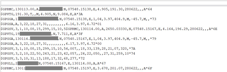
NMEA sentences start with the $ character, and each data field is separated by a comma.
There are many different types of NMEA sentences. These different types are differentiated by the first character before the first comma. The GP after the $ symbol indicates that it's a GPS position data. The $GPGGA is a basic NEMA message that provides 3D location data.
$GPGGA, 130113.00, 37XX.XXXX,N, 07XXX.XXXX, E,1,04,3.97,404.9,M,45.7,M,,*79
130113 - represents the time when data is taken, 13:01:13 UTC
37XX.XXXX,N - Latitude 37 deg XX.XXXX’ N
07XXX.XXXX,E - Longitude 007 deg 07XXX.XXXX,E
1 - fix quality (0 = invalid; 1= GPS fix. 2 = DGPS fix; 3 = PPS fix; 4 = Real Time Kinematic; 5 = Float RTK; 6 = estimated (dead reckoning); 7 = Manual input mode; 8 = Simulation mode)
04 – number of satellites being tracked
3.97 – Horizontal dilution of position
404.9, M – Altitude, in meters above the sea level
45.7, M – Height of geoid (mean sea level) above WGS84 ellipsoid
Empty - DGPS update time
Empty - DGPS station ID
*79 – the checksum data, always begins with *
There are many different NMEA sentences. If you want to know more details about them, you can check out the GIDS website which lists all the basic information.
Code for Interfacing NEO-6M GPS with ESP32
If you hook up the module with the serial monitor you will get the output on the serial monitor window that we have mentioned above. You can work with this type of data if you want to, but the easiest way is you can use a library to parse all the GPS data and store it in variables for later use. And for the code, we will do exactly that. We are going to use the TinyGPSPlus-ESP32 Library by Mike Hart. You can download the library from GitHub or you can use the Library manager of the Arduino to install the library.
Now as all the preparation is done we can move on to the code portion for ESP32, at first we start by including all the required libraries. And as the example is very basic so we are using only one library.
#include <TinyGPSPlus.h>
Next, we create a TinyGPSPlus object so that we can work with the library.
TinyGPSPlus gps;
Next, we have our setup function. In the setup function, we initialize the Serial and Serial2 of the ESP32 module so we can communicate with both the PC and the GPS module.
void setup() {
  Serial.begin(9600);
  Serial2.begin(9600);
  delay(3000);
}
Next we have our updateSerial() function. This function is a loopback between the UART1 and UART2 so that we can monitor the incoming data out of the serial monitor window.
void updateSerial(){
  delay(500);
  while (Serial.available())  {
    Serial2.write(Serial.read());//Forward what Serial received to Software Serial Port
  }
  while (Serial2.available())  {
    Serial.write(Serial2.read());//Forward what Software Serial received to Serial Port
  }
}
Next, we have the displayInfo() function, in this function, we parse the GPS Latitude and Longitude with the help of gps.location.lat() and gps.location.lng() methods of the TinyGPSPlus library and print those in the serial monitor window.
void displayInfo()
{
  Serial.print(F("Location: "));
  if (gps.location.isValid()){
    Serial.print(gps.location.lat(), 6);
    Serial.print(F(","));
    Serial.print(gps.location.lng(), 6);
  }
  else
  {
    Serial.print(F("INVALID"));
  }
}
Finally, we have our loop function, in the loop function we have first called the updateSerial() function, and comment it out, you can uncomment this if you are running the device for the first time or you are debugging the GPS module. Next, we check if serial2 is available or not. If serial2 is available, we call the displayInfo() function, this function in returns gives us the lat and long data.
void loop() {
  //updateSerial();
  while (Serial2.available() > 0)
    if (gps.encode(Serial2.read()))
      displayInfo();
  if (millis() > 5000 && gps.charsProcessed() < 10)
  {
    Serial.println(F("No GPS detected: check wiring."));
    while (true);
  }
}
This marked the end of our coding portion and we can move on to the next portion of the article.
Working of the NEO-6M GPS Module
The gif below shows how the NEO-6M GPS module works. We have written the code so that after the ESP32 is initialized, it checks if the module is working and gives the output in the serial monitor windows. Once every checking procedure is completed, the module checks if data is available and prints it in the serial monitor window.
Debugging the NEO-6M GPS Module
While working with the NEO-6M GPS module, we faced a number of issues, in this section of the article we will discuss some of those issues.
As we are using a ESP32 to communicate with the GPS module, my initial thought was to power it with the 3.3V rail of the ESP but the module was not wired and I had to connect an external battery to work with the module.
The second big issue was with the antenna. If you are thinking about using the module in indoor conditions, let me tell you it will not work because the antenna is very poor and cannot receive the satellite in indoor conditions.
If you are completely new to GPS module and facing problems in getting this module to work check out the Neo 6M GPs module not working troubleshooting guide article to check out the common problems with this module and how to solve them.
Supporting Files


Complete Project Code
#include <TinyGPSPlus.h>
// The TinyGPSPlus object
TinyGPSPlus gps;
void setup() {
  Serial.begin(9600);
  Serial2.begin(9600);
  delay(3000);
}
void loop() {
  //updateSerial();
  while (Serial2.available() > 0)
    if (gps.encode(Serial2.read()))
      displayInfo();
  if (millis() > 5000 && gps.charsProcessed() < 10)
  {
    Serial.println(F("No GPS detected: check wiring."));
    while (true);
  }
}
void displayInfo()
{
  Serial.print(F("Location: "));
  if (gps.location.isValid()){
    Serial.print("Lat: ");
    Serial.print(gps.location.lat(), 6);
    Serial.print(F(","));
    Serial.print("Lng: ");
    Serial.print(gps.location.lng(), 6);
    Serial.println();
  }
  else
  {
    Serial.print(F("INVALID"));
  }
}
void updateSerial()
{
  delay(500);
  while (Serial.available())
  {
    Serial2.write(Serial.read());//Forward what Serial received to Software Serial Port
  }
  while (Serial2.available())
  {
    Serial.write(Serial2.read());//Forward what Software Serial received to Serial Port
  }
}

My esp32 is an ESP32-WROOM-32 and it doesn't have a RX2 or TX2, just has RX0 and TX0. I also have to disconnect the GPS module to get the code to upload to the ESP.. When I apply power to the GPS module, should I not get an LED lighting up?