
Self-driving cars and connected vehicles, is sure to change the way we commute in the future. Today companies like Tesla are encouraging its owners to lend out their cars as robot taxis when not used, recently its CEO Elon Musk took it to twitter to state that there will be more than 1 million robot taxis on road by 2020. This will not only impact general transportation but also change the way how logistics operate today.
With driver-less cars carrying passengers and Trucks carrying valuable cargo, it brings in the need for a Fleet Management system in which we need to track them to know their location and ensure if they are at the right place at the right time. Generally a GPS Module is used for any sort of location tracking but here in this tutorial we will use GSM SIM800 module to build a simple Location tracking system with Arduino. This GPRS tracking system compromises the GSM modem and the microcontroller (Arduino) and is fabricated on a PCB from PCBGOGO. It works in such a way that when a phone call is made to the GSM module, the module will check the location and sends it back as a text message with Google map link to the number from which the phone call is made. This link when opened on phone will pin the location of modem on Google Maps. Sounds Interesting enough!!? So, let’s get started.
Arduino GSM Based Car Tracker Circuit Diagram
![]()
Further below I will split this circuit diagram into blocks and explain them to make sure you can use them or modify them according to your application needs.
LM2596 Power module
We have used the LM2596 Buck regulator IC to provide 4V to the SIM800 module from the input 12V. The SIM800 module requires around 2A peak current when initialized and searching for network, hence the power supply should be able to source that current, else the module will enter shutdown mode, and hence the LM2596 IC is selected which can supply upto 3A. The power supply regulator circuit is shown below.
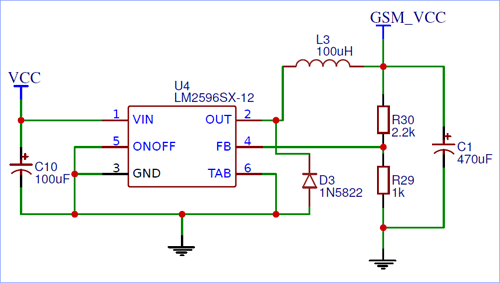
The 12V unregulated voltage is provided to pin 1 and the regulated voltage is obtained on pin 2, which is then passed through an LC filter of value 100uH and 470uF respectively to filter output switching noise. The output voltage can be set by using the resistors R30 and R29 forming the potential divider circuit and connected to feedback pin as shown above. The formulae to calculate the output voltage for LM2596 is given below
Vout = 1.23 * ((R1+R2)/R1)
In our case for the above diagram, R29 is R1 and R30 is R2. So I have selected a value of 1k for R29 and 2.2k for R30 to get an output voltage of 4V. Note that the SIM800 module reacquires voltage between 3.7V to 4.2V to operate normally.
Powering and Communicating with SIM800 IC
The SIM800 GSM modem is commonly available as modem, but we have used the bare IC package to reduce board space and cost. Using the SIM800 modem is pretty much straight forward, we simply have to power the IC though the VBAT and GND pins and then use the PWR KEY pin to enable the modem by pulling the pin down for 1 second. By default the pin is pulled high internally to VBAT through a resistor.
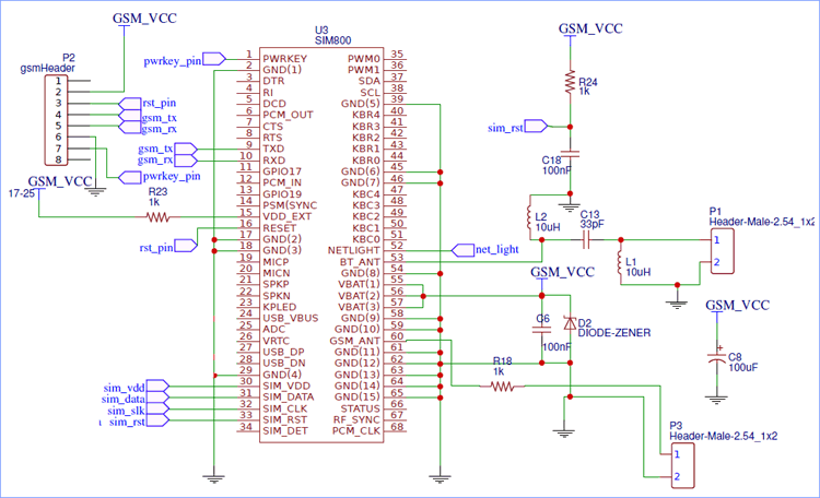
The voltage for VBAT comes from the regulated voltage (GSM_VCC) of LM2596 IC. The pin is named VBAT because it is normally power by a Lithium Battery, so if you are using it on portable devices then you can skip the LM2596 circuit and connect it directly to a lithium polymer battery. Then we have the network pins connected to a 6-pin SIM card colder to connect with our SIM card. The NETLIGHT pin is connected to a LED, this LED will act as a status LED to indicate the network status, though it is optional. Similarly the BT_ANT pin can be used to connect the module to an antenna to find network connection easily, which is again optional.
Finally we have the TxD and RxD pins pulled out to a header pin, these two pins will be used to communicate with a microcontroller like Arduino through the standard USART protocol at 9600 baud rate. The other connections shown in the circuit above is optional and does not hood any significant importance for this project.
Microcontroller Side of GSM Locator
On the Microcontroller side we have the ATMEGA328P chip form AVR, which is the one used in Arduino UNO/Nano, but here the controller is embedded directly on the board to communicate with the SIM800 module. Since the SIM800 module operates in 3.3V logic, I decided to operate the ATmega328 chip also with 3.3V itself since it also supports both 3.3V and 5V operating voltages.
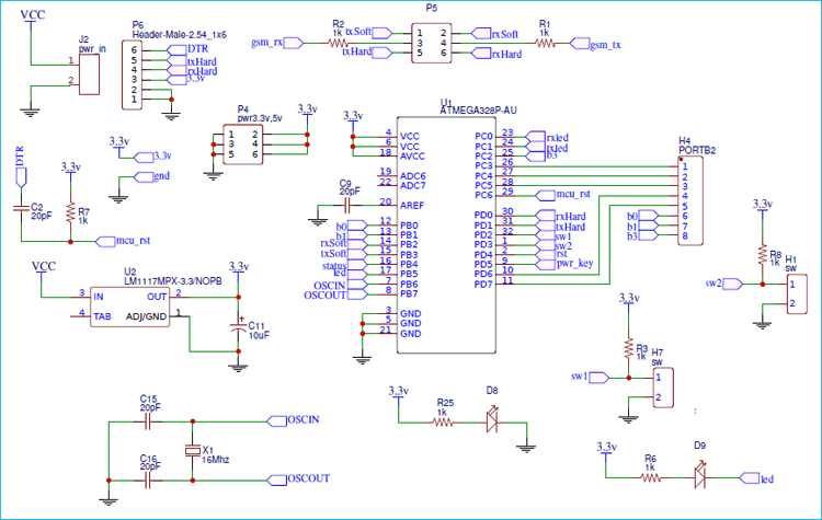
So as shown above I have used the AMS1117 3.3V regulator IC to regulate 3.3V form the input 12V and use it to power the Atmega328 IC. Although the SIM800 works on 3.3V logic level, it can also communicate with Arduino Nano/Uno externally without the need of any logic level converters. The circuit also pulls out some pins through headers to help us program the Atmega328 IC using an external FTDI programmer similar to what we do with Arduino Pro mini in 3.3V mode.
Fabricating PCB for GSM Location Tracker
Now that we have a circuit that combines the GSM module with a microcontroller we have to fabricate it on a PCB. Again to save board space I decided to use a double side board with SMD components, so I opened my PCB designing software and assigned the packages and the components used in above circuit and began designing my PCB. Once the Design was complete it looked something like this.
![]()
You can also download the design files in GERBER format and fabricate it to get your boards. The Gerber file link is given below
Download Gerber file for Arduino GSM Location tracker
Now, that our Design is ready it is time to get them fabricated. To get the PCB done is quite easy, simply follow the steps below
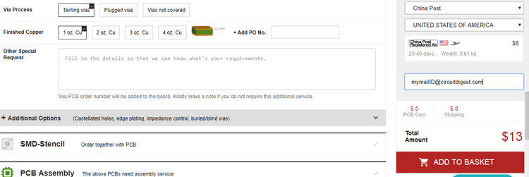
Step 1: Get into www.pcbgogo.com, sign up if this is your first time. Then, in the PCB Prototype tab enter the dimensions of your PCB, the number of layers and the number of PCB you require. Assuming the PCB is 80cm×80cm you can set the dimensions as shown below.
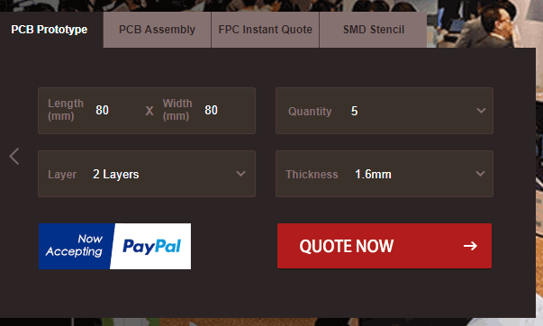
Step 2: Proceed by clicking on the Quote Now button. You will be taken to a page where to set few additional parameters if required like the material used track spacing etc. But mostly the default values will work fine. The only thing that we have to consider here is the price and time. As you can see the Build Time is only 2-3 days and it just costs only $5 for our PSB. You can then select a preferred shipping method based on your requirement.
Step 3: The final step is to upload the Gerber file and proceed with the payment. To make sure the process is smooth PCBGOGO verifies if your Gerber file is valid before proceeding with the payment. This way you can sure that your PCB is fabrication friendly and will reach you as committed.
Assembling the PCB
After the board was ordered, it reached me after some days though courier in a neatly labeled well packed box and like always the quality of the PCB was awesome. I turned on my soldering rod and started assembling the Board. Since the Footprints, pads, vias and silkscreen are perfectly of the right shape and size I had no problem assembling the board. For example the SMD pads of my 68 pin SIM800 module were of great quality and looked perfect like shown below after soldering the SIM800.
![]()
I proceeded with soldering the other components and the board was ready in just 40 minutes from the time of unpacking the box. Few pictures of the board after soldering are shown below.
![]()
![]()
As you can see I have not used the microcontroller side of the board as it is still in testing stage, so for this tutorial I will hook up the GSM module with an external Arduino nano through the header pins. I will provide an update once the microcontrller part is also tested.
Connecting the Board to Arduino Nano
The external header on the board labeled as P2 can be connected to the Arduino Nano directly. Here I have connected the pins according to the table below
Arduino Nano | SIM800 |
Pin D12 | PWR_KY |
Pin D11 | TxD |
Pin D10 | RxD |
Gnd | GND |
The power key connected to pin D12 is used to enable/disabling the module after power up, this helps in saving power when the module is not used. Pin D11 and D12 is connected to Tx and Rx pins respectively, we will program the Arduino to used these pins as software serial to communicate with the board. The set-up looks like this below once the connections are made.
![]()
Programming Arduino for GPRS Vehicle Tracking System
The complete project can be split into three major sections, such as receiving the call from the user, getting the GPS co-ordinates from SIM800, sending the GPS data to caller via SMS. Since we have already learnt how to send SMS using GSM module and Arduino and handle calls with GSM module we will not discuss much about that in this article.
Obtaining geo-coordinates locations (Latitude and Longitude) from SIM800 GSM module:
Obtaining GPS coordinate from GPS is easy compared to GSM. The following AT commands will be used to obtain the location information in DD format from the SIM800 module
AT command | Description |
AT+CGATT=1 | Connect SIM to GPROS |
AT+SAPBR=3,1,"CONTYPE","GPRS" | Activate bearer profile with connection type GPRS |
AT+SAPBR=3,1,"APN","RCMNET" | Set VPN for bearer Profile |
AT+SAPBR=1,1 | Open Bearer profile |
AT+SAPBR=2,1 | Get the IP address of the bearer profile |
AT+CIPGSMLOC=1,1 | Request for location Pincode, latitude and longitude |
Note: Make sure the SIM supports 2G and GPRS plan before proceeding with the above steps.
The commands when executed directly over serial communication will respond like this shown below
![]()
I have encircled the final location result on the image above. As you can see the response for the command “AT+CIPGSMLOC=1,1” will be something like this
+CIPGSMLOC: 0,75.802460,26.848892,2019/04/23,08:32:35
Where 0 is the location Pin code (fails to fetch in India), 26.8488832 is Latitude and 75.802460 is longitude. So we have to crop these values out from this result and append it to a Google Map link to point the place and address on a map. The link will be something like this
https://www.google.com/maps/place/26.8488892,75.802460
We will use our Arduino code to do this and send the link as an SMS to our phone when requested. As always the complete program with a detailed video is given at the end of this page, but I have explained the program into small snippets below to help you understand it.
The Arduino communicates with the SIM800 module though serial communication with AT command. For every AT command we sent the module will reply character after character and if the result is successful the message will end with OK. So, before we start with our program we write a function called SIM800_send which will take in AT command as string and pass it to the GSM module using SIM800. println command and then use the SIM800.read() function to get the result back from the SIM800 module and return it. The function is shown below
String SIM800_send(String incoming) //Function to communicate with SIM800 module
{
    SIM800.println(incoming); delay(100); //Print what is being sent to GSM module
    String result = "";
    while (SIM800.available()) //Wait for result
    {
    char letter = SIM800.read();
    result = result + String(letter); //combine char to string to get result
    }
return result; //return the result
}
Inside the setup function, we initialize the serial monitor and SIM800 communication and 9600 baud rate and also make the pin 12 (PWR_KY) low for 1 second to enable the GSM module. Then we use the above created function to communicate with the GSM module. We first enable echo by using “ATE1” and then start following the commands listed above to get co-ordinates from GSM module. After each AT command we print the response on the serial monitor for debugging purpose, the code for the same is given below
void setup() {
//PWRKY pin of GSM module has to be pulled low for 1sec to enable the module
  pinMode(12,OUTPUT);
  digitalWrite(12, LOW);   //Pull-down
  delay(1000);
  digitalWrite(12, HIGH); //Release

  Serial.begin(9600); //Serial COM for debugging
  SIM800.begin(9600); //Software serial called SIM800 to speak with SIM800 Module

  delay(1000); //wait for serial COM to get ready

  responce = SIM800_send("ATE1"); //Enable Echo if not enabled by default
  Serial.print ("Responce:"); Serial.println(responce);
  delay(1000);

  responce = SIM800_send("AT+CGATT=1"); //Set the SIM800 in GPRS mode
  Serial.print ("Responce:"); Serial.println(responce);
  delay(1000);

  responce = SIM800_send("AT+SAPBR=3,1,\"CONTYPE\",\"GPRS\" "); //Activate Bearer profile
  Serial.print ("Responce:"); Serial.println(responce);
  delay(1000);

  responce = SIM800_send("AT+SAPBR=3,1,\"APN\",\"RCMNET\" "); //Set VPN options => 'RCMNET' 'www'
  Serial.print ("Responce:"); Serial.println(responce);
  delay(2000);

  responce = SIM800_send("AT+SAPBR=1,1"); //Open bearer Profile
  Serial.print ("Responce:"); Serial.println(responce); //Open bearer Profile
  delay(2000);

  responce = SIM800_send("AT+SAPBR=2,1"); //Get the IP address of the bearer profile
  Serial.print ("Responce:"); Serial.println(responce);
  delay(1000);
}
Note that we have not used the last AT command in the list which will actually fetch the location co-ordinates. This is because we will use them only when a call is placed to the GSM module.
Inside the loop function, we check if the Module is saying anything. If the module receives a call it will print out “RING”. So, we make out program to check for RING buy combining all the output char to string and compare it directly to “RING”. The code for the same is shown below.
  if (SIM800.available()) { //Check if the SIM800 Module is telling anything
    char a = SIM800.read();
    Serial.write(a); //print what the module tells on serial monitor
    incoming = incoming + String(a);
    if (a == 13) //check for new line
    incoming =""; //clear the string if new line is detected
    incoming.trim(); //Remove /n or /r from the incomind data

    if (incoming=="RING") //If an incoming call is detected the SIM800 module will say "RING" check for it
    {
If a RING is detected, it is time to fetch the location data, trim the data and converter it to a google map link and finally send it as an SMS. But before that we need to hang up the incoming call, to do this we use the command “ATH”. Then we disable echo using ATE0 and use the “AT+CIPGSMLOC=1,1” command to get the location data from the internet.
     Serial.println ("Sending sms"); delay(1000);
     responce = SIM800_send("ATH"); //Hand up the incoming call using ATH
     delay (1000);
     responce = SIM800_send("ATE0"); //Disable Echo
     delay (1000);
     responce = ""; Latitude=""; Longitude=""; //initialise all string to null
     SIM800.println("AT+CIPGSMLOC=1,1"); delay(5000); //Request for location data
Again, we use the same while loop technique to convert the output characters to string. This time the string will have the response from the AT+CIPGSMLOC=1,1 command which will contain the latitude and longitude information as we discussed already. We will use the prepare_message() function to trim the value of latitude and longitude. As you can see in the below sample message
+CIPGSMLOC: 0,75.802460,26.848892,2019/04/23,08:32:35
The value of longitude is followed by the first command and ends with second command. Similarly the value of latitude starts with second command and ends with third comma. We can make use of these characteristics to fetch the latitude and longitude values form the program. Using the below code
void prepare_message()
{
  //Sample Output for AT+CIPGSMLOC=1,1   ==> +CIPGSMLOC: 0,75.802460,26.848892,2019/04/23,08:32:35 //where 26.8488832 is Lattitude and 75.802460 is longitute
  int first_comma = responce.indexOf(','); //Find the position of 1st comma
  int second_comma = responce.indexOf(',', first_comma+1); //Find the position of 2nd comma
  int third_comma = responce.indexOf(',', second_comma+1); //Find the position of 3rd comma

  for(int i=first_comma+1; i<second_comma; i++) //Values form 1st comma to 2nd comma is Longitude
    Longitude = Longitude + responce.charAt(i);

  for(int i=second_comma+1; i<third_comma; i++) //Values form 2nd comma to 3rd comma is Latitude
    Latitude = Latitude + responce.charAt(i);
Now that we have our latitude and longitude value we just have to attach it to our Link with a comma in-between to form the Link. The code for the same is given below.
  Serial.println(Latitude); Serial.println(Longitude);
  Link = Link + Latitude + "," + Longitude; //Update the Link with latitude and Logitude values
Finally we can send the Link as SMS to a mobile number. Here I have hardcoded the mobile number with the command AT+CMGS="907923XXXX", make sure you replace the command with your phone number.
SIM800.println("AT+CMGF=1"); //Set the module in SMS mode
     delay(1000);

     SIM800.println("AT+CMGS=\"907923XXXX\""); //Send SMS to this number
     delay(1000);

     SIM800.println(Link); // we have send the string in variable Link
     delay(1000);

     SIM800.println((char)26);// ASCII code of CTRL+Z - used to terminate the text message
     delay(1000);
Testing the GPRS Tracking Device
Make the connections as discussed and upload the code to your Arduino Nano board. Insert the SIM card and make sure your network signal is established. One way to do this by monitoring the LED on your GSM module, which should flash once in every 3 seconds. Now open the serial monitor and you should see the following messages in your screen
![]()
This means that your GSM module is set for fetching co-ordinates and is ready to take incoming calls. You can simply call to your GSM SIM number from any number and you will notice the call getting hanged up after first few rings and you will get a message to number which you have entered in the program. The text message will be contain the Google map link as shown below
![]()
Click on the link and you phone will automatically take you to Google maps and plot the received location on your phone with a red color pin. You can then navigate to the location or get the address of that location. The above link when opened appears like this
![]()
As you can see the blue dot is the location fetched by my phone’s GPS and the red marker is the location given by our GSM module. As expected it is not as accurate as GPS but it would still work fine for our application and is very effective since the same module can be used to receive calls and send SMS. If you want to track location using GPS then follow the link.
The complete working of the project can be found in the video linked below. Hope you liked the project and enjoyed building it. If you have any questions leave them in the comment section or use the forums for other technical discussions.
Complete Project Code
/*Program to send Latitude and Logitute Information from SIM800 to Phone via SMS on call request
 * Code by: B.Aswinth Raj
 * Dated:23-04-2019
 * Sample Output for AT+CIPGSMLOC=1,1   ==> +CIPGSMLOC: 0,75.802460,26.848892,2019/04/23,08:32:35 //where 26.8488832 is Lattitude and 75.802460 is longitute
 * Link to send: https://www.google.com/maps/place/26.8488892,75.802460  //where 26.8488832 is Lattitude and 75.802460 is longitute
 */

#include <SoftwareSerial.h> //Software Serial header to communicate with GSM module
SoftwareSerial SIM800(10, 11); // RX, TX

String Link = "The current Location is https://www.google.com/maps/place/"; //we will append the Lattitude and longitude value later int the program
String responce = "";
String Longitude = "";
String Latitude = "";

String SIM800_send(String incoming) //Function to communicate with SIM800 module
{
    SIM800.println(incoming); delay(100); //Print what is being sent to GSM module
    String result = "";
    while (SIM800.available()) //Wait for result
    {
    char letter = SIM800.read();
    result = result + String(letter); //combine char to string to get result
    }

return result; //return the result
}

void setup() {
//PWRKY pin of GSM module has to be pulled low for 1sec to enable the module
  pinMode(12,OUTPUT);
  digitalWrite(12, LOW);   //Pull-down
  delay(1000);
  digitalWrite(12, HIGH); //Release

  Serial.begin(9600); //Serial COM for debugging
  SIM800.begin(9600); //Software serial called SIM800 to speak with SIM800 Module
  delay(1000); //wait for serial COM to get ready
  responce = SIM800_send("ATE1"); //Enable Echo if not enabled by default
  Serial.print ("Responce:"); Serial.println(responce);
  delay(1000);
  responce = SIM800_send("AT+CGATT=1"); //Set the SIM800 in GPRS mode
  Serial.print ("Responce:"); Serial.println(responce);
  delay(1000);
  responce = SIM800_send("AT+SAPBR=3,1,\"CONTYPE\",\"GPRS\" "); //Activate Bearer profile
  Serial.print ("Responce:"); Serial.println(responce);
  delay(1000);
  responce = SIM800_send("AT+SAPBR=3,1,\"APN\",\"RCMNET\" "); //Set VPN options => 'RCMNET' 'www'
  Serial.print ("Responce:"); Serial.println(responce);
  delay(2000);

  responce = SIM800_send("AT+SAPBR=1,1"); //Open bearer Profile
  Serial.print ("Responce:"); Serial.println(responce); //Open bearer Profile
  delay(2000);
  responce = SIM800_send("AT+SAPBR=2,1"); //Get the IP address of the bearer profile
  Serial.print ("Responce:"); Serial.println(responce);
  delay(1000);
}

void prepare_message()
{
  //Sample Output for AT+CIPGSMLOC=1,1   ==> +CIPGSMLOC: 0,75.802460,26.848892,2019/04/23,08:32:35 //where 26.8488832 is Lattitude and 75.802460 is longitute
  int first_comma = responce.indexOf(','); //Find the position of 1st comma
  int second_comma = responce.indexOf(',', first_comma+1); //Find the position of 2nd comma
  int third_comma = responce.indexOf(',', second_comma+1); //Find the position of 3rd comma
  for(int i=first_comma+1; i<second_comma; i++) //Values form 1st comma to 2nd comma is Longitude
    Longitude = Longitude + responce.charAt(i);
  for(int i=second_comma+1; i<third_comma; i++) //Values form 2nd comma to 3rd comma is Latitude
    Latitude = Latitude + responce.charAt(i);
  Serial.println(Latitude); Serial.println(Longitude);
  Link = Link + Latitude + "," + Longitude; //Update the Link with latitude and Logitude values
  Serial.println(Link);
}
String incoming = "";
void loop() {

  if (SIM800.available()) { //Check if the SIM800 Module is telling anything
    char a = SIM800.read();
    Serial.write(a); //print what the module tells on serial monitor
    incoming = incoming + String(a);
    if (a == 13) //check for new line
    incoming =""; //clear the string if new line is detected
    incoming.trim(); //Remove /n or /r from the incomind data

    if (incoming=="RING") //If an incoming call is detected the SIM800 module will say "RING" check for it
    {
     Serial.println ("Sending sms"); delay(1000);
     responce = SIM800_send("ATH"); //Hand up the incoming call using ATH
     delay (1000);
     responce = SIM800_send("ATE0"); //Disable Echo
     delay (1000);
     responce = ""; Latitude=""; Longitude=""; //initialise all string to null
     SIM800.println("AT+CIPGSMLOC=1,1"); delay(5000); //Request for location data
      while (SIM800.available())
      {
       char letter = SIM800.read();
       responce = responce + String(letter); //Store the location information in string responce
      }
      Serial.print("Result Obtained as:");   Serial.print(responce); Serial.println("*******");
     prepare_message(); delay(1000); //use prepare_message funtion to prepare the link with the obtained LAT and LONG co-ordinates
     SIM800.println("AT+CMGF=1"); //Set the module in SMS mode
     delay(1000);

     SIM800.println("AT+CMGS=\"9612345678\""); //Send SMS to this number
     delay(1000);
     SIM800.println(Link); // we have send the string in variable Link
     delay(1000);
     SIM800.println((char)26);// ASCII code of CTRL+Z - used to terminate the text message
     delay(1000);
    }
  }

  if (Serial.available()) { //For debugging
    SIM800.write(Serial.read());
  }

}
Comments
i am sorry i am not aware how i send too many comments

can it be done using sim800L gsm module ???