 Vedhathiri
Author

Nowadays, automation has become a common part of our daily lives. From simple tasks like operating a coffee machine to creating code for complex applications, many processes are now automated. However, most systems used for controlling devices depend on internet connections, mobile applications, or cloud platforms. In many places, internet availability may be poor or sometimes completely unavailable, making remote control difficult. In such cases, controlling devices remotely becomes difficult. This project provides a simple and practical solution using an Interactive Voice Response System (IVRS) that works completely through a normal GSM network. It is built using the GeoLinker board, which combines ESP32-S3 processing with SIM868 cellular communication to create a fully standalone system.
The concept is very simple: a user can control devices just by making a phone call. There is no need for Wi-Fi, apps, or a complicated setup. A normal mobile phone with network coverage is enough. When the user calls the system, it automatically answers the call and plays a welcome message, followed by voice instructions. By pressing keys on the phone keypad (DTMF tones), the user can turn devices ON or OFF easily and efficiently. Before jumping into the project, first, you need to activate the SIM. For that, refer to our tutorial How to activate Airtel M2M IoT SimCard with GeoLinker ESP32 for the step-by-step process. Now let's get in and see how it works.
How Does an IVR System Work?
IVR or Interactive Voice Response System will answer or play pre-recorded voice menus when an incoming phone call is received, and will perform functions/commands based on the caller's input through the keypad. The caller dials in the decimals (0 – 9, * & #) using a telephone keypad; it produces two tones called DTMF (Dual Tone Multi-Frequency) that identify to the system the action being attempted by the caller. The system can process those two tones, match the tones to pre-programmed action(s) (i.e. To Turn a Device ON or OFF), respond to the caller with a confirmation message, and continue to allow the session to proceed – all of this occurs automatically through neither human nor Internet involvement.
Table of Contents
Components Required for the ESP32 IVRS Project
The components listed below are the ones that are needed to complete the full setup.
| S.NO | Components | Quantity | Purpose in the IVRS Circuit |
| 1. | MCP602 | 1 | Used as an operational amplifier to amplify and filter the audio signal |
| 2. | 47k Resistor | 1 | Forms a voltage divider to reduce the audio signal level before feeding it into the SIM868 MIC input |
| 3. | 2.2k Resistor | 1 | Works with a 47k resistor to scale down and match the microphone input signal level |
| 4. | 1nf Capacitor | 3 | Used in the low-pass filter circuit to remove high-frequency noise from the audio signal |
| 5. | 1uf Capacitor | 2 | Used for AC coupling and smoothing the audio signal |
| 6. | 100k Resistor | 2 | Creates a voltage divider to provide DC biasing |
| 7. | 10k Resistor | 2 | Used in the filter and feedback network of the op-amp to shape the audio signal |
| 8. | 0.1uf Capacitor | 1 | Used for noise filtering and stabilizing the circuit |
| 9. | GeoLinker | 1 | ESP32-S3-based development board used as the main controller for the IVRS system |
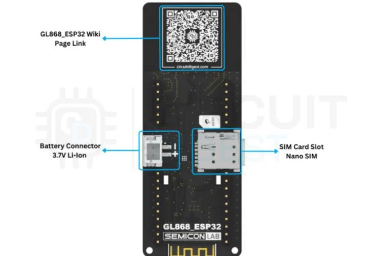
What Is the GeoLinker GL868 Board?
GeoLinker GL868 is an all-in-one ESP32 GPS + GSM IoT Development Board to build powerful IoT tracking and monitoring systems with this ESP32-S3 + SIM868-based development board, designed for GPS tracking, GSM communication, and cloud connectivity all in one compact PCB.
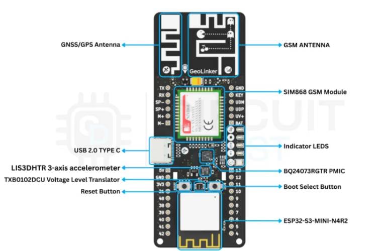
GeoLinker Key Features
- ESP32-S3 Powered - Dual-core 240MHz MCU with WiFi + BLE support
- Built-in GPS (GNSS) - Supports GPS, GLONASS, and BeiDou for accurate tracking
- GSM / GPRS Connectivity (SIM868) - Send data via HTTP, SMS, or calls
- LiPo charging + power management built-in
- Motion Detection (Accelerometer) - Wake-on-motion for ultra-low power tracking
- Onboard RGB + Status LEDs
- USB-C Programming & Charging
Block Diagram of the Interactive Voice Response System
The block diagram shows the complete flow of the IVRS system through five main blocks. At the top, the user with a mobile phone initiates the process by making a phone call over the GSM network. The call is received by the SIM868 GSM module, which handles call answering and detects the DTMF tones generated when the user presses phone keys. The SIM868 communicates with the ESP32-S3 GeoLinker via UART, which acts as the brain of the system, processing commands, managing the call flow, and deciding what action to take. From the ESP32, two outputs branch out. The first goes to the audio filter circuit, which conditions the audio signal and feeds it back into the SIM868 microphone input so the user can hear voice prompts during the call, shown by the dashed feedback line. The second output goes through the GPIO pins to control relays or the connected devices based on the key the user pressed on their phone.
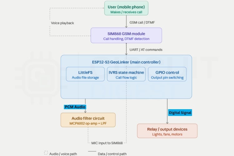
IVRS System Block Diagram - Signal Flow Summary
- User (Mobile Phone) - Initiates a phone call over the GSM network
- SIM868 GSM Module - Answers the call, detects DTMF keypad tones sent by the caller
- ESP32-S3 (GeoLinker) - Processes DTMF commands via UART, manages call state, triggers audio and GPIO
- Audio Filter Circuit - Conditions the sigma-delta GPIO signal into clean analog audio; feeds it back into SIM868 MIC input for voice playback
- Relay / GPIO Output - Controls connected electrical devices based on the key pressed
Circuit Diagram with Explanation for the IVRS
The circuit diagram shows how the main controller, op-amp, resistors, and capacitors are properly connected to complete the circuit. This circuit is used to convert the ESP32’s digital audio output from GPIO38 into a clean analog audio signal that can be given to the SIM868 module’s microphone input. Since ESP32 generates audio using sigma-delta modulation, the signal contains high-frequency switching noise and cannot be connected directly to the GSM module. So, this circuit acts as an audio conditioning stage.

First, capacitor C1 (1µF) removes the DC component from the GPIO38 output, and resistors R3 and R4 (100kΩ each) create a 1.65V bias voltage from the 3.3V supply. This provides a proper reference voltage for the op-amp stage. Then, resistor R2 and the MCP6002 operational amplifier with capacitors C2, C3, and C4 form a Sallen-Key low-pass filter, which removes the high-frequency noise and smooths the PWM/sigma-delta signal into proper analog audio.
After filtering, capacitor C6 again blocks unwanted DC components before sending the signal forward. Finally, resistors R5 (47kΩ) and R6 (2.2kΩ) form a voltage divider to reduce the signal level because SIM868 expects microphone-level input, not high-level audio. Capacitor C5 helps reduce noise and stabilize the MIC input. The final clean and reduced audio signal is then connected to the MIC+ and MIC− of the SIM868 module for voice playback during the IVRS call.
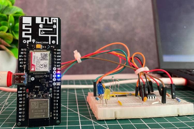
Hardware Setup for the ESP32 Interactive Voice Response System
The hardware connections shown below provide a clear picture of how the components are connected in real time to get a fully working setup.
How the Interactive Voice Response System Works - Step by Step
This section explains the full operational flow of the ESP32 interactive voice response system tutorial, from initial firmware configuration to real-time device control over a phone call.
Step 1 ⇒ Arduino IDE and Board Configuration
The proposed Interactive Voice Response System (IVRS) operates by integrating the ESP32-S3 microcontroller with the SIM868 GSM module to enable remote device control through a simple phone call. First, in the Arduino IDE, configure the board settings as follows: CPU frequency set to 240MHz, QIO flash mode at 80MHz, 4MB flash memory with SPIFFS/LittleFS partitioning, and QSPI PSRAM enabled to support efficient audio storage and processing. The system uses UART communication (UART0 / Hardware CDC) with an upload speed of 921600 bps for reliable communication with the GSM module. And don’t forget to install the GeoLinker library because this project needs to work properly.
Step 2 ⇒ Upload Audio Files to LittleFS
Next, install the ESP32 LittleFS uploader tool and use it to upload the voice files provided in the GitHub repository. If you don't know how to install and set up the LittleFS, just go through this tutorial, install the ESP32 LittleFS Uploader, and continue further. After flashing the main program, open the LittleFS uploader and upload the required audio files into the ESP32 memory.
Step 3 ⇒ Incoming Call Detection and Auto-Answer
When a user dials the phone number associated with the SIM868 module, the GSM module detects the incoming call and sends a “RING” notification to the ESP32 through UART communication. The system is programmed to automatically answer the call after a predefined number of rings. Once the call is answered, the ESP32 initializes the IVRS process by enabling DTMF (Dual Tone Multi-Frequency) detection in the SIM868 module, allowing it to recognize keypad inputs from the user’s phone. At the same time, the system prepares the audio playback mechanism.
Step 4 ⇒ Voice Prompt Playback Using Sigma-Delta Modulation
The ESP32 plays pre-recorded audio messages stored in its internal memory (LittleFS). These audio files are in raw PCM format and are converted into analog-like signals using sigma-delta modulation on a GPIO pin.
As a result, the user hears:
- A welcome message
- Followed by a menu prompt explaining available options
While the call is active, the user can press keys on their phone. Each key generates a unique DTMF tone, which is detected by the SIM868 module and sent to the ESP32.
DTMF Key Mapping - Default Command Table
| Key Pressed | Command | GPIO Action | Voice Confirmation |
| 1 | Turn ON Output 1 | GPIO4 → HIGH | "Output 1 turned ON" |
| 2 | Turn OFF Output 1 | GPIO4 → LOW | "Output 1 turned OFF" |
| 3 | Turn ON Output 2 | GPIO5 → HIGH | "Output 2 turned ON" |
| 4 | Turn OFF Output 2 | GPIO5 → LOW | "Output 2 turned OFF" |
| * | Repeat menu | No GPIO change | Menu audio replays |
| # | End call | No GPIO change | "Goodbye" + call disconnected |
Once a valid input is received, the ESP32 processes the command and controls the corresponding GPIO pins. These pins are connected to relays or other output devices, enabling real-time control of electrical appliances.
For example,
- Pressing ‘1’ sets GPIO4 HIGH → turns ON a device
- Pressing ‘2’ sets GPIO4 LOW → turns OFF the device
After executing the command, the system plays a confirmation message such as “Output 1 turned ON” or “Output 2 turned OFF,” ensuring immediate user feedback. If no input is received within a specified time, the system automatically ends the call to conserve resources. The user can also manually terminate the call by pressing ‘#’, after which a goodbye message is played, and the call is disconnected. After the call ends, the system resets to its idle state and continues to monitor for incoming calls, remaining ready for the next operation.
If more outputs need to be added, the system can be easily expanded by increasing the number of controlled GPIO pins and assigning new DTMF keys for each device. For example, to add Output 3, a new GPIO pin, such as GPIO6, can be included in the OUT_PINS[] array, and its corresponding name can be added in OUT_NAMES[]. Similarly, new audio confirmation files like output3_on.raw and output3_off.raw should be stored in LittleFS for voice feedback. The DTMF key mapping can then be extended so that key ‘5’ turns ON Output 3 and key ‘6’ turns OFF Output 3. In the same way, additional devices can be controlled by assigning the next available keypad numbers.
The IVRS menu audio should also be updated to inform the user about these new options. Since the code is designed using arrays and a scalable state machine, adding more outputs does not require major code changes
Code Explanation - ESP32 IVRS Firmware
The program is developed for the ESP32-S3 to implement an IVRS using the SIM868 GSM module. It integrates GSM communication, audio playback, DTMF detection, and output control into a single system. The code is structured in a modular way, with separate functions handling SIM communication, audio processing, and IVRS logic. A state machine is used to manage the call flow, including answering calls and processing user input. Audio files are stored in LittleFS and played using sigma-delta modulation. AT commands are used to control the SIM868 for call handling and network operations. The firmware for this ESP32 interactive voice response system is structured into four functional modules: GSM / AT-command handling, LittleFS audio playback via sigma-delta modulation, the IVRS state machine, and GPIO output control.
1. Includes, Defines, and Hardware Mapping
#include <Arduino.h>
#include <LittleFS.h>
#include <GL868_ESP32.h>
#define PIN_AUDIO_OUT 38
#define SIM_SERIAL (GeoLinker.modem.getSerial())
#define USB_SERIAL Serial
#define ANSWER_AFTER_RINGS 1
#define DTMF_WAIT_MS 30000
This section includes required libraries and defines core hardware connections like audio output pin, UART communication with SIM868, and system timing parameters. It also defines how many rings before answering and how long to wait for user input.
2. Output Pin Array and Audio File Paths
#define OUT_COUNT 2
static const uint8_t OUT_PINS[OUT_COUNT] = {4, 5};
#define AUD_WELCOME "/audio/welcome.raw"
#define AUD_MENU "/audio/menu.raw"
static const char *OUT_AUDIO_ON[OUT_COUNT] = {AUD_OUTPUT1_ON, AUD_OUTPUT2_ON};
Here, the system defines controllable outputs (like relays/lights) and maps them to GPIO pins. It also defines all audio files used in the IVRS system, including welcome message, menu, invalid input, and ON/OFF confirmations. Lookup tables connect outputs with their respective audio responses.
3. Sigma-Delta Audio Playback via Timer ISR
void IRAM_ATTR audio_isr() {
 if (g_audioPlaying) {
   sigmaDeltaWrite(PIN_AUDIO_OUT, g_audioBuf[g_audioPos++]);
 }
}
void audio_init() {
 sigmaDeltaAttach(PIN_AUDIO_OUT, SD_CARRIER_HZ);
 timerAttachInterrupt(g_audioTimer, &audio_isr);
}
This is a critical part: it generates audio using sigma-delta modulation on GPIO38. Audio files are loaded from LittleFS into memory and played using a timer interrupt (ISR). The ISR continuously sends audio samples to the output pin at 8kHz, creating analog audio after filtering.
4. IVRS State Machine
void ivrs_run() {
 switch (g_ivrsState) {
   case IVRS_PLAYING_WELCOME:
     audio_play_file(AUD_WELCOME);
     g_ivrsState = IVRS_PLAYING_MENU;
     break;
 }
}
void ivrs_handle_dtmf(char key) {
 if (key == '1') digitalWrite(OUT_PINS[0], HIGH);
}
This section controls the entire call flow using a state machine. It plays welcome and menu audio, waits for user input, and processes DTMF keys. Based on the key pressed, it turns outputs ON/OFF and plays confirmation audio. It also handles timeout and call termination.
5. Setup, Loop, and AT Command Handling
void handle_urc(const String &urc) {
 if (urc.indexOf("RING") >= 0) do_answer();
}
void setup() {
 GeoLinker.modem.begin();
 audio_init();
 sim_configure();
}
void loop() {
 if (SIM_SERIAL.available()) handle_urc(sim_read());
 ivrs_run();
}
This section handles GSM communication using AT commands. It detects incoming calls (RING), answers automatically, reads DTMF inputs, and manages call states. The setup() initializes everything (GPIO, LittleFS, SIM868, audio), and the loop() continuously processes modem messages and runs the IVRS state machine.
Troubleshooting the ESP32 IVRS
Issue 1: SIM868 Module Not Responding to AT Commands
Solution: Ensure that the UART connections between the ESP32 and SIM868 are correct, especially the TX and RX pins. Check if the baud rate matches in both the code and hardware configuration. Also, verify that the SIM868 module is properly powered and the PWRKEY sequence is correctly triggered during startup.
Issue 2: No Audio Heard During Call
Solution: Verify that the audio files are correctly stored in LittleFS and follow the required format (8kHz, 8-bit PCM). Check the low-pass filter circuit connections and ensure proper biasing to the MIC input of SIM868. Also, confirm that the GPIO used for audio output is functioning correctly.
Issue 3: Audio is Distorted or Noisy
Solution: Ensure the low-pass filter (Sallen-Key circuit) components are correctly connected and of proper values. Check the resistor divider going to the MIC input to avoid overdriving the signal. Also, verify proper grounding and minimise noise by keeping wires short.
Issue 4: System Restarts or Becomes Unstable
Solution: This usually happens due to an insufficient power supply. Ensure the SIM868 module gets a stable voltage and enough current during transmission. Use proper decoupling capacitors and avoid powering everything directly from weak USB sources.
In conclusion, this project shows how a reliable and efficient remote control system can be developed without depending on internet connectivity. By combining the ESP32-S3 with the SIM868 GSM module, the system provides a simple yet powerful solution that allows users to control devices using just a phone call.
The use of IVRS makes the interaction user-friendly, as it guides the user through voice prompts and responds instantly to keypad inputs. This not only improves accessibility but also ensures that the system can be used even in areas with limited or no internet access. Overall, this project gives the practical application of embedded systems and GSM communication in real-world scenarios. It serves as a strong foundation for building more advanced automation systems and proves that effective solutions can be created even with minimal resources and infrastructure. We also built an interesting project using Raspberry Pi, spare some time and look at our Low-Cost Interactive Voice Response (IVR) Device using Raspberry Pi for Automatic Calls and Messages for more details.
Frequently Asked Questions
1. What is the main purpose of this project?
This project is designed to control electrical devices remotely using a phone call. It allows users to interact with the system through voice prompts and keypad inputs without requiring internet connectivity.
2. Why is GSM used instead of Wi-Fi or IoT platforms?
GSM is used because it works in areas where internet connectivity is unavailable or unreliable. It provides a more stable and widely accessible communication method using basic cellular networks.
3. What is IVRS, and how does it work in this project?
IVRS (Interactive Voice Response System) is a technology that allows users to interact with a system through voice messages and keypad inputs. In this project, the system plays recorded messages and responds to user inputs via DTMF tones.
4. What are DTMF tones?
DTMF (Dual Tone Multi-Frequency) tones are the sounds generated when you press keys on a phone keypad. Each key has a unique frequency combination that the system detects and processes as commands.
5. Can this system work without the internet?
Yes, the system is completely independent of the internet. It operates using the GSM network, making it suitable for remote and rural applications.
6. What types of devices can be controlled using this system?
Any electrical device can be controlled, such as lights, fans, motors, or appliances, typically through relays connected to the ESP32 GPIO pins.
7. How is audio played to the user during the call?
Audio is stored in the ESP32’s memory and played using sigma-delta modulation. The signal is filtered and sent to the SIM868 module, which transmits it as voice during the call.
8. Is it possible to add more outputs to control additional devices?
Yes, the system is scalable. More outputs can be added by updating the code and connecting additional GPIO pins with relays or control circuits.
9. Where can this system be used in real life?
This system can be used in home automation, agriculture (motor control), industrial automation, security systems, and remote monitoring applications.
ESP32 IVRS GitHub Repository
The complete source code, wiring details, and project files are available in the GitHub repository for reference and reuse.


Voice Controlled Projects
Basic implementations of voice-based control systems for everyday electronics. These projects demonstrate how simple voice commands can be used to operate and automate devices.

Voice-Controlled LEDs using Arduino and Bluetooth
Voice-controlled LED system using Arduino and Bluetooth, where a smartphone app sends voice commands to control LEDs wirelessly

Low-Cost Offline Voice Recognition Module Alternatives to VC-02
Build an offline voice recognition system using the low-cost SU-03T module. Full wiring, SDK setup & firmware flash guide. The SU-03T is the cheapest alternative to the VC-02 offline voice module

Building a Voice-Controlled Home Automation System with Arduino
Arduino-based voice-controlled home automation uses a smartphone app and Bluetooth to control appliances like lights, fans, and TV with simple voice commands.
Complete Project Code
/**
* ============================================================
*  GL868_ESP32_IVRS — Interactive Voice Response System
*  Hardware: ESP32-S3 (4MB Flash, 2MB PSRAM) + SIM868
* ============================================================
*  Pin Map:
*    SIM868 UART   → GPIO17 (TX) / GPIO18 (RX)
*    SIM868 PWRKEY → GPIO42
*    SIM868 RI     → GPIO16
*    Audio Out     → GPIO38 → Sallen-Key LPF (MCP6002/LMV358)
*                          → 47kΩ/2kΩ divider → SIM868 MIC+
*    Output 1      → GPIO4   (e.g. Relay / Light 1)
*    Output 2      → GPIO5   (e.g. Relay / Light 2)
*    Status LED    → GPIO47
*    Battery ADC   → GPIO1
*
*  Audio:
*    Sigma-Delta on GPIO38, recovered by external LPF.
*    Files in LittleFS /audio/*.raw
*    Format: 8000 Hz, 8-bit Unsigned PCM, Mono, RAW (no header)
*
*  IVRS Key Map (during call):
*    1 → Output 1 ON       2 → Output 1 OFF
*    3 → Output 2 ON       4 → Output 2 OFF
*    * → Repeat menu       # → End call
*
*  To add more outputs: increase OUT_COUNT and fill OUT_PINS[].
* ============================================================
*/
#include <Arduino.h>
#include <LittleFS.h>
#include <GL868_ESP32.h>
// ── Pin Map ──────────────────────────────────────────────────────────────────
#define PIN_AUDIO_OUT 38 // Sigma-delta → LPF → SIM868 MIC+
// ── Controlled Outputs ───────────────────────────────────────────────────────
// To add outputs: increase OUT_COUNT, add a pin, name, and two audio file
// paths.
#define OUT_COUNT 2
static const uint8_t OUT_PINS[OUT_COUNT] = {4, 5};
static const char *OUT_NAMES[OUT_COUNT] = {"Output 1", "Output 2"};
// ── Serial ───────────────────────────────────────────────────────────────────
#define SIM_SERIAL (GeoLinker.modem.getSerial())
#define USB_SERIAL Serial
#define USB_BAUD 115200
// ── Timing ───────────────────────────────────────────────────────────────────
#define BOOT_TIMEOUT_MS 35000
#define AT_TIMEOUT_MS 3000
#define ANSWER_AFTER_RINGS 1 // auto-answer after this many rings
#define DTMF_WAIT_MS 30000   // hang up if no key within this time
// ── Audio file paths ─────────────────────────────────────────────────────────
// Shared prompts
#define AUD_WELCOME "/audio/welcome.raw"
#define AUD_MENU "/audio/menu.raw"
#define AUD_INVALID "/audio/invalid.raw"
#define AUD_GOODBYE "/audio/goodbye.raw"
// Per-output confirmation — rename the filenames here to match what you record
#define AUD_OUTPUT1_ON "/audio/output1_on.raw"
#define AUD_OUTPUT1_OFF "/audio/output1_off.raw"
#define AUD_OUTPUT2_ON "/audio/output2_on.raw"
#define AUD_OUTPUT2_OFF "/audio/output2_off.raw"
// Lookup tables (reference the #defines above — no need to edit these)
static const char *OUT_AUDIO_ON[OUT_COUNT] = {AUD_OUTPUT1_ON, AUD_OUTPUT2_ON};
static const char *OUT_AUDIO_OFF[OUT_COUNT] = {AUD_OUTPUT1_OFF,
                                              AUD_OUTPUT2_OFF};
// ── Audio engine constants
// ────────────────────────────────────────────────────
#define AUDIO_SAMPLE_HZ 8000 // playback sample rate
#define SD_CARRIER_HZ 312500 // sigma-delta carrier frequency
#define AUDIO_SILENCE 128    // 50% duty = DC bias = no audio
// ════════════════════════════════════════════════════════════════════════════
//  GLOBALS
// ════════════════════════════════════════════════════════════════════════════
// Audio playback
static volatile uint8_t *g_audioBuf = nullptr;
static volatile size_t g_audioLen = 0;
static volatile size_t g_audioPos = 0;
static volatile bool g_audioPlaying = false;
static hw_timer_t *g_audioTimer = nullptr;
// IVRS state
typedef enum {
 IVRS_IDLE,
 IVRS_PLAYING_WELCOME,
 IVRS_PLAYING_MENU,
 IVRS_WAITING_DTMF,
 IVRS_HANGING_UP
} ivrs_state_t;
static ivrs_state_t g_ivrsState = IVRS_IDLE;
static volatile char g_dtmfKey = 0;
static uint32_t g_dtmfTimer = 0;
// SIM868 state
static bool g_simReady = false;
static bool g_inCall = false;
static uint8_t g_ringCount = 0;
static volatile bool g_riTriggered = false;
// ── Forward declarations ─────────────────────────────────────────────────────
void sim_configure();
bool sim_at(const char *cmd, const char *expect,
           uint32_t timeout_ms = AT_TIMEOUT_MS, String *out = nullptr);
String sim_read(uint32_t timeout_ms = AT_TIMEOUT_MS);
void sim_flush();
void do_answer();
void do_hangup();
void handle_urc(const String &urc);
bool audio_load(const char *path);
void audio_play();
void audio_stop();
void audio_wait(uint32_t timeout_ms = 30000);
void audio_play_file(const char *path);
void ivrs_run();
void ivrs_call_answered();
void ivrs_call_ended();
void ivrs_handle_dtmf(char key);
void led_status(bool on);
void IRAM_ATTR ri_isr();
void IRAM_ATTR audio_isr();
// ── Custom RGB LED ───────────────────────────────────────────────────────────
enum CustomLED { L_OFF, L_BOOT, L_INIT, L_IDLE, L_RING, L_CALL, L_ERR };
CustomLED g_rgbState = L_OFF;
void set_rgb(CustomLED s) { g_rgbState = s; }
void rgb_run() {
 static uint32_t lastTick = 0;
 static uint32_t blinkPhase = 0;
 static CustomLED lastState = L_OFF;
 uint32_t now = millis();
 if (g_rgbState != lastState) {
   lastState = g_rgbState;
   lastTick = 0; // Force immediate update
   blinkPhase = 0;
 }

 switch(g_rgbState) {
   case L_OFF:
     if (lastTick == 0) {
       neopixelWrite(GL868_ESP32_WS2812B_PIN, 0, 0, 0);
       lastTick = now;
     }
     break;
   case L_BOOT: // Yellow
     if (lastTick == 0) {
       neopixelWrite(GL868_ESP32_WS2812B_PIN, 32, 32, 0);
       lastTick = now;
     }
     break;
   case L_INIT: // Magenta blink
     if (lastTick == 0 || now - lastTick > (blinkPhase ? 250 : 1750)) {
       lastTick = now;
       blinkPhase = !blinkPhase;
       if (blinkPhase) neopixelWrite(GL868_ESP32_WS2812B_PIN, 32, 0, 32);
       else neopixelWrite(GL868_ESP32_WS2812B_PIN, 0, 0, 0);
     }
     break;
   case L_IDLE: // Green blink
     if (lastTick == 0 || now - lastTick > (blinkPhase ? 250 : 1750)) {
       lastTick = now;
       blinkPhase = !blinkPhase;
       if (blinkPhase) neopixelWrite(GL868_ESP32_WS2812B_PIN, 0, 32, 0);
       else neopixelWrite(GL868_ESP32_WS2812B_PIN, 0, 0, 0);
     }
     break;
   case L_RING: // R G B flash
     {
       uint32_t p = (now / 150) % 4;
       if (lastTick == 0 || p != blinkPhase) {
         lastTick = now;
         blinkPhase = p;
         if (p == 0) neopixelWrite(GL868_ESP32_WS2812B_PIN, 32, 0, 0);
         else if (p == 1) neopixelWrite(GL868_ESP32_WS2812B_PIN, 0, 32, 0);
         else if (p == 2) neopixelWrite(GL868_ESP32_WS2812B_PIN, 0, 0, 32);
         else neopixelWrite(GL868_ESP32_WS2812B_PIN, 0, 0, 0);
       }
     }
     break;
   case L_CALL: // Blue blink
     if (lastTick == 0 || now - lastTick > (blinkPhase ? 250 : 1750)) {
       lastTick = now;
       blinkPhase = !blinkPhase;
       if (blinkPhase) neopixelWrite(GL868_ESP32_WS2812B_PIN, 0, 0, 32);
       else neopixelWrite(GL868_ESP32_WS2812B_PIN, 0, 0, 0);
     }
     break;
   case L_ERR: // Red
     if (lastTick == 0 || now - lastTick > 200) {
       lastTick = now;
       blinkPhase = !blinkPhase;
       if (blinkPhase) neopixelWrite(GL868_ESP32_WS2812B_PIN, 32, 0, 0);
       else neopixelWrite(GL868_ESP32_WS2812B_PIN, 0, 0, 0);
     }
     break;
 }
}
// ════════════════════════════════════════════════════════════════════════════
//  AUDIO ENGINE
// ════════════════════════════════════════════════════════════════════════════
void IRAM_ATTR audio_isr() {
 if (g_audioPlaying) {
   if (g_audioPos < g_audioLen) {
     sigmaDeltaWrite(PIN_AUDIO_OUT, g_audioBuf[g_audioPos++]);
   } else {
     g_audioPlaying = false;
     sigmaDeltaWrite(PIN_AUDIO_OUT, AUDIO_SILENCE);
   }
 }
}
void audio_init() {
 sigmaDeltaAttach(PIN_AUDIO_OUT, SD_CARRIER_HZ);
 sigmaDeltaWrite(PIN_AUDIO_OUT, AUDIO_SILENCE);
 // Timer fires at AUDIO_SAMPLE_HZ to push next sample
 g_audioTimer = timerBegin(1000000UL); // 1 MHz base
 timerAttachInterrupt(g_audioTimer, &audio_isr);
 timerAlarm(g_audioTimer, 1000000UL / AUDIO_SAMPLE_HZ, true, 0);
 USB_SERIAL.println(F("[AUDIO] init OK — 8 kHz sigma-delta on GPIO38"));
}
// Load file from LittleFS into PSRAM (falls back to heap)
bool audio_load(const char *path) {
 audio_stop();
 File f = LittleFS.open(path, "r");
 if (!f) {
   USB_SERIAL.printf("[AUDIO] Not found: %s\n", path);
   return false;
 }
 size_t len = f.size();
 if (len == 0) {
   f.close();
   return false;
 }
 if (g_audioBuf) {
   free((void *)g_audioBuf);
   g_audioBuf = nullptr;
 }
 // Prefer PSRAM so we don't fragment heap
 uint8_t *buf = (uint8_t *)ps_malloc(len);
 if (!buf)
   buf = (uint8_t *)malloc(len);
 if (!buf) {
   USB_SERIAL.printf("[AUDIO] OOM: %u bytes for %s\n", (unsigned)len, path);
   f.close();
   return false;
 }
 f.read(buf, len);
 f.close();
 g_audioBuf = buf;
 g_audioLen = len;
 g_audioPos = 0;
 USB_SERIAL.printf("[AUDIO] Loaded %s (%u B)\n", path, (unsigned)len);
 return true;
}
void audio_play() {
 if (g_audioBuf && g_audioLen > 0) {
   g_audioPos = 0;
   g_audioPlaying = true;
 }
}
void audio_stop() {
 g_audioPlaying = false;
 sigmaDeltaWrite(PIN_AUDIO_OUT, AUDIO_SILENCE);
}
// Block until done or timeout; drains SIM868 URCs while waiting.
// Stops immediately if a DTMF key arrives (barge-in / type-ahead).
void audio_wait(uint32_t timeout_ms) {
 uint32_t start = millis();
 while (g_audioPlaying) {
   rgb_run();
   if (millis() - start > timeout_ms) {
     audio_stop();
     return;
   }
   if (g_dtmfKey) {
     audio_stop();
     return;
   } // DTMF received → stop audio now
   if (SIM_SERIAL.available()) {
     String u = sim_read(100);
     if (u.length())
       handle_urc(u);
   }
   delay(5);
 }
 delay(150); // brief inter-phrase gap
}
// Convenience: load → play → wait (no-op if file missing)
void audio_play_file(const char *path) {
 if (audio_load(path)) {
   audio_play();
   audio_wait();
 }
}
// ════════════════════════════════════════════════════════════════════════════
//  IVRS STATE MACHINE
// ════════════════════════════════════════════════════════════════════════════
void ivrs_run() {
 switch (g_ivrsState) {
 case IVRS_IDLE:
   break;
 case IVRS_PLAYING_WELCOME:
   audio_play_file(AUD_WELCOME);
   if (!g_inCall)
     break; // caller hung up during playback
   g_ivrsState = IVRS_PLAYING_MENU;
   break; // fall into menu on next loop tick
 case IVRS_PLAYING_MENU:
   g_dtmfKey = 0; // clear before playing
   audio_play_file(AUD_MENU);
   if (!g_inCall)
     break;
   g_dtmfTimer = millis();
   // If barge-in happened during menu, don't clear it!
   // We go straight to WAITING_DTMF where the loop will catch it instantly.
   g_ivrsState = IVRS_WAITING_DTMF;
   break;
 case IVRS_WAITING_DTMF: {
   char k = g_dtmfKey;
   if (k) {
     g_dtmfKey = 0;
     ivrs_handle_dtmf(k); // handles action + transitions state
   } else if (millis() - g_dtmfTimer > DTMF_WAIT_MS) {
     USB_SERIAL.println(F("[IVRS] No key — hanging up."));
     g_ivrsState = IVRS_HANGING_UP;
   }
   break;
 }
 case IVRS_HANGING_UP:
   if (g_inCall)
     audio_play_file(AUD_GOODBYE);
   do_hangup();
   g_ivrsState = IVRS_IDLE;
   break;
 }
}
void ivrs_handle_dtmf(char key) {
 USB_SERIAL.printf("[IVRS] DTMF: '%c'\n", key);
 audio_stop();
 if (key == '#') {
   g_ivrsState = IVRS_HANGING_UP;
   return;
 }
 if (key == '*') {
   g_ivrsState = IVRS_PLAYING_MENU;
   return;
 }
 // Keys 1-4 control outputs
 // Key 1 → OUT[0] ON,  Key 2 → OUT[0] OFF
 // Key 3 → OUT[1] ON,  Key 4 → OUT[1] OFF
 // Pattern: key '1' = index 0, turn ON;  key '2' = index 0, turn OFF; etc.
 int k = key - '1';          // '1'→0 '2'→1 '3'→2 '4'→3
 int outIdx = k / 2;         // which output (0 or 1)
 bool turnOn = (k % 2 == 0); // even → ON, odd → OFF
 if (outIdx >= 0 && outIdx < OUT_COUNT) {
   bool current = digitalRead(OUT_PINS[outIdx]);
   if (turnOn == (bool)current) {
     // Already in that state — still play confirmation
   }
   digitalWrite(OUT_PINS[outIdx], turnOn ? HIGH : LOW);
   USB_SERIAL.printf("[IVRS] %s → %s\n", OUT_NAMES[outIdx],
                     turnOn ? "ON" : "OFF");
   audio_play_file(turnOn ? OUT_AUDIO_ON[outIdx] : OUT_AUDIO_OFF[outIdx]);
 } else {
   audio_play_file(AUD_INVALID);
 }
 if (g_inCall) {
   g_dtmfKey = 0;          // clear the consumed key
   g_dtmfTimer = millis(); // reset timeout
   g_ivrsState = IVRS_WAITING_DTMF;
 }
}
void ivrs_call_answered() {
 USB_SERIAL.println(F("[IVRS] Call answered — IVRS starting."));
 // Enable DTMF detection; SIM868 sends +DTMF: X URC
 sim_at("AT+DDET=1,0,1", "OK", 3000);
 // Reduce mic gain — our line-level signal is much stronger than a mic
 sim_at("AT+CMIC=0,10", "OK");
 g_ivrsState = IVRS_PLAYING_WELCOME;
}
void ivrs_call_ended() {
 USB_SERIAL.println(F("[IVRS] Call ended."));
 audio_stop();
 g_inCall = false;
 g_ringCount = 0;
 g_dtmfKey = 0;
 g_ivrsState = IVRS_IDLE;
 sim_at("AT+DDET=0", "OK", 2000); // disable DTMF detection
 set_rgb(L_IDLE);
}
// ════════════════════════════════════════════════════════════════════════════
//  SIM868 POWER & BOOT
// ════════════════════════════════════════════════════════════════════════════

// Wait for SIM868 to register on the GSM network.
// Returns TRUE  → Registered Home or Roaming (or Timeout override)
bool sim_wait_ready() {
 USB_SERIAL.print(F("[SIM] Waiting for network registration"));
 uint32_t start = millis();
 while (millis() - start < 15000) {
   sim_flush();
   SIM_SERIAL.println("AT+CREG?");
   String r = sim_read(1000);
   if (r.indexOf("+CREG: 0,1") >= 0 || r.indexOf("+CREG: 0,5") >= 0 ||
       r.indexOf("+CREG: 1,1") >= 0 || r.indexOf("+CREG: 1,5") >= 0 ||
       r.indexOf("+CREG: 2,1") >= 0 || r.indexOf("+CREG: 2,5") >= 0) {
     USB_SERIAL.println(F("\n[SIM] Registered!"));
     return true;
   }
   USB_SERIAL.print('.');
   uint32_t waitStart = millis();
   while (millis() - waitStart < 1000) {
     rgb_run();
     delay(10);
   }
 }
 USB_SERIAL.println(F("\n[SIM] Registration timeout/failed, proceeding anyway..."));
 return true;
}
void sim_configure() {
 sim_at("ATE0", "OK");
 sim_at("AT+CMGF=1", "OK");
 sim_at("AT+CNMI=2,1,0,0,0", "OK");
 sim_at("AT+CLIP=1", "OK");
 sim_at("AT+CLVL=80", "OK");   // speaker volume
 sim_at("AT+CMIC=0,10", "OK"); // mic gain
 sim_at("AT+DDET=0", "OK");    // DTMF off until call
 // Fix: only detach if previously attached, avoids GPIO ISR error on first
 // boot
 static bool s_riAttached = false;
 if (s_riAttached)
   detachInterrupt(digitalPinToInterrupt(GL868_ESP32_RI_PIN_DEFAULT));
 attachInterrupt(digitalPinToInterrupt(GL868_ESP32_RI_PIN_DEFAULT), ri_isr, FALLING);
 s_riAttached = true;
 g_simReady = true;
 g_inCall = false;
 g_ringCount = 0;
 set_rgb(L_IDLE);
 USB_SERIAL.println(F("[SIM] Ready.\n[IVRS] Waiting for calls..."));
}
// ════════════════════════════════════════════════════════════════════════════
//  SIM868 AT HELPERS
// ════════════════════════════════════════════════════════════════════════════
bool sim_at(const char *cmd, const char *expect, uint32_t timeout_ms,
           String *out) {
 sim_flush();
 SIM_SERIAL.println(cmd);
 String resp = sim_read(timeout_ms);
 if (out)
   *out = resp;
 bool ok = resp.indexOf(expect) >= 0;
 USB_SERIAL.printf("[AT] %-28s → %s\n", cmd, ok ? "OK" : "FAIL");
 return ok;
}
String sim_read(uint32_t timeout_ms) {
 String r;
 uint32_t deadline = millis() + timeout_ms;
 while (millis() < deadline) {
   rgb_run();
   while (SIM_SERIAL.available()) {
     r += (char)SIM_SERIAL.read();
     deadline = millis() + 50;
   }
   delay(1);
 }
 r.trim();
 return r;
}
void sim_flush() {
 delay(30);
 while (SIM_SERIAL.available())
   SIM_SERIAL.read();
}
void do_answer() {
 USB_SERIAL.println(F("[SIM] Answering..."));
 if (sim_at("ATA", "OK", 8000)) {
   set_rgb(L_CALL);
   g_inCall = true;
   g_ringCount = 0;
   ivrs_call_answered();
 }
}
void do_hangup() {
 sim_at("ATH", "OK", 5000);
 ivrs_call_ended();
}
// ════════════════════════════════════════════════════════════════════════════
//  URC HANDLER — receives all unsolicited modem messages
// ════════════════════════════════════════════════════════════════════════════
void handle_urc(const String &urc) {
 if (!urc.length())
   return;
 USB_SERIAL.print(F("[SIM] "));
 USB_SERIAL.println(urc);
 // ── Incoming ring ────────────────────────────────────────────────────
 if (urc.indexOf("RING") >= 0 && !g_inCall) {
   set_rgb(L_RING);
   g_ringCount++;
   USB_SERIAL.printf("[IVRS] Ring #%d\n", g_ringCount);
   if (g_ringCount >= ANSWER_AFTER_RINGS)
     do_answer();
 }
 // ── DTMF: +DTMF: X ───────────────────────────────────────────────────
 if (urc.indexOf("+DTMF:") >= 0) {
   int p = urc.indexOf("+DTMF:");
   String s = urc.substring(p + 6);
   s.trim();
   if (s.length() > 0) {
     g_dtmfKey = s.charAt(0);
     USB_SERIAL.printf("[IVRS] DTMF captured: '%c'\n", g_dtmfKey);
   }
 }
 // ── Call dropped by remote ────────────────────────────────────────────
 if (urc.indexOf("NO CARRIER") >= 0 || urc.indexOf("NO ANSWER") >= 0 ||
     urc.indexOf("BUSY") >= 0) {
   if (g_inCall)
     ivrs_call_ended();
   g_ringCount = 0;
 }
 // ── SIM868 unexpected power-down ─────────────────────────────────────
 if (urc.indexOf("NORMAL POWER DOWN") >= 0) {
   g_simReady = false;
   if (g_inCall)
     ivrs_call_ended();
   USB_SERIAL.println(F("[SIM] Power down! Restarting in 3 s..."));
   set_rgb(L_ERR);
   delay(3000);
   set_rgb(L_BOOT);
   if (GeoLinker.modem.powerOn()) {
     sim_wait_ready(); // wait for audio/SMS subsystem before configuring
     sim_configure();
   } else {
     USB_SERIAL.println(F("[FATAL] SIM868 did not recover!"));
     set_rgb(L_ERR);
     while (true) {
       delay(100);
     }
   }
 }
}
// ════════════════════════════════════════════════════════════════════════════
//  SETUP
// ════════════════════════════════════════════════════════════════════════════
void setup() {
 USB_SERIAL.begin(USB_BAUD);
 delay(400);
 USB_SERIAL.println(
     F("\n[IVRS] ============================================"));
 USB_SERIAL.println(F("[IVRS]  GL868_ESP32_IVRS  —  ESP32-S3 + SIM868"));
 USB_SERIAL.println(F("[IVRS] ============================================"));
 // Initialise RGB LED manually
 pinMode(GL868_ESP32_WS2812B_POWER_PIN, OUTPUT);
 digitalWrite(GL868_ESP32_WS2812B_POWER_PIN, HIGH);
 delay(10);
 set_rgb(L_BOOT);
 pinMode(GL868_ESP32_RI_PIN_DEFAULT, INPUT_PULLUP);
 // Initialise controlled output GPIOs
 for (int i = 0; i < OUT_COUNT; i++) {
   pinMode(OUT_PINS[i], OUTPUT);
   digitalWrite(OUT_PINS[i], LOW);
   USB_SERIAL.printf("[IVRS] %s → GPIO%d = OFF\n", OUT_NAMES[i], OUT_PINS[i]);
 }
 // LittleFS
 if (!LittleFS.begin(true)) {
   USB_SERIAL.println(
       F("[FS]   LittleFS MOUNT FAILED — audio will not play!"));
 } else {
   USB_SERIAL.println(F("[FS]   LittleFS mounted OK."));
   // List audio files present
   File root = LittleFS.open("/audio");
   if (root && root.isDirectory()) {
     File f = root.openNextFile();
     while (f) {
       USB_SERIAL.printf("[FS]   Found: /audio/%s (%u B)\n", f.name(),
                         (unsigned)f.size());
       f = root.openNextFile();
     }
   } else {
     USB_SERIAL.println(
         F("[FS]   /audio not found — upload audio files via LittleFS tool!"));
   }
 }
 // SIM868 UART
 GeoLinker.modem.begin();
 delay(100);
 // Audio engine
 audio_init();
 // SIM868 power-on + boot + configuration
 // Retry loop: handles the case where modem powers down mid-startup
 while (true) {
   set_rgb(L_BOOT);
   if (!GeoLinker.modem.powerOn()) {
     USB_SERIAL.println(F("[FATAL] SIM868 boot failed!"));
     set_rgb(L_ERR);
     while (true) {
       delay(100);
     }
   }
   set_rgb(L_INIT);
   if (sim_wait_ready())
     break; // ready → proceed to configure
   // NORMAL POWER DOWN during wait — pulse power and retry
   USB_SERIAL.println(F("[SIM] Retrying boot in 3 s..."));
   delay(3000);
 }
 sim_configure();
}
// ════════════════════════════════════════════════════════════════════════════
//  MAIN LOOP
// ════════════════════════════════════════════════════════════════════════════
void loop() {
 // Service SIM868 URCs
 if (SIM_SERIAL.available()) {
   String urc = sim_read(400);
   if (urc.length())
     handle_urc(urc);
 }
 // Advance IVRS state machine
 ivrs_run();

 // Advance RGB state
 rgb_run();
}
// ════════════════════════════════════════════════════════════════════════════
//  MISC
// ════════════════════════════════════════════════════════════════════════════
void IRAM_ATTR ri_isr() { g_riTriggered = true; }
