

Hi guys, are you a newbie to the world of Robotics or Electronic? OR Are you looking for a simple yet powerful project to make your friends and teachers impressed? Then this is the place.
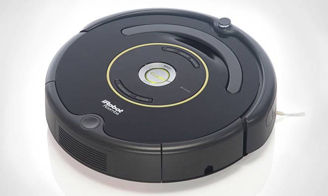
In this project we will use the power of Embedded Systems and Electronics to make our own robot which could help us in keeping our home or work place neat and tidy. This robot is simple four wheeled Vacuum Cleaner which could smartly avoid obstacles and vacuum the floor at the same time. The idea is inspired by the famous vacuum cleaner Robot Roomba which is shown in the image below.
Our Idea is to make a simple robot right from the scratch which can automatically avoid the obstacles while cleaning the floor. Trust me people it's fun!!
Required Material and Components:
Okay so now we have the Idea of our Automatic Floor Cleaner Robot in mind and we know what we are up to. So let's look where we should start our execution. In order to build a robot of our idea we would first need to decide on the following:
- Microcontroller type
- Sensors required
- Motors required
- Robot chassis material
- Battery capacity
Now, lets us decide on each of the above mentioned points. This way it will be helpful for you to not only build this home cleaning robot but also any other robots which strikes your imagination.
Microcontroller Type:
Selecting the Microcontroller is a very important task, as this controller will act as the brain of your robot. Most of the DIY projects are made around Arduino and Raspberry Pi, but doesn't have to be the same. There is no specific Microcontroller that you can work on. It all depends upon the requirement and cost.
Like a Tablet cannot be designed on 8 bit Microcontroller and there is no worth of using ARM cortex m4 to design an electronic calculator.
Microcontroller selection totally depends upon the requirements of the product:
1. Firstly technical requirements are identified like number of I/O pins required, flash size, number/type of communication protocols, any special features etc.
2. Then list of controllers are selected as per the technical requirements. This list contains controllers from different manufacturers. Many application specific controllers are available.
3. Then a controller is finalized based upon cost, availability and support from manufacturer.
If you don't want to do lot of heavy lifting and just want to learn the basics of microcontrollers and then later get deep into it, then you can choose Arduino. In this project we will be using an Arduino. We have previously created many types of Robots using Arduino:
- DTMF Controlled Robot using Arduino
- Line Follower Robot using Arduino
- Computer Controlled Robot using Arduino
- WiFi Controlled Robot using Arduino
- Accelerometer Based Hand Gesture Controlled Robot using Arduino
- Bluetooth Controlled Toy Car using Arduino
Sensors Required:
There are a lot of sensors available in the market each having its own usage. Every robot gets input via a sensor, they act as the sensory organs for the Robot. In our case our robot should be able to detect obstacles and avoid them.
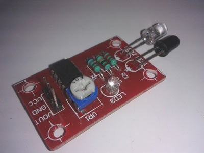
There a lot of other cool sensor which we will be using in our future projects, but now let us stay focused on IR sensor and US (Ultrasonic sensor) as these two guys will be providing the vision for our robo-car. Check out the working of IR sensor here. Below showing pictures of IR sensor Module and Ultrasonic Sensor:
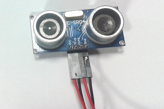
Ultrasonic Sensor consists of two circular eyes out of which one is used to transmit the US signal and the other to receive the US rays. The time taken by the rays to get transmitted and received back is calculated by the microcontroller. Now, since the time and speed of sound is known we can calculate the distance by the following formulae.
- Distance = Time x Speed of Sound divided by 2
The value is divided by two since the ray travels forward and backward covering the same distance. Detailed explanation of using Ultrasonic sensor is given here.
Motors required:
There are quite a lot a motors used in the field of robotics the most used ones are the Stepper and Servo motor. Since this project does not have any complicated actuators or rotary encoder we will be using a normal PMDC Motor. But our battery is a bit bulky and heavy hence we use four motors to drive our robot all four being the same PMDC motors. But it is advisable to set into stepper and servo motors once you get comfortable with PMDC motors.
Robot chassis material:
As a student or hobbyist the most difficult part while making a robot is to prepare the chassis of our robot. The problem is with the availability of tools and material. The most ideal material for this project will be Acrylic, but it requires drillers and other tools to work with it. Hence wood is chosen that everyone can work on it with ease.
This problem has totally vanished from the field after the introduction of the 3D printers. I am planning to 3D print parts someday and update you people with the same. So for now let’s use wooden sheets to build our robot.
Battery capacity:
Selecting the battery capacity should be our last part of work because it purely depends on your chassis and motors. Here our battery should drive a vacuum cleaner which draws about 3-5A and four PMDC motors. Hence we will require a heavy battery. I have chosen 12V 20Ah SLAB (Sealed lead acid battery) and its pretty bulky making our robot get four PMDC motors to pull this bulky guy.
Now that we have selected all our Required Components lets list them down
- Wooden sheets for chassis
- IR and US sensors
- Vacuum cleaner which runs on DC current
- Arduino Uno
- 12V 20Ah battery
- Motor driver IC (L293D)
- Working tools
- Connecting wires
- Enthusiastic energy to learn and work.
Most of our components are covered in the description above, I will explain the left outs below.
DC vacuum cleaner:
Since our robot runs on a 12V 20Ah DC system. Our vacuum should also be a 12V DC vacuum cleaner. If you are confused on where to get one then you can visit eBay or Amazon for car cleaning vacuum cleaners.
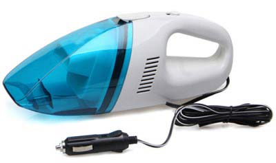
We will be using the same as shown in above picture.
Motor driver (L293D):
A motor driver is a intermediate module between Arduino and the Motor. This is because Arduino microcontroller will not be able to supply the current required for the motor to work it and can just supply 40mA, hence drawing more current will damage the controller permanently. So we trigger the motor driver which in turn controls the motor.
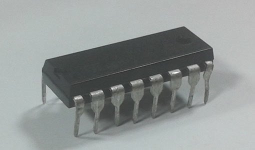
We will be using L293D Motor Driver IC which will be able to supply up to 1A, hence this driver will get the information from Arduino and make the motor work as desired.
Thats it!! I have given most of the crucial information but before we start building the robot it is recommended to go through the datasheet of L293D and Arduino. If you have any doubts or problems you can contact us through the comment section.
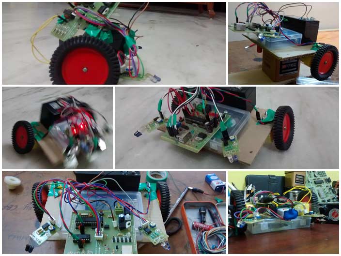
Building and Testing the Robot:
The Vacuum Cleaner is the most crucial part in placement of Robot. It has to be placed at tilted angle as shown in the picture, so that it can provide proper vacuum action. The vacuum cleaner is not controlled by the Arduino. Once you power on the robot the vacuum is also turned on.
One tiring process of building our Robot is the wooden works. We have to carve our wood and drill some holes to place the sensors and vacuum cleaner.
It is recommended to Test Ride your Robot with the following code once you arrange the Motor and Motor driver, before connecting the Sensors.
void setup()
{
Serial.begin(9600);
pinMode(9,OUTPUT);
pinMode(10,OUTPUT);
pinMode(11,OUTPUT);
pinMode(12,OUTPUT);
}
void loop()
{
delay(1000);
Serial.print("forward");
digitalWrite(9,HIGH);
digitalWrite(10,LOW);
digitalWrite(11,HIGH);
digitalWrite(12,LOW);
delay(500);
Serial.print("backward");
digitalWrite(9,LOW);
digitalWrite(10,HIGH);
digitalWrite(11,LOW);
digitalWrite(12,HIGH);
}
If everything works fine then you can connect the sensors with Arduino as shown in Circuit Diagram and use the Full Code given at the end. As you can see I have mounted an Ultrasonic sensor to the front and two IR sensors on both the side of the robot. The heat sink is fitted on to the L293D just in case the IC heats up fast.
You can also add few extra parts like this one
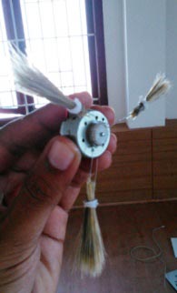
This is a Sweeping Arrangement can be placed on both ends of the front part that will push the dust along the sides into the suction area.
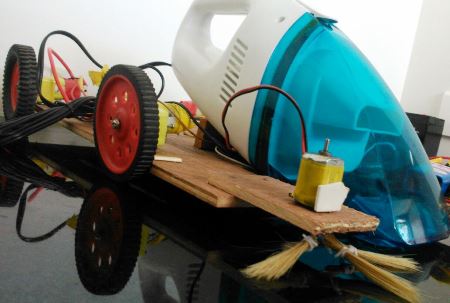
Further, you also have an option of making a Smaller Version of this Vacuum Cleaning Robot like this
This smaller Robot is made on cardboard and runs on ATMega16 development board. The vacuum cleaner part was done by using a BLDC fan and enclosed in a box. You can adopt this if you want to keep your budget low. This idea also works but it's not efficient.
Circuit Diagram:

The Code for this Vacuum Cleaner Robot can be found in the Code Section below. Once the connection is done and program is dumped into Arduino, your robot is ready to get into action. The working of the code is explained using the comments. If you want to see this robot in action, check out the Video below.
Further, I am also planning to completely 3D Printed the parts in its next version. I am also going to be adding few cool features and complex algorithms so that it covers the whole carpet area and easy to handle and compact in size. So stay tuned for future updates.
Complete Project Code
#define trigPin 12
#define echoPin 13
#define ir1 7
#define ir2 6
void setup()
{
  Serial.begin(9600);
  pinMode(8,OUTPUT);
  pinMode(9,OUTPUT);
  pinMode(10,OUTPUT);
  pinMode(11,OUTPUT);
  pinMode(trigPin, OUTPUT);
  pinMode(echoPin, INPUT);
  pinMode(ir1, INPUT);
  pinMode(ir2,INPUT);
}
void loop()
{
  int duration, distance;
  int flag,val1,val2;
  val1=digitalRead(ir1);
  val2=digitalRead(ir2);
  Serial.println(val1);
  Serial.println(val2);
  digitalWrite(trigPin, HIGH);
  delayMicroseconds(1000);
  digitalWrite(trigPin, LOW);
  duration = pulseIn(echoPin, HIGH);
  distance = (duration/2) / 29.1;
  if (distance >= 200 || distance <= 0){
    Serial.println("Out of range");
  }
  else {
    Serial.print(distance);
    Serial.println(" cm");
  }
  delay(500);
if (distance >=20)
{
  delay(100);
  Serial.println("forward");
  digitalWrite(8,HIGH);
  digitalWrite(9,LOW);
  digitalWrite(10,HIGH);
  digitalWrite(11,LOW);
  delay(150);
  Serial.println("STOP");
  digitalWrite(8,LOW);
  digitalWrite(9,LOW);
  digitalWrite(10,LOW);
  digitalWrite(11,LOW);
}
if (distance<=20)
{
  if (val1==1 )
  {
    Serial.print("turn right");
    digitalWrite(8,LOW);
    digitalWrite(9,LOW);
    digitalWrite(10,HIGH);
    digitalWrite(11,LOW);
    delay(2000);
  }
  if (val2==1)
  {
    Serial.print("turn left");
    digitalWrite(8,HIGH);
    digitalWrite(9,LOW);
    digitalWrite(10,LOW);
    digitalWrite(11,LOW);
    delay(500);
  }
}
if(distance<=10)
{
    Serial.print("rearrange back");
    digitalWrite(8,LOW);
    digitalWrite(9,HIGH);
    digitalWrite(10,LOW);
    digitalWrite(11,HIGH);
    delay(1000);
    Serial.print("rearranged left");
    digitalWrite(8,LOW);
    digitalWrite(9,LOW);
    digitalWrite(10,HIGH);
    digitalWrite(11,LOW);
    delay(100);
}
if (distance<=20)
{
   Serial.print("Algorithum");
   Serial.print("free right");
   digitalWrite(8,HIGH);
   digitalWrite(9,LOW);
   digitalWrite(10,LOW);
   digitalWrite(11,LOW);
   if(val2==0)
   {
    Serial.print("smart adjust");
    digitalWrite(8,LOW);
    digitalWrite(9,HIGH);
    digitalWrite(10,LOW);
    digitalWrite(11,LOW);
    delay(500);
   }
 }
}
Comments
Hi Harish,
I have slowed down the speed of the car by using delay functions. This is done so that the vacuum action takes place. If the car moves fast the vacuum cleaner on it might not be able to suck all the dust on ground. You can experiment yourself by reducing the delay and find out how your bot responds.
Let us know if you need any other guidance
Hi Mate,
I want to know can you share pics of assembling this i am finding it a bit difficult. Plss help and you have done a great job.
Hi Yugant,
I regret that I wont be able to take pictures now because as I mentioned in the post I have started upgrading this robot. Hence the old parts are all destroyed. But we are ready to help you in any way possible.
Just get started and if you get stuck somewhere, let us know we will be ready to help.
Thanks
Great job there :) Can't wait to see the 3D printed chassis version .
Thank you for sharing :)
Your comments encourage us a lot. Thanks Exnor.
The 3D printed chassis is still under designing stage, we will bring it to you as soon as possible.
We are also planning more similar projects ahead. So, Stay tuned...
Impressive work done to ease life. But it would be interesting to know how useful it can be in the long run. Though the circuit design is outstanding.
hellow i want to make a clean robot with gsm module.. can u help me to make whole robot coj dis is mah final year's project in ec enggineering..
Hi McDonald,
Thanks I will be updating the design soon.
This is a great project. I have dustbuster that I've been thinking about turning into a robot with a Raspberry Pi. I haven't seen any information on how to avoid liquids -- I've read some Roomba reviews where people had problems when their robot ran into liquids or pet mess. How does one avoid that?
Hi steve,
It is not possible to build a bot perfectly in the starting stages. Just start building from scrap and put in your imagination and hard work and try to being out some results. Once you start working, trust me running into liquids or pet mess will be least of our problems. Also, as you build you can upgrade your bot based on the performance feed back.
A picture of the Dustbuster will be of helpful. If you r interested to share it.
I really like this one, but it's a little loud. The interesting thing is that is stands vertically in a recharging base.
For a robot, you would mount the recharging base several inches off the ground on the wall. You'd rotate the vacuum on the robot until it was horizontal. Then, you'd have the robot back up until the vacuum touched the wall-mounted base -- docking the vacuum for recharging.
Not sure how you'd recharge the battery for the vehicle.
How much cost is required to prepare this project ?
Hi Kanwal Mehmood,
The project would cost you around 4000 INR. The major cost is with the Battery and the vaccum cleaner. I am working on a updated model of the same which will cost you less.
what is the compiler that you have used for dumping of the program,
the project is good, very useful for current home appliances
Hi Swaroop,
This project uses the Arduino IDE. It works with the Avr-Gcc Compiler. But as a user we need not actually care about it as its taken care by Arduino IDE itself.
Its pretty easy to code with Arduino.
Thanks !!
sir..wht distance the ir sensor that you used?
Hi Vic,
The sensor I used was the cheapest one that i could get in the market. It is capable was sensing object that are 8-10 cm close.
Since, we are using it to sense only the walls and floors that are very near to the Bot. Things should work fine with this low cost module itself
What is the scope of this type of Cleaning Robots in or outside India?
How useful this project is in the preesent or coming generation and why ?
I'm doing this as my final year project ...Is there any way i could get the write up on this project asap
sir pls give me code and tell me which batrey i have to use for it because wheels are running slow
The wheels are slow not because of the battery, I have created a delay function inside the program to make it go slow. You can reduce/remove the delay to make it fast
Dear Mr. Raj,
Thanks for sharing this project. I would like to know the reason why you put two separate "if (distance<=20)". As far as I see, one is not inside the other; they are independent.
Éngin
where is the description of the code
Download the code and try reading it once, it should make sense. If you have any trouble understanding post your doubt on the comment section will be happy to help you out
how can i know about codes.....i mean how to write codes in arduino. will you please tell me how burn codes in microcontroller.
Hi aditya,
There are lots of projects on this site which uses Arduino, Try few very basic projects and you will soon learn Arduino. Once you are good with Arduino you can advance to other MCU like PIC, Arm etc...
Thanks
Hi,
I am doing a similar project, and I wanted to know what you are using to power the vacuum.
Thanks
Hi Saurabh,
Yes, powering the 12V vacuum cleaner was a bit difficult due to its high starting current. I tried using a 12V 7Ah Lead acid battery first but the C rating of the battery was not enough to support the starting current of the vacuum cleaner. Hence I was forced to use the bulkier 12V 22Ah UPS battery (Sealed Lead Acid). If you could afford and work with Lithium cells. Then they would be the ideal choice to power up this motor.
hi,
can i know how u make adopter 12v to 5v ?
can i make tis project without US signal bro?
how u control pmdc motor ?
thanks :)
Hi Syahmi!
can i know how u make adopter 12v to 5v ?
-> The 12V can be directly given to the Vin pin of the Arduino, if you just want to power the Arduino. Else You can use a voltage regulator like 7805 to do the task.
can i make tis project without US signal bro?
-> You can simply replace the US sensor with IR and modify the code and it will still work. But using a US sensor will be more fun
how u control pmdc motor ?
-> I have used the L293D motor driver module to control the PMDC motor. You can also do the same.
Hi there,
Can I make this same project but with Stepper Motors instead? I'd have to change the code right?
Thanks.
Yes Saporting,
You can very well use a stepper motor for this project. But you would have to change the code and hardware. You can learn how to code for sterrper motor using arduino from Interfacing Stepper Motor with Arduino Uno here
Hi there again,
Another question; Do you connect the motor driver with a breadboard or do you use another type of board?
Thanks.
Hi Saporting,
I have not used any breadboard or other type of board for this bot, I have wired them directly. But, yes you can use one if you want.
Hey B.Aswinth Raj
Actually this same project is my final year project. So I want to purchase this whole ready made system. Tell me how much it will cost for a fully loaded project but with some modifications (Scrubber, Code to be a bit faster than that and also use a servo motor drive, etc) along with its CAD models. Inbox me soon B.Aswinth Raj. Time is running out for me
how do you power your arduino? and what volts you use? thanks for answering
In this project I have used a 9V battery which directly powers Arduino via jack
Hi is it possible you tell me the dimensions of the chassis, I'm going to try to 3d print it, so if you have that template that'll be great
Hi kyle,
I was not able to find my STL files, sorry about it. However you can google for "pan and tilt setup for mg995 servo motor" and there are many designs available for download. Hope it helps
Thanks
Hi again I was wondering if you could tell me which specific batteries and motor you used for this project? If it's possible could you provide the link of where I can get it from. Thanks a lot
Hi Kyle,
The battery was 12V 7.5Ah Lead acid battery and the motor is a normal DC gear motor thats commonly used for robotics. They can be easily purchased online or even with your local vendor
I want to know that the given code is valid in arduino version is???
Hi Chathuri,
The given code is very simple and does not include any libraries. Hence can be used for any Version of Arduino. The one used here is Arduino NG
Which wheel have you connected to pin 8,9,10,11 respectively ?
Si that it will not clean it again?
Hi, can I use raspberry pi instead of Arduino, if so, am I going to be using the same codes that you provided
Which DC vacuum cleaner did you use? What was the cost? Because all reasonably priced cleaners on Amazon & Flipkart seem to have negative reviews.
can u make a video of the connection and making process please.
It would be great help. We selected this as our project in robotics and automation course
How tyo add a big zag motion robot along with this
What would be the difference among the PMDC motors you used and using servos or steppers?? I mean differences in performance, ease of use and coding. Thx
Hi David
A stepper motor or servo motor would be very good idea to use instead of the PMDC motors. The program will get a bit complex, but not tough. Servo usually comes in 0-90* if you can find a 180* servo then go for it else stick on to steppers. But if a stepper might be an overkill also so a PMDC motor with a rotary encoder might for just fine for this project.
You have to think this through, there no prefect choice it all depends on your algorithm and usage
Hi, thank you for the quick response. I have another question: why did you put a US sensor at the front and two IR sensors at the sides? Are they different in terms of results, or do both function practically in the same way? Would it be the same if I use 3 IR sensors or 3 US sensors instead?
hi
we are doing project on automatic vacuum cleaner. we are all done by the mech. stuff. we want to make same project. can you help us with the schematic diagram of the project. please do help us.
I'm a beginner so, Can you tell me how you connected the 9v battery to uno board and how you powered up the L293D. Can you share full circuit Diagram.
Is a 20Ah battery needed? Or can it be less Amper? 10Ah?
7Ah?
I think a 10Ah would also work. The problem is that the vaccum cleaner will suck a lot of power so your battery has to source good amount of current
the battery feeds the vacuum cleaner and the l293d but in what way? the battery does not appear in the diagram and how it connects
hi can you show the block diagram please
sir we are making the same project as our college we would be glad if you could please help us out with this
i want materials to develop above machine where it is available?
Does that code work? Why try and do not work the IR where they are connected? thank you very much, I would like you to pass me the code that you used in my mail [email protected]
the l293d has a connected battery? where are you going? I do not see that in the diagram, thank you very much
Yes the L293D is powered by the 12V battery. The code for this project which I used is already given
The Arduino Uno board has an upper limit of 20V, so if you connect a 20V battery the entire board will be burnt. Pls, give the schematics for connecting the battery.
Design an automated vacuum cleaner robotic system that allows for automatic cleaning of a particular area or room by covering the area using border analysis. The robotic system follows a zigzag path to cover entire room. The system uses ultrasonic sensors for boundary sensing and operates accordingly in order to cover entire room. The system also has a vacuum suction cleaner attached to its back for dust suction. It also displays the time utilized for complete cleaning session and displays it on LCD display post the cleaning process. The system uses microcontroller based circuit system in order to monitor ultrasonic sensors as well as operate LCD display and control robot movement at the same time. The system detects one corner of room and starts from there; it then activates vacuum cleaner motor in order to start the suction system. The robot now operates in a zigzag manner by turning once a corner is reached. It covers the complete area automatically. There should be no obstacle in the entire room for this system to work properly. This can be resolved in future improvements in the system. Also the system now displays the time it required to finish the complete cleaning on LCD display.
this one is description about my final year project.Can you help me with this.I just need a few guides to do and i'm really suck programming part.

why ur car is very slow sir