

Building a maze-solving robot is an intresting way to get into the world of robotics and autonomous systems. Imagine creating a small device that can intelligently navigate through complex mazes, making decisions at every turn. This step-by-step guide will show you how to build your own maze-solving robot using Arduino UNO, three IR sensors, and basic components that you can easily find in your local electronics shop.
Whether you're a student, hobbyist, or robotics enthusiast, this maze-solving robot project will help you understand the fundamental concepts of programming and electronics with hands-on experience. And the best part is you don't need advanced engineering knowledge or components to build and have fun with this robot. In fact, if you have already built a line following robot or a obstacle avoiding robot then you can easily build this project without needing any additional components. Explore Arduino based projects with step-by-step guides, circuit diagrams, and real-world applications for all skill levels.
Table of Contents
- What is a Maze Solving Robot?
- Maze Solving Robot Algorithm
- Working
- Components Required
- └ Power Supply
- └ Chassis
- Maze Solving Robot Circuit Diagram
- How to Make Maze Solving Robot?
- Maze Solving Robot Arduino Code
- └ Libraries Used
- └ Constants and variables
- └ Setup Function
- └ Main Loop
- Working of Maze Solving Robot
- GitHub Repo with Code and Circuit
- Conclusion and Future Improvements
- Projects Similar to Maze Solving Robot
What is a Maze Solving Robot?
A maze-solving robot is a robot designed to navigate through a maze and find the exit autonomously. It uses sensors such as ultrasonic, infrared, or cameras to detect obstacles and map the surroundings. The robot then employs various algorithms like Depth First Search (DFS), Breadth First Search (BFS), or Wall-Following to map the maze and choose the optimal path. It typically moves based on real-time feedback and makes decisions to avoid walls and reach the destination.
In this tutorial, we will be building a simple arduino maze solving robot. The robot uses IR sensor to detect the maze and employs an algorithm called hand on wall rule to navigate through the maze and find the exit. Please note that we have used lines to create the maze instead of building walls. As shown in the GIF above, we can easily create multiple maze patterns and test the robot. These types of maze-solving robots following a line are also called line follower maze solving robot.
Maze Solving Robot Algorithm
One of the most critical aspects of building a maze-solving robot is selecting an appropriate algorithm for the type of maze you’re tackling. Different maze types require tailored approaches to ensure efficient navigation. For this project’s simple line-based maze, we’ll use the “Hand on Wall Rule” algorithm, also known as the Left-Hand Rule or Right-Hand Rule.
This algorithm works well in mazes with connected wall-mazes where a solution path exists as a continuous boundary. Below is an example of such a maze:
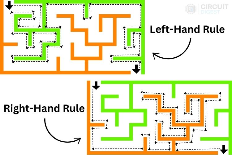
Without color differentiation (like orange and green), the maze can appear confusing. However, with clear paths highlighted, the navigation becomes straightforward. The Hand-on-Wall Rule algorithm is particularly useful for mazes with well-defined boundaries and continuous walls. It’s also ideal for robots with limited computational power or memory because it doesn’t require the robot to “remember” its path.
This approach mimics human behaviour when navigating dark or unknown spaces, where touching a wall provides direction and a sense of boundaries. Simple, effective, and ingenious!
Hope you have understood the core concept of this algorithm.
Working
In the GIF video below, you can see our robot navigating the maze using the Left-Hand Rule. This choice was made because, in this particular maze, applying the Right-Hand Rule would cause the robot to fail to reach the destination. Instead, it would endlessly loop around the track.
This limitation arises because the robot uses only three sensors. With more sensors, it would be possible to successfully navigate the maze using the Right-Hand Rule as well. However, for simplicity, we’ve chosen a design with just three sensors.
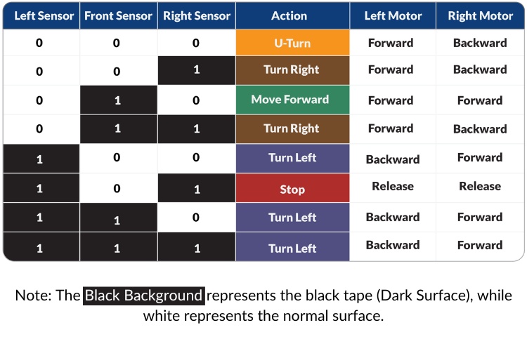
By keeping the sensor count to three, the robot requires only a small set of possible decisions, making the design and programming simpler and more accessible. Below, we’ll examine the truth table used in this robot to determine its behavior in various scenarios.
Now, lets start building the maze-solving Robot.
Components Required
For building a basic robot like this one, the components are quite flexible, and you can always scale up or down depending on your needs. Below are the components that I used in this project:
Arduino UNO - 1
Motor Shield of Arduino UNO - 1
IR Obstacle Detection sensor - 3
Two Wheel Drive Car Chassis - 1
Castor Wheel - 1
Bo Motors with appropriate wheel - 2
2s Lithium ion battery pack with BMS - 1
Connecting wires - Required
Screws, Nuts and Spacers - Required
Power Supply
While the power supply is flexible, it’s recommended to use a voltage source between 5V and 12V. A 9V battery would also work, but anything above 5V and below 12V is ideal for ensuring a steady power supply, especially for the motors. A higher voltage ensures that even if the motors draw significant power, the voltage drop won’t affect the Arduino's functionality (which could cause a restart).
Chassis
For the chassis, you can use a pre-built one or even opt for a cardboard chassis as a quick and low-cost alternative. The rest of the components are straightforward and commonly found in robotics kits.
With these components, you’re all set to start building your robot!
Maze Solving Robot Circuit Diagram
As we are using the Arduino motor shield, the circuit diagram becomes simpler because no special connection is needed between the motor shield and the Arduino UNO.

Above, you can see the circuit diagram of this maze-solving robot. It is self-explanatory, as we have provided a clear diagram with all the components marked. For added clarity, I am detailing the circuit below:
Since we are using the motor shield v1, we are limited to using the analog pins. Therefore, I am using A0, A1, and A2 as digital inputs for the left, front, and right sensors. These are the only pins exposed with individual pads, making soldering easier. The left and right motors are connected to the M1 and M2 motor outputs of the motor shield. While coding, you can check the motor direction. If any changes are needed, you can simply reverse the polarity of the motors.
Finally, we have the power supply, which is crucial. We are using an old 2S battery pack that provides an output voltage of 5.6V to 8.4V. This is more than enough for our project. If you choose a different motor, you might need to upgrade the power source.
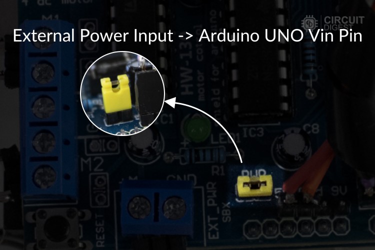
Additionally, you need to ensure the connection to the PWR pins of the motor driver module, as shown in the image above. These pins are responsible for connecting the battery input to the Vin pin of the Arduino. If this connection is missing, the Arduino UNO will not be powered.
Now that we have completed the circuit diagram explanation, let’s assemble the components according to the circuit diagram.
How to Make Maze Solving Robot?
For assembling the robot, if you are using the same components as I did, there will be no major hurdles in the process. However, if you are upgrading the components, there might be slight modifications required.
Another major area to focus on is the distance between each sensor and its position. Incorrect placement may result in improper movements. Additionally, some calibration will be necessary to ensure the robot runs properly.
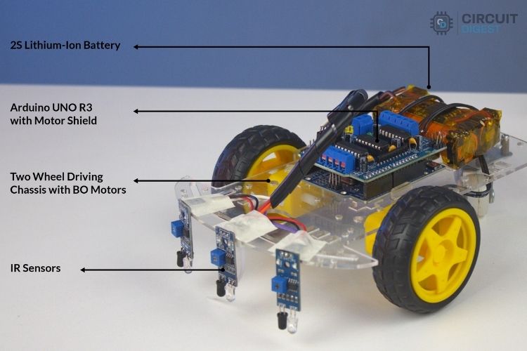
Above, you can see the assembled robot. The assembly process is straightforward and simple. The sensors are placed at the correct distance and verified through test runs. The sensors are connected using wires that are soldered to the motor driver module.
Maze Solving Robot Arduino Code
The maze-solving robot uses IR sensors to detect obstacles and employs a logical decision-making algorithm to navigate through a maze. The robot’s movement is controlled via DC motors interfaced with the Arduino Motor Shield V1. Below is a detailed breakdown of the code. Please note that this code is written to only find the exit of the maze it will not find the shortest path. But you can implement your own algorithm to find the shortest path if you are interested.
Libraries Used
AFMotor: This library controls the DC motors using the Arduino Motor Shield V1. It simplifies motor control with functions like setSpeed() and run().
#include <AFMotor.h>
AF_DCMotor motorA(1);
AF_DCMotor motorB(2);
Constants and variables
The IR sensors are assigned to analog pins A0, A1, and A2, which correspond to the left, front, and right sensors, respectively. Motor speeds and turning delays are also defined using constants for precise movement control.
const int leftSensor = A0;
const int frontSensor = A1;
const int rightSensor = A2;
const int forwardSpeed = 120;
const int TurningSpeed = 115;
const int turnDelay = 25;
const int uTurnDelay = 50;
Setup Function
The setup() function initializes the IR sensors as input devices to detect obstacles and sets up serial communication for debugging purposes.
void setup() {
  pinMode(leftSensor, INPUT);
  pinMode(frontSensor, INPUT);
  pinMode(rightSensor, INPUT);
  Serial.begin(9600);
}
Main Loop
The loop() function continuously reads data from the IR sensors and determines the robot’s movements using a switch-case logic. The sensor values (0 or 1) are combined into a binary representation to identify the current maze state (e.g., path available ahead, left, right, or no path). Based on the state, specific movement functions like moveForward(), turnLeft(), turnRight(), or uTurn() are called.
void loop() {
  int leftValue = digitalRead(leftSensor);
  int frontValue = digitalRead(frontSensor);
  int rightValue = digitalRead(rightSensor);
  int sensorState = (leftValue << 2) | (frontValue << 1) | rightValue;
  switch (sensorState) {
    case 0b000:uTurn();break;
    case 0b010:moveForward();break;
    case 0b111:turnLeft();break;
    case 0b100:turnLeft(); break;
    case 0b110:turnLeft();break;
    case 0b001:turnRight();break;
    case 0b011:turnRight();break;
    case 0b101:stopMotors();break;
    default:stopMotors();break;
  }
}
The complete code is provided at the end of this article, along with proper comments for better understanding.
Working of Maze Solving Robot
Once the code is uploaded to the assembled robot via the Arduino IDE, it’s time for testing. We have shown the complete working video of this maze-solving robot at the bottom of this page. But to understand what is happening let's look into it step-by-step.
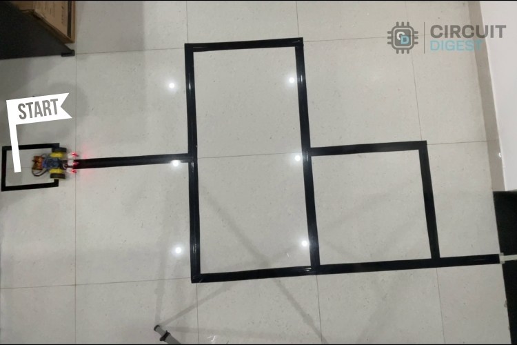
Step 1: Starting Position
- The robot starts at the entrance of the maze.
- It follows the Left-Hand Rule, meaning it will always keep its left sensor or side against the wall.
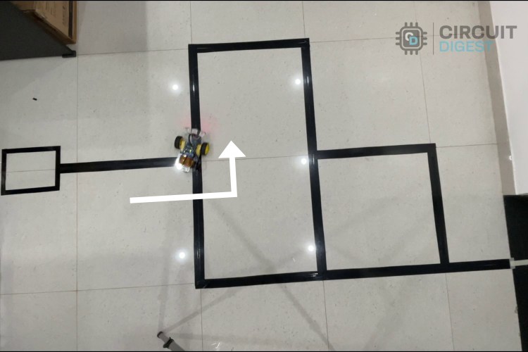
Step 2: Decision at Junction
- The first junction is a three-way intersection.
- As per the algorithm, the robot chooses the left path.
- If the junction offers only right and left paths, priority is always given to the left side.
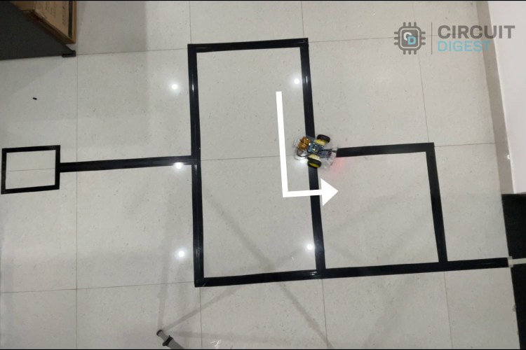
Step 3: Turning at Corners
- Next, the robot encounters two right-turn corners.
- Since both corners bend right, the robot moves right as expected.

Step 4: Decision at the Second Junction
- The next junction is another three-way intersection, but this time, the paths are straight and left.
- Since the Left-Hand Rule is followed, the robot turns left.
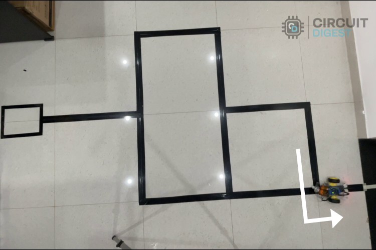
Step 5: Corner Turn
As like the previous corners the robot will turn in the corner in right direction.

Step 6: Final Movement
- The final junction resembles the first one, offering right and left paths.
- As expected, the robot chooses the left path, leading to the destination.
During the test, you'll notice that the robot does not travel in a perfectly straight line. This issue arises due to uneven speeds between the left and right motors. To address this, you can opt for the 4-wheel drive method for better balance and stability.
You can cross-check the robot's movement with the truth table provided in the code. The robot performs as expected, successfully navigating the maze.
GitHub Repo with Code and Circuit
The complete code for this maze-solving robot project is given at the bottom of this page. Further more here is also a link to our GitHub repo, where you'll find the source code for this project.


Conclusion and Future Improvements
If you have come this far, give yourself a pat on the back, for you have successfully built a basic maze-solving robot. But the best thing about this project is you can easily scale it and experiment with complex algorithms. Take a break and play with this robot build different maze patterns and see how your robot solves them. You will soon understand that this robot is not able to solve complex maze patterns and is definitely not the fastest maze solving robot out there. Now, you can wear your programming hat and code this robot to solve the maze faster and even find the shortest path, this will you will also be able to participate in maze-solving robot competitions where you can challenge yourself and your robot to solve complex mazes and compete with fellow engineers. Discover practical DIY electronic projects with complete circuit diagrams, code, and easy-to-follow instructions.
Projects Similar to maze-solving Robot
Previously we have built many interesting Arduino Projects. If you have successfully completed building this maze solving robot project here are a few other interesting projects that we have built previously. All the projects have detailed explanations on how to build along with code and circuit diagrams for you to learn and explore. You can also check our complete robotics projects if you want to explore more options.
")
Line Follower Robot using Arduino UNO: How to Build (Step-by-Step Guide)
This comprehensive guide demonstrates how to build a line follower robot using an Arduino UNO, covering hardware interfacing, sensor calibration, and motor control fundamentals.

Line Follower Robot using PIC Microcontroller
This tutorial explains how to build a line follower robot using the PIC16F877A microcontroller, detailing the working principles and construction process.

Line Follower Robot using 8051 Microcontroller
This guide provides instructions on designing a line follower robot with an 8051 microcontroller, including PCB layout and programming details.

Line Follower Robot using Raspberry Pi
Build a line-following robot powered by Raspberry Pi. This project integrates Python programming and GPIO control for precise navigation.

Raspberry Pi Pico based Line Follower Robot
This project involves creating a line-following robot using the Raspberry Pi Pico, demonstrating the robot's ability to track lines and reach destinations automatically.

How to Make Line Following Robot without using Microcontroller
This tutorial demonstrates how to design and build a basic line-following robot using IR sensors and a motor control circuit. A beginner-friendly project to explore robotics and circuit design concepts.

Line Follower Robot Using MSP430 LaunchPad
Learn how to create a line-following robot using Texas Instruments' MSP430 LaunchPad, IR sensors, and motor drivers. This project is perfect for understanding embedded systems and robotics with MSP430.
Complete Project Code
//Arduino Code for Maze Solving Robot Project
#include <AFMotor.h>  // Include the Adafruit Motor Shield library for motor control
// Motor Definitions
AF_DCMotor motorA(1);  // Motor A connected to terminal M1 on the motor shield
AF_DCMotor motorB(2);  // Motor B connected to terminal M2 on the motor shield
// Sensor Pin Definitions
const int leftSensor = A0;   // Left IR sensor pin
const int frontSensor = A1;  // Front IR sensor pin
const int rightSensor = A2;  // Right IR sensor pin
// Movement Parameters
const int forwardSpeed = 120;  // Speed for forward movement
const int TurningSpeed = 115;  // Speed for turning movements
const int turnDelay = 25;      // Delay for completing a turn
const int uTurnDelay = 50;    // Delay for completing a U-turn
void setup() {
 // Configure sensor pins as input
 pinMode(leftSensor, INPUT);
 pinMode(frontSensor, INPUT);
 pinMode(rightSensor, INPUT);
 // Initialize serial communication for debugging
 Serial.begin(9600);
}
void loop() {
 // Read sensor values (0 or 1)
 int leftValue = digitalRead(leftSensor);
 int frontValue = digitalRead(frontSensor);
 int rightValue = digitalRead(rightSensor);
 // Combine sensor states into a single value for switch-case logic
 int sensorState = (leftValue << 2) | (frontValue << 1) | rightValue;
 // Decision-making based on sensor states
 switch (sensorState) {
   case 0b000:  // No sensors detect a wall
     uTurn();   // Perform a U-turn
     Serial.println("Stop");
     break;
   case 0b010:       // Only the front sensor detects a wall
     moveForward();  // Move forward
     Serial.println("Move Forward");
     break;
   case 0b111:    // All sensors detect walls
     turnLeft();  // Turn left
     Serial.println("Turn Left");
     break;
   case 0b100:    // Only the left sensor detects a wall
     turnLeft();  // Turn left
     Serial.println("Turn Left");
     break;
   case 0b110:    // Front and left sensors detect walls
     turnLeft();  // Turn left
     Serial.println("Turn Left");
     break;
   case 0b001:     // Only the right sensor detects a wall
     turnRight();  // Turn right
     Serial.println("Turn Right");
     break;
   case 0b011:     // Front and right sensors detect walls
     turnRight();  // Turn right
     Serial.println("Turn Right");
     break;
   case 0b101:      // Left and right sensors detect walls
     stopMotors();  // Stop the motors
     Serial.println("Turn Left");
     break;
   default:         // Unknown sensor state
     stopMotors();  // Stop the motors as a safety measure
     Serial.println("Unknown State");
     break;
 }
}
// Function to move forward
void moveForward() {
 motorA.setSpeed(forwardSpeed);  // Set speed for motor A
 motorB.setSpeed(forwardSpeed);  // Set speed for motor B
 motorA.run(FORWARD);            // Move motor A forward
 motorB.run(FORWARD);            // Move motor B forward
}
// Function to turn left
void turnLeft() {
 motorA.setSpeed(TurningSpeed - 20);  // Reduce speed of motor A for smoother turn
 motorB.setSpeed(TurningSpeed);       // Set speed for motor B
 motorA.run(BACKWARD);                // Move motor A backward
 motorB.run(FORWARD);                 // Move motor B forward
 delay(turnDelay);                    // Delay to complete the turn
}
// Function to turn right
void turnRight() {
 motorA.setSpeed(TurningSpeed);       // Set speed for motor A
 motorB.setSpeed(TurningSpeed - 20);  // Reduce speed of motor B for smoother turn
 motorA.run(FORWARD);                 // Move motor A forward
 motorB.run(BACKWARD);                // Move motor B backward
 delay(turnDelay);                    // Delay to complete the turn
}
// Function to stop the motors
void stopMotors() {
 motorA.run(RELEASE);  // Release motor A
 motorB.run(RELEASE);  // Release motor B
}
// Function to perform a U-turn
void uTurn() {
 motorA.setSpeed(TurningSpeed);  // Set speed for motor A
 motorB.setSpeed(TurningSpeed);  // Set speed for motor B
 motorA.run(FORWARD);            // Move motor A forward
 motorB.run(BACKWARD);           // Move motor B backward
 delay(uTurnDelay);              // Delay to complete the U-turn
}
