
In this tutorial, we will learn about Real Time Clock (RTC) and its interfacing with the ESP32 and OLED display.
We will use the DS3231 RTC module to keep track of the correct time and display it on the SPI OLED by using ESP32 as our microcontroller. ESP32 is more than a microcontroller. It has a Wi-Fi and Bluetooth chip inside it and 39 GPIO pins. It supports all communication protocols like SPI, I2C, UART, etc. If you are new to ESP32, then first go through our Getting Started with ESP32 tutorial.
Table of Contents
- What is the DS3231 RTC Module with ESP32?
- Getting to know about OLED Displays
- DS3231 RTC Module Technical Specifications
- Material Required for ESP32 Real Time Clock using DS3231 Module
- DS3231 RTC Module Schematic and Circuit Connections
- Code Explanation:
- Technical Summary and GitHub Repository
- Frequently Asked Questions
- Conclusion: Mastering ESP32 DS3231 RTC Projects
- Projects Showcasing Real Time Using DS3231 Module
What is the DS3231 RTC Module with ESP32?
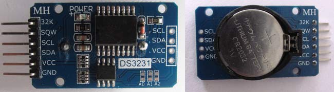
DS3231 is an RTC (Real Time Clock) module. It is used to maintain the date and time for most of the Electronics projects. This module has its own coin cell power supply, using which it maintains the date and time even when the main power is removed or the MCU has gone through a hard reset. So once we set the date and time in this module, it will keep track of it always. There are several types of RTC ICs available, like DS1307, DS3231, etc.
We have previously used DS3231 RTC with Arduino in below projects:
Note: When using this module for the first time, you have to set the date and time. You can also use the RTC IC DS1307, we have previously used DS1307 with Arduino.
Getting to know about OLED Displays
The term OLED stands for “Organic Light Emitting Diode.” It uses the same technology that is used in most of our televisions, but has fewer pixels compared to them. It is really fun to have these cool-looking display modules since it will make our projects look cool. We have covered a full Article on OLED displays and their types here.
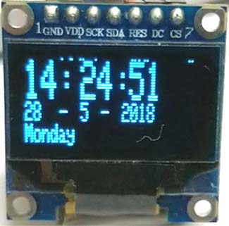
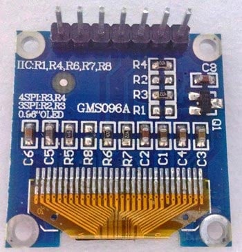
We are using a Monochrome 7-pin SSD1306 0.96” OLED display. The reason for choosing this display is that it can work on three different communication Protocols, such as the SPI 3 Wire mode, SPI four wire mode, and IIC mode. This tutorial will cover how to use the module in SPI 4-wire mode, as it is the fastest mode of communication and the default one.
The ESP32 real-time clock using DS3231 module pinout functions are explained in the table below.
Pin Number | Pin Name | Other Names | Usage |
1 | Gnd | Ground | Ground pin of the module |
2 | Vdd | Vcc, 5V | Power pin (3-5V tolerable) |
3 | SCK | D0, SCL, CLK | Acts as the clock pin. Used for both I2C and SPI |
4 | SDA | D1,MOSI | Data pin of the module. Used for both IIC and SPI |
5 | RES | RST, RESET | Resets the module (useful during SPI) |
6 | DC | A0 | Data Command pin. Used for SPI protocol |
7 | CS | Chip Select | Useful when more than one module is used under SPI protocol |
In this tutorial, we will simply operate the module in 4-Wire SPI mode; we will leave the rest for some other tutorial.
Arduino community has already given us a lot of Libraries that can be directly used to make this a lot simpler. I tried out a few libraries and found that the Adafruit_SSD1306 Library was very easy to use and had a handful of graphical options, hence we will use the same in this tutorial. But, if your project has a memory/speed constraint, try using the U8g Library as it works faster and occupies less program memory.
We have also interfaced OLED with Raspberry Pi and with Arduino.
DS3231 RTC Module Technical Specifications
The DS3231 RTC module with ESP32 offers the following key specifications for your real-time clock project:
- Operating Voltage: 3.3V to 5V (compatible with ESP32)
- Communication Protocol: I2C (SCL/SDA pins)
- Backup Power: CR2032 coin cell battery
- Accuracy: ±2ppm (approximately ±1 minute per year)
- Temperature Range: -40°C to +85°C
- Current Consumption: 1.5µA (battery backup mode)
We will use the DS3231 RTC module to keep track of the correct time and display it on the SPI OLED by using ESP32 as our microcontroller.
Material Required for ESP32 Real Time Clock using DS3231 Module
- ESP32
- DS3231 RTC module
- 7 pin 128×64 OLED display Module (SSD1306)
- Male-female wires
- Breadboard

DS3231 RTC Module Schematic and Circuit Connections
The circuit diagram to connect the RTC3231 to the ESP board is given below:

The RTC DS3231 IC uses the I2C mode of communication. It has SCL, SDA, Vcc, and GND pins coming out of it. Connection of the RTC module with the ESP32 is given below:
- SCL of RTC -> SCL of ESP32, i.e., Pin D22
- SDA of RTC -> SDA of ESP3,2 i.e., Pin D21
- GND of RTC -> GND of ESP32
- Vcc of RTC -> Vcc of ESP32
Here, we are using SPI mode to connect our 128×64 OLED display Module (SSD1306) to ESP32. So, it will use 7 pins. Connections with ESP32 are given as:
- CS(Chip select) pin of OLED -> PIN D5 of ESP32
- DC pin of OLED -> PIN D4 of ESP32
- RES pin of OLED -> PIN D2 of ESP32
- SDA pin of OLED -> PIN D23 i.e. MOSI of ESP32
- SCK pin of OLED -> PIN D18 i.e. SCK of ESP32
- Vdd of OLED -> Vcc of ESP32
- GND of OLED -> GND of ESP32
You need board files for your ESP32. Check in board manager drop-down menu of Arduino IDE for the ESP32 dev kit. If it is not there, follow the steps given in the link below:
https://circuitdigest.com/microcontroller-projects/getting-started-with-esp32-with-arduino-ide
You can also use ESP12 for this project. learn here to use ESP12.
Code Explanation:
Complete code for ESP32 is given at the end of the article. Here we are explaining a few important parts of the code.
We need several libraries to use in our code, which can be downloaded from the links below:
1. Adafruit_SSD1306 : https://github.com/adafruit/Adafruit_SSD1306
2. SPI : https://github.com/PaulStoffregen/SPI
3. Adafruit_GFX : https://github.com/adafruit/Adafruit-GFX-Library
4. RTClib : https://github.com/adafruit/RTClib
So we have included all the libraries
#include <SPI.h>   // for OLED display
#include <Wire.h>  // for I2C with RTC module
#include <Adafruit_GFX.h>
#include <Adafruit_SSD1306.h>  // for display graphics
#include "RTClib.h"       //to show time
Then define all the pins of OLED. You don't need to define pins for the RTC module because these pins are already defined in the WIRE library.
#define OLED_MOSI  23
#define OLED_CLK   18
#define OLED_DC    4
#define OLED_CS    5
#define OLED_RESET 2
Adafruit_SSD1306 display(OLED_MOSI, OLED_CLK, OLED_DC, OLED_RESET, OLED_CS);
In the setup function, we will call a function, rtc. Adjust (DateTime(__DATE__, __TIME__)), which will set the time according to our PC time.
void setup()
{
Serial.begin(9600);
if (! rtc.begin()) {
Serial.println("Couldn't find RTC");
while (1);
}
rtc.adjust(DateTime(__DATE__, __TIME__));
After that we call display functions to show on OLED.
display.begin(SSD1306_SWITCHCAPVCC);
display.clearDisplay();
display.setTextColor(WHITE);
//display.startscrollright(0x00, 0x0F); // You can uncomment this line to scroll your text on oled
display.setTextSize(2);
display.setCursor(0,5);
display.print("  Clock "); //This will Display Clock on OLED for 3 seconds
display.display();
delay(3000);
}
Then, finally, in the loop function, we will store our time in the DateTime now pre-defined variable and display the time using display functions like setTextSize, setCursor, etc. Set these according to your needs and use the display. println function to show on OLED.
void loop()
{
DateTime now = rtc.now();
display.clearDisplay();
display.setTextSize(2);
display.setCursor(75,0);
display.println(now.second(), DEC);
So this is how you can display time on OLED using ESP32, and as you know, ESP is known for its IoT capabilities, so you can use this to publish the time on the internet. In the next article, we will show you how to display Internet Time on ESP without using any RTC Module.
Technical Summary and GitHub Repository
An outline of the project's components, functionality, and working logic is given in this section. Along with important technical details and circuit behavior, it illustrates the interactions between various modules. You'll learn about the system's data flow and code structure through GitHub access.


Frequently Asked Questions
⇥ How does one use I2C to interface the DS3231 RTC module with the ESP32?
Install Vcc to 3.3V/5V, SDA to GPIO21, SCL to GPIO22, and GND to GND.
⇥ In the ESP32 with DS3231 RTC project, which I2C library is utilized?
Adafruit's RTClib library is used.
⇥ How can you use an ESP32 to show real-time clock data on a 16x2 LCD?
Print the time using an I2C LCD, an I2C connection, and the LiquidCrystal_I2C library.
⇥ In the case of a power failure, how does the DS3231 module keep time?
The clock is maintained by an internal battery backup (CR2032).
Conclusion: Mastering ESP32 DS3231 RTC Projects
Everything required to successfully construct an ESP32 real-time clock with the DS3231 module was covered in this extensive tutorial. We examined the schematic of the DS3231 RTC module, the full ESP32 DS3231 RTC wiring diagram, and the correct pinout configurations. The DS3231 RTC module with ESP32 combination is perfect for IoT projects, data loggers, and automation systems that need precise time management because it offers accurate timekeeping with battery backup.
Projects Showcasing Real Time Using DS3231 Module
Explore a range of projects that utilize the DS3231 Real-Time Clock (RTC) module for precise timekeeping. Ideal for applications such as digital clocks, data loggers, time-triggered automation, and smart scheduling systems.
 with PIC Microcontroller: Digital Clock")
Interfacing RTC Module (DS3231) with PIC Microcontroller: Digital Clock
So here we are interfacing an RTC module with a PIC Microcontroller and displaying the time and date on the 16x2 LCD. This project can also be used as Digital Clock.

Internet Clock using ESP32 and OLED Display
To minimize hardware requirements, we will make an Internet clock without using an RTC module. This is more accurate compared to the RTC clock. ESP32 is a Wi-Fi module and can be easily connected to the internet, so we will use NTP (Network Time Protocol) and UDP (User Datagram Protocol) to fetch Time from the internet using Wi-Fi.
 with MSP430: Digital Clock")
Interfacing RTC module (DS3231) with MSP430: Digital Clock
In this tutorial, we will make a Digital Clock by interfacing the RTC module DS3231 with the MSP430 and display the time and date on a 16x2 LCD.
Complete Project Code
#include <SPI.h>
#include <Wire.h>
#include <Adafruit_GFX.h>
#include <Adafruit_SSD1306.h>
#include "RTClib.h"
RTC_DS3231 rtc;
char daysOfTheWeek[7][12] = {"Sunday", "Monday", "Tuesday", "Wednesday", "Thursday", "Friday", "Saturday"};
#define OLED_MOSI  23
#define OLED_CLK   18
#define OLED_DC    4
#define OLED_CS    5
#define OLED_RESET 2
Adafruit_SSD1306 display(OLED_MOSI, OLED_CLK, OLED_DC, OLED_RESET, OLED_CS);
void setup()
{
Serial.begin(9600);
if (! rtc.begin()) {
Serial.println("Couldn't find RTC");
while (1);
}
rtc.adjust(DateTime(__DATE__, __TIME__));
display.begin(SSD1306_SWITCHCAPVCC);
display.clearDisplay();
display.setTextColor(WHITE);
//display.startscrollright(0x00, 0x0F);
display.setTextSize(2);
display.setCursor(0,5);
display.print("  Clock ");
display.display();
delay(3000);
}
void loop()
{
DateTime now = rtc.now();
display.clearDisplay();
display.setTextSize(2);
display.setCursor(75,0);
display.println(now.second(), DEC);
display.setTextSize(2);
display.setCursor(25,0);
display.println(":");
display.setTextSize(2);
display.setCursor(65,0);
display.println(":");
display.setTextSize(2);
display.setCursor(40,0);
display.println(now.minute(), DEC);
display.setTextSize(2);
display.setCursor(0,0);
display.println(now.hour(), DEC);
display.setTextSize(1);
display.setCursor(0,15);
display.println(now.day(), DEC);
display.print(daysOfTheWeek[now.dayOfTheWeek()]);
display.setTextSize(1);
display.setCursor(25,15);
display.println("-");
display.setTextSize(1);
display.setCursor(40,15);
display.println(now.month(), DEC);
display.setTextSize(1);
display.setCursor(55,15);
display.println("-");
display.setTextSize(1);
display.setCursor(70,15);
display.println(now.year(), DEC);
display.display();
}
Comments
First a remark related to Mr. Duaz comment dated may-27. 2019:
comment =
I can understand the use of an external RTC, as I noticed that the ESP32-RTC is not that accurate. (I believe this is already generally known.)
I wrote a little sketch, writing 3 constanly same data-points to MySQL at 30 seconds intervals. I let it ran for 24 hrs and found that the actual interval is on average 32.5 sec. (Ranging from 31 to 36 sec.) (Part of this might be due to work the Synology-NAS was doing.)
Regards,
Leo
Hello,
This is actually not a comment, but more a question.
First of all: I am a noob. I can do quite lot, but some things are beyond me.
I recently started working with ESP32.
I want to replace my Arduino Mega with an ESP32, doing the same work the Arduino is doing now.
The Arduino measures my Elec. Power and Gas consumption and posts this in MySQL every 5th minute. Data sent is: avg-W, hourly Wh, daily kWh, avg-dm3, hourly dm3 and daily m3. Measurements are reset at midnight. For this purpose I have a DS3231 attached to the Arduino.
I can get the ESP32 working with DS3231, time/date-wise. But I can not set 'alarms' for resetting. Because I have now clue how to set alarms, in combination with ESP32. (I can with Arduino.)
When I use the Arduino-script (or actually arduino libraries), I get all sort of fault-reports. It seems like that the libraries I use are not compatible with ESP32.(And I have used/downloaded a lot different ones.)
The only DS3231 librarie which seems to work is RTClib.h (made by JeeLab?), but I have no clue how to set the alartms. I have Googled a lot, but no succes.
Can one of you experts help or point me to the right librarie?
With best regards,
Leo
Greetings
The oled clock is great, but where do the leading '0' on the hours min and sec go in the source code, also the seperation of the day date and year need adjustment.
Keep up the good work.
Fritzing picture shows....
SCL to D21 and SDA to D22
Just below that, the text says....
SCL of RTC -> SCL of ESP32 i.e. Pin D22
SDA of RTC -> SDA of ESP32 i.e. Pin D21
The text is correct. The Fritzing image is wrong.

the esp32 has an inbuilt RTC, so why would you want to use an external one?