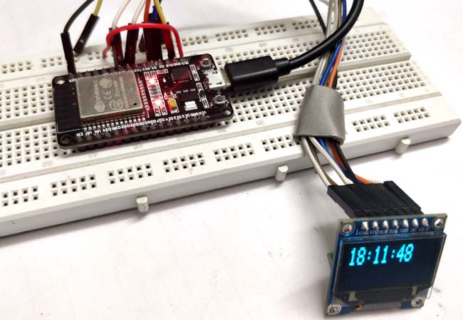
In the previous tutorial, we have made RTC clock using DS3231 and ESP32. To minimize hardware requirements we will make Internet clock without using RTC module. This is more accurate as compare to RTC clock. ESP32 is a Wi-Fi module and can be easily connected to the internet so we will use NTP (Network Time Protocol) and UDP (User Datagram Protocol) to fetch Time from the internet using Wi-Fi. This Internet clock can be very useful while building IoT Projects.
What is NTP??
Network Time Protocol (NTP) is a networking protocol used for synchronization of time between systems a0nd Data networks. The NTP framework depends on Internet Time servers. NTP has algorithms to precisely adjust the time of day. NTP servers have software which send the clock's time of day to client computers using UDPport 123. So here in this project, we are getting time from NTP server using ESP32 and showing it on OLED display.

Materials Required:
- ESP32
- 128*64 OLED display
- Breadboard
- Male-female wires
Circuit Diagram:
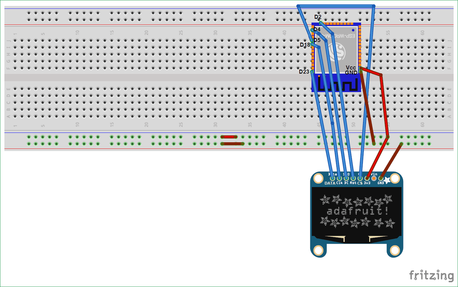
Here, we are using SPI mode to connect our 128×64 OLED display Module (SSD1306) to ESP32. So, it will use 7 pins. Connections with ESP32 are given as:
- CS(Chip select) pin of OLED -> PIN D5 of ESP32
- DC pin of OLED -> PIN D4 of ESP32
- RES pin of OLED -> PIN D2 of ESP32
- SDA pin of OLED -> PIN D23 i.e. MOSI of ESP32
- SCK pin of OLED -> PIN D18 i.e. SCK of ESP32
- Vdd of OLED -> Vcc of ESP32
- GND of OLED -> GND of ESP32
You need board files for your ESP32. Check-in board manager drop down menu of Arduino IDE for ESP32 dev kit. If it is not there follow the steps given in the link below:
https://circuitdigest.com/microcontroller-projects/getting-started-with-esp32-with-arduino-ide
You can also use ESP12 for this project, learn here to use ESP12.
We will use Arduino IDE to write our program as explained in above article.
Code Explanation:
The complete code for ESP32 Internet Clock is given at the end of the article. Here we are explaining few important parts of code.
We need several libraries to use in our code which can be downloaded from the below links:
1. Adafruit_SSD1306: https://github.com/adafruit/Adafruit_SSD1306
2. SPI: https://github.com/PaulStoffregen/SPI
3. Adafruit_GFX: https://github.com/adafruit/Adafruit-GFX-Library
4. NTPClient: https://github.com/arduino-libraries/NTPClient
5.WiFiUdp: https://github.com/esp8266/Arduino/tree/master/libraries/ESP8266WiFi
So we have included all the libraries and defined variable for entering Wi-Fi name and password.
#include <WiFi.h>
#include <SPI.h>
#include <Adafruit_GFX.h>
#include <Adafruit_SSD1306.h>
#include <NTPClient.h>
#include <WiFiUdp.h>

const char* ssid     = "*******";                          //WiFi Name
const char* password = "*********";                   // WiFi Password
Here NTPClient.h library is used to connect with the time server. It takes time from a NTP server and keep it in sync. And Hhre WiFiUdp.h library is used to send and receive UDP messages. UDP is a protocol which sends and receive short messages from our system to NTP server.
So to get the time from Internet, we have to define three variables in our program for NTP.
NTP_OFFSET which is the time zone of your country i.e. for India it is +5:30 hour. So it is 19800 in seconds.
NTP_INTERVAL which is time interval taken by NTP to update time. It is 60-64 seconds.
NTP_ADDRESS is the NTP server of your country. For India you can use “in.pool.ntp.org”.
#define NTP_OFFSET  19800 // In seconds
#define NTP_INTERVAL 60 * 1000    // In miliseconds
#define NTP_ADDRESS  "1.asia.pool.ntp.org"

WiFiUDP ntpUDP;
NTPClient timeClient(ntpUDP, NTP_ADDRESS, NTP_OFFSET, NTP_INTERVAL);
In setup Function, initialise Wi-Fi settings to connect with internet.
void setup()
{
display.begin();
Serial.begin(9600);
Serial.println();
Serial.println();
Serial.print("Connecting to ");
Serial.println(ssid);
WiFi.begin(ssid, password);
while (WiFi.status() != WL_CONNECTED)
{
delay(500);
Serial.print(".");
}
Serial.println("");
Serial.println("WiFi connected.");
Serial.println("IP address: ");
Serial.println(WiFi.localIP());
timeClient.begin();
Then initialize display functions to show time on OLED.
display.begin(SSD1306_SWITCHCAPVCC);
In loop function, we have used timeClient.update(), this function take updated time from NTP in form of string and stores it in formattedTime variable. Then display it on OLED using display.println() function.
void loop()
{
timeClient.update();
String formattedTime = timeClient.getFormattedTime();
display.clearDisplay();
display.setTextSize(2);                         // set these parameters according to your need..
display.setCursor(0, 0);
display.println(formattedTime);
Full program is given below. Now finally program ESP32 with Arduino IDE and your Internet Clock is ready to show time.
Complete Project Code
#include <WiFi.h>
#include <SPI.h>
#include <Adafruit_GFX.h>
#include <Adafruit_SSD1306.h>
#include <NTPClient.h>
#include <WiFiUdp.h>
const char* ssid     = "*******";
const char* password = "*********";

#define NTP_OFFSET  19800 // In seconds
#define NTP_INTERVAL 60 * 1000    // In miliseconds
#define NTP_ADDRESS  "1.asia.pool.ntp.org"
WiFiUDP ntpUDP;
NTPClient timeClient(ntpUDP, NTP_ADDRESS, NTP_OFFSET, NTP_INTERVAL);
#define OLED_MOSI  23
#define OLED_CLK   18
#define OLED_DC    4
#define OLED_CS    5
#define OLED_RESET 2
Adafruit_SSD1306 display(OLED_MOSI, OLED_CLK, OLED_DC, OLED_RESET, OLED_CS);

void setup()
{
display.begin();
Serial.begin(9600);
Serial.println();
Serial.println();
Serial.print("Connecting to ");
Serial.println(ssid);
WiFi.begin(ssid, password);
while (WiFi.status() != WL_CONNECTED)
{
delay(500);
Serial.print(".");
}
Serial.println("");
Serial.println("WiFi connected.");
Serial.println("IP address: ");
Serial.println(WiFi.localIP());
timeClient.begin();
display.begin(SSD1306_SWITCHCAPVCC);
display.clearDisplay();
display.setTextColor(WHITE);
//display.startscrollright(0x00, 0x0F);
display.setTextSize(2);
//display.setCursor(0,0);
//display.print("  Internet ");
//display.println("  Clock ");
//display.display();
//delay(3000);
}
void loop()
{
timeClient.update();
String formattedTime = timeClient.getFormattedTime();

// Serial.println(formattedTime);
display.clearDisplay();
display.setTextSize(2);
display.setCursor(0, 0);
display.println(formattedTime);
display.display();   // write the buffer to the display
delay(10);
delay(100);
}


