

The internet has reached almost every pocket through smartphones. It is estimated that approximately 3.2 billion people use the internet; however, a surprising 8.4 billion devices also utilise the internet. ESP32 Arduino IDE is emerging as the most popular development combination for IoT projects. Electronic devices are connected to the internet more than twice the population who use the internet, and it is making the things around us smarter every day. The major reason is the boom of the Internet of Things, which is commonly known as IoT. It is also estimated that by the end of 2020, we will have 20.4 billion devices connected to the internet. So it’s time to gear up and roll up our sleeves to work with IOT projects if we want to keep up with this development. I'll guide you through the complete process to connect ESP32 to Arduino IDE and start programming within 30 minutes.
The ESP32 WROOM-32 Arduino IDE combination offers unmatched flexibility for both beginners and professionals. Espressif Systems launched the ESP8266-01 long back, which opened doors to many hobbyists to get into the world of IoT. Since then, the community has been developing strongly, and many products have hit the market. Now, the launch of the ESP32 Espressif has taken things to a new level. This tiny, cheap 8$ module is a dual-core 32-bit CPU with built-in Wi-Fi and dual-mode Bluetooth with a sufficient amount of 30 I/O pins for all basic electronics projects. All these features are very easy to use, since they can be programmed directly from the Arduino IDE. Exciting enough. You'll learn how to install ESP32 in Arduino IDE, configure the development environment, and upload your first program successfully.
In this comprehensive guide, you'll learn everything you need to know to start programming ESP32 using the Arduino IDE in traditional ways. Configuring the Arduino ESP32 board can seem complicated at first, but it will be an easy process when using the method below to show you exactly how. By the time you finish this article, you will be able to develop amazing ESP32 projects using Arduino syntax and libraries.
ESP32 Blink LED using Arduino IDE - Quick Overview
Build Time: 30-60 minutes | Cost: $8-15 | Difficulty: Beginner
What You'll Learn: ESP32 setup, Arduino IDE integration, GPIO pin control, Basic LED programming
Applications: IoT prototyping, Basic circuit testing, Microcontroller introduction, LED-based indicators
Table of Contents
Why Choose ESP32 Arduino IDE?
There are several strong reasons for choosing to connect ESP32 to the Arduino IDE. Typical Arduino boards don't have wireless connectivity, and developers must resort to using additional shields or modules. ESP32 WROOM-32 is a fully integrated Wi-Fi and Bluetooth system - lowering the complexity of your project even further.
You are running the Arduino ecosystem plus unique ESP32 features when you program ESP32 with Arduino IDE. The Arduino ESP32 board itself supports thousands of libraries, examples from the community, and generic coding paradigms that will fast-track development cycles.
» Dual-core processing power - 240MHz CPU means you can run your complex applications on it.
» Arduino ESP32 board is supported - You can use familiar Arduino syntax.
» A large community of people to support your work - There are thousands of libraries, and example.
» Economical solution - A professional tool for the price of a hobbyist one.
Materials Required for ESP32 Arduino IDE Setup
- ESP32 Module
- Arduino IDE
- Programming cable (micro USB cable)
- The soul stone from MCU (just kidding)
ESP32 WROOM-32 Arduino IDE Compatibility and Hardware Overview
Before learning to install ESP32 in Arduino IDE, understanding the hardware architecture is crucial. It is slightly bigger than the ESP8266-01 module and is breadboard-friendly since most of the pin headers are broken out as I/O pins facing each other, which is a great thing. Let’s break the board into small parts to know the purpose of each segment
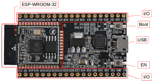
As you can see, the heart of the module is the ESP-WROOM-32, which is a 32-bit microprocessor. It also has a couple of buttons and LEDs, when you connect the ESP32 Arduino IDE, which are explained below, with key hardware components, including:
Micro-USB jack: The micro USB jack is used to connect the ESP32 to our computer through a USB cable. It is used to program ESP32 with Arduino IDE as well, and can also be used for serial debugging, as it supports serial communication.
EN Button: The EN button is the reset button of the ESP32 WROOM-32. Pressing this button will reset the code running on the Arduino ESP32 board.
Boot Button: This button is used to upload the program when you connect ESP32 to Arduino IDE. It has to be pressed after clicking on the upload icon on the Arduino IDE. When the Boot button is pressed along with the EN button, ESP enters firmware uploading mode. Do not play with this mode unless you know what you are doing.
Red LED: The Red LED on the board is used to indicate the power supply. It glows red when the board is powered, and provides visual feedback for your ESP32 Arduino IDE programs.
Blue LED: The Blue LED on the board is connected to the GPIO pin. It can be turned on or off through programming. In some Chinese cloned boards like mine, this might also be in red.
I/O pins: This is where major development has taken place. Unlike ESP8266, on ESP32, we can access all the I/O pins of the module through the breakout pins. The ESP32 WROOM-32 Arduino IDE configuration provides access to most GPIO pins. These pins are capable of Digital Read/Write, Analog Read/Write, PWM, IIC, SPI, DAC and much more. We will get more into that later. But if you are interested, you can learn through the pin description in the ESP32 Datasheet.
ESP-WROOM-32: This is the heart of the ESP32 module. It is a 32-bit microprocessor developed by Espressif Systems. If you are more of a technical person, you can read through the ESP-WROOM-32 Datasheet. I have also listed a few important parameters below.
ESP32 | |
Specification | Value |
Number of cores | 2 |
Architecture | 32 bit |
CPU Frequency |
|
Wi-Fi | YES |
Bluetooth | YES |
RAM | 512 KB |
FLASH | 16 MB |
GPIO Pins | 36 |
Communication Protocols | SPI, IIC, I2S, UART, CAN |
ADC channels | 18 channels |
ADC Resolution | 12-bit |
DAC channels | 2 |
DAC Resolution | 8-bit |
For now, this is all the information that we need to know about the hardware. We will cover more in-depth as we move through different projects using the ESP32.
ESP32 vs Arduino vs Raspberry Pi Comparison
Feature | ESP32 WROOM-32 | Arduino Uno R3 | Raspberry Pi 4 |
|---|---|---|---|
Processor | Dual-core 32-bit @ 240MHz | Single-core 8-bit @ 16MHz | Quad-core 64-bit @ 1.5GHz |
RAM | 512 KB SRAM | 2 KB SRAM | 1GB - 8GB LPDDR4 |
Flash Storage | 4MB - 16MB | 32 KB | MicroSD (16GB+) |
GPIO Pins | 36 (30 usable) | 14 digital + 6 analog | 40 GPIO pins |
Wi-Fi | 802.11 b/g/n built-in | No (requires shield) | 802.11ac built-in |
Bluetooth | BLE + Classic | No | 5.0 BLE |
Power Consumption | 20mA - 240mA | 20mA - 50mA | 600mA - 1.25A |
Price Range | $3 - $8 | $20 - $25 | $35 - $75 |
Arduino IDE Support | Full compatibility | Native support | Not compatible |
Real-time Processing | Excellent | Good | Limited |
How to Install ESP32 in Arduino IDE: Step-by-Step Process
As mentioned earlier in this tutorial, we are going to program esp32 with Arduino IDE since it has a strong community support. But you can also program the ESP32 using other software by the ESP Toolchain. This one-time setup enables seamless Arduino ESP32 board development for all future projects. Whenever we try to install the ESP32 in the Arduino IDE, we need to pay close attention to the details. The ESP32 WROOM-32 Arduino IDE integration, unlike Arduino IDE-supported Arduino boards, needs further steps to set up board definitions and toolchain components.
Also, this tutorial will only explain how to get started with the Windows platform. If you are from other platforms, follow the links below
- Instructions for Mac
- Instructions for Debian/Ubuntu Linux
- Instructions for Fedora
- Instructions for openSUSE
Preparing Arduino IDE for ESP32 WROOM-32 Integration
STEP 1⇒ Now, let’s get started. The first step would be to download and install the Arduino IDE. This can be done easily by following the link https://www.arduino.cc/en/Main/Software and downloading the IDE for free. Ensure you're using version 1.8.0 or newer for optimal ESP32 Arduino IDE compatibility.
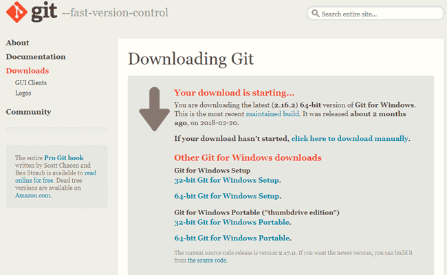
STEP 2 ⇒ Next, proceed to this link to download GIT, and a download will begin automatically named “Git-2.16.2”. Wait for the download to complete. The ESP32 WROOM-32 Arduino IDE support files are distributed through GitHub, making Git installation mandatory for the setup process.
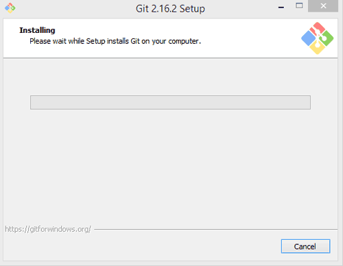
STEP 3 ⇒ Once the download is complete, open the exe file to install GIT on your computer. Just click on Next for all the options without changing anything to begin the ESP32 Arduino IDE installation process.
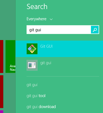
STEP 4⇒ Search for the name “GIT GUI” to find the one that we just installed. Do not open GIT bash. By default, GIT GUI will be installed on the C drive under the Program Files directory. This downloads all necessary files to connect ESP32 to Arduino IDE effectively.
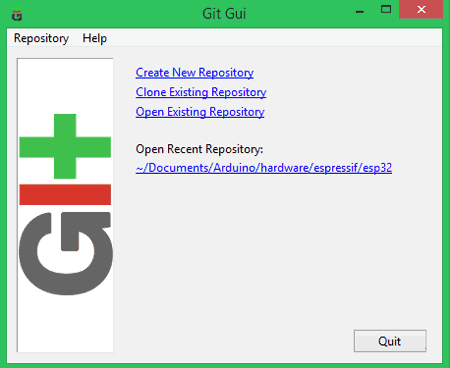
STEP 5⇒ Launch the GIT GUI application. Then select “Clone existing repository”. Ensure to Install ESP32 in Arduino IDE
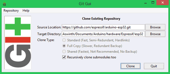
STEP 6⇒ The following window will appear, in which you should do the following.
Under Source Location, paste: https://github.com/espressif/arduino-esp32.git
Under Target Directory Paste: [ARDUINO_SKETCHBOOK_DIR]/hardware/espressif/esp32
[ARDUINO_SKETCHBOOK_DIR] can be found by clicking on File -> Preferences on the Arduino IDE
Mine is C:/Users/Aswinth/Documents/Arduino, so my target directory will be C:/Users/Aswinth/Documents/Arduino/hardware/Espressif/esp32. Once pasted, my screen looked as shown below
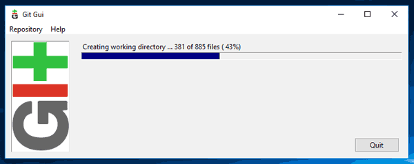
STEP 7⇒ After ensuring the correct location paths, click on clone, and you will get the following screen. This downloads all necessary files to connect ESP32 to Arduino IDE effectively.
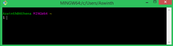
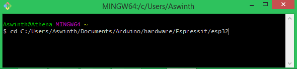
STEP 8⇒ Now again search for “Git Bash” and open it. You will get the following window.
STEP 9⇒ Now type “cd” and then paste your Target directory again here. Mine looked like this after pasting. Then hit enter.
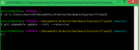
STEP 10⇒ Now paste git submodule update --init –recursive and hit enter to get the following screen to download additional dependencies required for ESP32 WROOM-32 Arduino IDE functionality.
STEP 11⇒ Now open “[ARDUINO_SKETCHBOOK_DIR]/hardware/espressif/esp32/tools” and then double click on the file get.exe. Wait for the process to finish. Once completed, you should see the following files in the directory

That is it, now our Arduino IDE is prepared to work with ESP32. Let’s go ahead and check if it is working.
Connect ESP32 to Arduino IDE: Configuration and Testing
STEP 1⇒ Connect your ESP32 board to your computer through the micro-USB cable. Make sure the red LED goes high on the module to ensure a power supply.
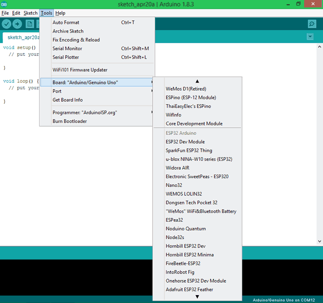
STEP 2⇒ Start the Arduino IDE and navigate to Tools -> Boards and select the ESP32Dev board as shown below. This selection configures the IDE for ESP32 WROOM-32 Arduino IDE programming.
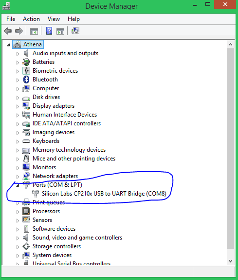
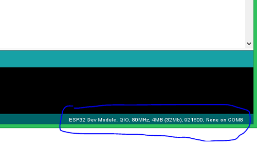
STEP 3⇒ Open Device Manager and check to which COM port your ESP32 Arduino IDE is connected. Mine is connected to COM 8 as shown below
STEP 4⇒ Go back to Arduino IDE and under Tools -> Port, Successful port selection enables communication between your computer and the ESP32 WROOM-32 for programming and debugging.
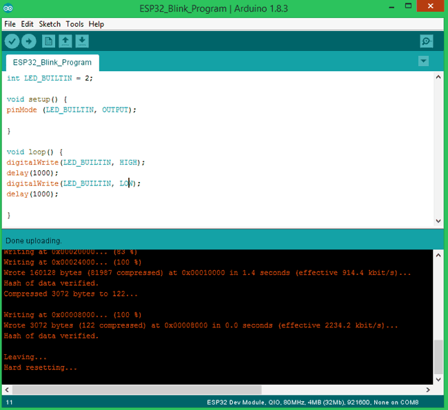
STEP 5⇒ Let’s upload the Blink Program to check if we can program our ESP32 module. This program should blink the LED at an interval of 1 second.
int LED_BUILTIN = 2;
void setup() {
pinMode (LED_BUILTIN, OUTPUT);
}
void loop() {
digitalWrite(LED_BUILTIN, HIGH);
delay(1000);
digitalWrite(LED_BUILTIN, LOW);
delay(1000);
}
The program is very similar to the Arduino blink code, hence I am not explaining it in detail. But one change is that, here in ESP32, the LED on board is connected to PIN 2, while for Arduino it will be connected to PIN 13. This enhanced blink program demonstrates key differences when you program ESP32 with Arduino IDE compared to traditional Arduino programming.
STEP 6⇒ To upload the code, just click on upload, and you should see the Arduino console displaying the following if everything works as expected.
Note: For some modules, you might have to hold the Boot button during uploading to avoid an error.
That is it, we have successfully uploaded our first code to our ESP32 board. My module with its LED blinking is shown below
ESP32 Arduino IDE Connection Problems Troubleshooting
Even seasoned developers face issues learning how to install the ESP32 Arduino IDE. Some common problems after installation have been driver problems, port recognition issues, or upload failures. You can expect this troubleshooting guide to tell you how to solve 95% of the problems during the setup.
Resolving ESP32 WROOM-32 Arduino IDE Communication Issues
Issue 1: The ESP32 Board Not Detected
At the first meeting of ESP32 with Arduino IDE is attached to the appropriate port. Ensure that the USB drivers are installed for your particular board USB-to-serial converter (be it CP2102, CH340G, or FTDI).
Issue 2: Upload Timeout Errors
If you have trouble during code upload with your Arduino ESP32 board through "Connecting...." timeout error, you should try lowering the upload speed to 115200 baud or manually put the ESP32 into boot mode using the BOOT button sequence.
Issue 3: Compilation Errors
Compilation errors when program ESP32 with Arduino IDE usually point to an incomplete installation of the toolchain. Run get.exe again and make sure all imperative ESP32 board files are installed.
Best Practices for ESP32 Arduino IDE Development
To complete any ESP32 WROOM-32 project in Arduino IDE, a programmer must understand the pertinent considerations related to the platform. The development of an ESP32 seems less traditional than that of an Arduino. Programming the ESP32 involves dual-core processing, wireless stack management, and sophisticated light-weight peripheral control that will seem foreign to the typical Arduino developer.
Memory management must be considered diligently when you program ESP32 with Arduino IDE. The ESP32 has 512KB of RAM. This is sufficient to develop rather complex applications; however, this will bring certain disadvantages due to dynamic allocation and stack size limitations. Another point for consideration is the use of any Serial.print() / Serial.println() statements when running the final production code. Using these statements will severely hamper performance due to complicated buffering.
Pin assignment is also far different on Arduino and ESP32 Arduino IDE projects than on normal Arduino projects. Since GPIO pin assignment will not make a difference in traditional Arduino boards, always double-check the ESP32 pinout diagram before building any circuit. With the ESP32, some GPIO pins have alternate functions and/or pins, or unusable GPIO pins.
Technical summary and GitHub Repository
The Technical Summary describes all aspects of the project components, design principles, and process functions in an explicit, straightforward manner. The Technical Summary is a snapshot of the system's workflow and innovations therein. Complementing the Technical Summary is the GitHub Repository, where you have access to source codes, schematics, full documentation, and an easy means of replicating or modifying the project.


Frequently Asked Questions on ESP32 Arduino IDE
⇥ Question 1: How do I install the ESP32 onto the Arduino IDE?
Thus, you have to download Git, clone the ESP32 Arduino repository inside your Arduino hardware folder, git submodule update, run the get.exe in the tools directory, and select ESP32 Dev Module from Tools>Board.
⇥ Question 2: Can we program ESP32 under the Arduino IDE?
YES, it should run, and it will run, going on the first installation of the ESP32 boards package because the ESP32 is also supported on the Arduino IDE. You can code ESP32 WROOM-32 modules to make it as easy as you code in Arduino Syntax, libraries, and functions.
⇥ Question 3: Main differences between the ESP32 and Arduino boards?
ESP32 has dual-core 32 Bit processing, Wifi/Bluetooth built in!, 36 GPIO Pins and 512KB of Flash! The Arduino Uno is a single-core 8 Bit processor, no wireless options, 14 digital pins and 2 KB of Flash Ram!
⇥ Question 4: Why is my ESP32 not being detected by the Arduino IDE?
USB cable should be a data cable; if drivers are ditched, check them out. Check that you are selecting the right serial port, and also ensure that your ESP32 is in programming mode and that you've installed the ESP32 board package for the Arduino IDE.
⇥ Question 5: What ESP32 board in Arduino IDE should I select?
If you are using a different ESP32 board than the default, you will select "ESP32 Dev Module" when it prompts "Select Board". If using a specific ESP32 variant, you will select "ESP32-WROOM-DA Module". If using a NodeMCU ESP32 board, you will select "NodeMCU-32S". When selecting an ESP32 board, make sure that you select the one which fits your board's specifications.
⇥ Question 6: Can I use Arduino libraries in the ESP32?
Most of the Arduino libraries should work with the ESP32; however, some libraries require their ESP32 versions in some cases. You can also use the libraries of the ESP32 Arduino Core, provided you have the original Arduino libraries, to pick up on some better features of the ESP32: Wi-Fi and Bluetooth.
⇥ Question 7: How do I upload to the ESP32 via the Arduino IDE?
Connect to the ESP32 via USB. In the Tools Menu, select the appropriate board and port, and click upload. Some boards need you to hold the BOOT button down while uploading. After uploading, you can verify that the upload was successful in the Console's output.
Conclusion: Mastering ESP32 Arduino IDE Development
Learning to connect ESP32 to Arduino IDE opens up unlimited opportunities for IoT development. The ESP32 WROOM-32 Arduino IDE combination offers professional-type features for hobbyist prices. As such, it is ideal for learning about microcontrollers and developing proof-of-concept projects and commercial products.
This complete guide has introduced the details of how to install ESP32 in Arduino IDE, how to set up your development environment, and how to get started with programming ESP32 with the Arduino IDE. The Arduino ESP32 board ecosystem is still developing, with new libraries and examples being frequently added by the extremely vibrant community of developers.
Original examples are a good place to start, and then begin to experiment with Wi-Fi, and then explore increasingly sophisticated features such as Bluetooth communication, deep sleep modes, and multi-tasking capabilities. Your journey with ESP32 Arduino IDE development is just at the beginning; the potential is almost endless!
You can go ahead and try the other example programs, which are available at File -> Example -> ESP32, to work with other functionalities of the ESP32. If you have had any problem in getting this work, feel free to post the query in the comments section below. You can also use the Forum for getting technical help.
Related ESP32 Projects
Develop a deeper understanding of the ESP32’s versatility by exploring these hands-on projects that extend beyond basic setup. From Bluetooth connectivity to real-time web-based monitoring and full-fledged weather stations, these examples showcase how the ESP32 can power a wide range of IoT applications.

In this tutorial we will build a BLE iBeacon using ESP32 where ESP32 will act as a server and smartphone will act as a client.

ESP32 Based Webserver for Temperature and Humidity Measurement using DHT11 Sensor
For this tutorial we will build an ESP32 based webserver to display the temperature and humidity values from the DHT11 sensor.

Build a low-power Desktop Weather Station using ESP32 and a multicolour E-Ink display to monitor real-time indoor and outdoor weather data with a sleek, custom PCB and 3D-printed case
Complete Project Code
int LED_BUILTIN = 2;
void setup() {
pinMode (LED_BUILTIN, OUTPUT);
}
void loop() {
digitalWrite(LED_BUILTIN, HIGH);
delay(1000);
digitalWrite(LED_BUILTIN, LOW);
delay(1000);
}
Comments
I faced the same challenge, you can try making the simple edits like I did in the code below, instead
of using the keyword LED_BUILTIN you can just you another variable e.g. LED like I did below:
int LED = 2;
void setup() {
pinMode (LED, OUTPUT);
}
void loop() {
digitalWrite(LED, HIGH);
delay(1000);
digitalWrite(LED, LOW);
delay(1000);
}
Hi,
Firstly, thank you for the well written explanation in how to check your esp Wroom 32 board. I am a new comer to coding and have just received an esp Wroom 32 dev. kit similar to the DoIt board and are now trying to learn how it works.
Have installed the espressif from GitHub and Arduino 1.8.8 and it looks like I am connecting to the board fine according to your explanation as the red LED is blinking.
I tried to Code the Sketch from the article, verification went well however uploading it does not work and I get the following errors;
Invalid library found in C:\Users\Thomas\Documents\Arduino\hardware\espressif\esp32\libraries\AzureIoT: no headers files (.h) found in C:\Users\Thomas\Documents\Arduino\hardware\espressif\esp32\libraries\AzureIoT
Invalid library found in C:\Users\Thomas\Documents\Arduino\hardware\espressif\esp32\libraries\BLE: no headers files (.h) found in C:\Users\Thomas\Documents\Arduino\hardware\espressif\esp32\libraries\BLE
Invalid library found in C:\Users\Thomas\Documents\Arduino\libraries\Blink_1: no headers files (.h) found in C:\Users\Thomas\Documents\Arduino\libraries\Blink_1
To me it looks like it is looking for a file .h in the library, however I have not been able to find out where to set this up.
Hope someone can advice a fix to this issue.
Have installed the espressif from GitHub and Arduino 1.8.8 and it looks like I am connecting to the board fine according to your explanation as the red LED is blinking.
I tried to Code the Sketch from the article, verification went well however uploading it does not work and I get the following errors;
The LED blinks bcs of the default code on your board. I think the compiler is not added properly. That is why you get this error. Try uninstalling the IDE and its associated files and follow the steps from top again
Hello,
The fix you worked to some extend as the privious error is not coming up.
However now this one is showing when trying to run the Sketch you mentio
Sketch uses 174872 bytes (13%) of program storage space. Maximum is 1310720 bytes.
Global variables use 13752 bytes (4%) of dynamic memory, leaving 313928 bytes for local variables. Maximum is 327680 bytes.
esptool.py v2.3.1
Connecting........_____....._____....._____....._____....._____....._____....._____....._____....._____....._____
A fatal error occurred: Failed to connect to ESP32: Timed out waiting for packet header
A fatal error occurred: Failed to connect to ESP32: Timed out waiting for packet header
Thanks in advance as I am a Newbee to Arduino and coding.
Is your board ESP32 DEV board? I think its a different version
Thank you for the feed back.
Another person told me the same and I have now tried all versions under Tools => Board with the same result.
The Board according should support the following;
- support LWIP protocol, FreeRTOS
- Support three modes: AP, STA, AP+STA coexistence model
- Lua programming
Is that compatible with Arduino 1.8.8 and IDE?
If not what should the Board spec. then be.
Thanks for your support in advance.
I have ESP-WROOM-32 model and I got the same " A fatal error occurred: Failed to connect to ESP32: Timed out waiting for packet header" error . Can you please help me to resolve it.
Hi,
Thank you for your kind explanation.
I would like to ask you that if I didnt download GIT is it possible to execute ESP32.?
I have just installed the esp32 in board manager and followed the steps as per the below link.
https://i1.wp.com/randomnerdtutorials.com/wp-content/uploads/2018/06/preferences.png?w=722&ssl=1
is this fine or should i need to do anything additionally.
Your prompt reply would be highly helpful.
Thanks,
Priya.
Just entered for the number of the builtin_led... now is blinking 
I uploaded the blue led blink program without installing GIT; directly put it in arduino IDE and uploaded it to the esp32.
P.S. Don´t forget to keep pressing the IO0 (Boot) button at the moment of uploading the project. When adjusting the Arduino IDE settings for ESP32, select the Upload Speed to 115200.

My board is doit ESP32 devkit v2
[code]
Blink:1:5: error: conflicting declaration 'int LED_BUILTIN'
int LED_BUILTIN = 2;
^
In file included from C:\Users\Pangko\Documents\Arduino\hardware\espressif\esp32\cores\esp32/Arduino.h:190:0,
from sketch\Blink.ino.cpp:1:
C:\Users\Pangko\Documents\Arduino\hardware\espressif\esp32\variants\doitESP32devkitV1/pins_arduino.h:14:22: note: previous declaration as 'const uint8_t LED_BUILTIN'
static const uint8_t LED_BUILTIN = 2;
^
exit status 1
conflicting declaration 'int LED_BUILTIN'
[/code]