

The 16x2 Alphanumeric LCD display is the most commonly used display among hobbyists and enthusiasts. The display is very useful when you want to display basic information to the user and can also help in testing or debugging our code. This particular 16x2 LCD module is easily available and has been popular for a long time. You can learn more about the basics of the 16x2 LCD module in the linked article.
To continue with our series of STM8 Microcontroller tutorials, in this tutorial, we will learn how to interface a LCD with STM8 Microcontroller. We have previously interfaced 16x2 LCD with many other microcontrollers as well, the tutorials are listed below and you can check them if interested.
- Interfacing LCD with ATmega16
- Interfacing LCD with Raspberry Pi
- Interfacing LCD with PIC Microcontroller
- Interfacing LCD with ARM7-LPC2148
- Interfacing LCD with NodeMCU
- Interfacing LCD with STM32
- Interfacing LCD with MSP430G2
If you are new to STM8, do check out the getting started with the STM8 Microcontroller article to understand the basics of the controller board and programming environment. We will not be covering the basics in this tutorial.
Working of 16x2 LCD Display
As the name suggests, a 16x2 LCD will have 16 Columns and 2 Rows. So in total, we will be able to display 32 characters on this display and these characters can be alphabets or numbers or even symbols. A simple 16x2 LCD pinout that we use in this tutorial is shown below-
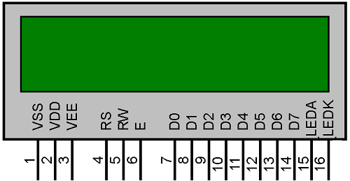
As you can see, the display has 16 pins and we can divide it into five categories, Power Pins, contrast pin, Control Pins, Data pins, and Backlight pins as shown in the table below. We will get into the details of each pin when we discuss the circuit diagram of this tutorial.
| Category | Pin NO. | Pin Name | Function |
| Power Pins | 1 | VSS | Ground Pin, connected to Ground |
| 2 | VDD or Vcc | Voltage Pin +5V | |
| Contrast Pin | 3 | V0 or VEE | Contrast Setting, connected to Vcc through a variable resistor. |
| Control Pins | 4 | RS | Register Select Pin, RS=0 Command mode, RS=1 Data mode |
| 5 | RW | Read/ Write pin, RW=0 Write mode, RW=1 Read mode | |
| 6 | E | Enable, a high to low pulse need to enable the LCD | |
| Data Pins | 7-14 | D0-D7 | Data Pins, Stores the Data to be displayed on LCD or the command instructions |
| Backlight Pins | 15 | LED+ or A | To power the Backlight +5V |
| 16 | LED- or K | Backlight Ground |
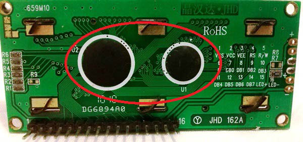
On the backside of the LCD, as shown in the image below, you will find two black dots, inside which we have the HD44780 LCD driver IC (encircled in red). Our microcontroller should communicate with this IC which in turn will control what is being displayed on the LCD. If you are curious to know how exactly all this works you should check out the working of 16x2 LCD display where we have already discussed how the LCD works in detail.
In this tutorial, we will discuss the circuit diagram and code to display alphamerical characters (alphabets and numbers) on a 16x2 LCD display using simple LCD_print_char and LCD_print_string commands. These commands can directly be used in the program after including our header file. The header file deals with all most of the stuff for you so it is not mandatory to know how the display or the HD44780 driver IC works.
Circuit Diagram to Interface LCD with STM8 Microcontroller
The complete STM8 LCD Circuit can be found in the below image. As you can see the connection for STM8S103F3P6 Controller with LCD is very simple, we have the LCD display directly connected to our board and the ST-link is also connected to program the board.

The power pins Vss and Vcc are connected to the 5V pin on the STM8S board, note that the operating voltage of LCD is 5V and is connected to operate on 3.3V. So even though the STM8S103F3P6 Microcontroller operates on 3.3V is mandatory to have a 5V supply for the LCD, you can avoid this by using a charge controller IC but we won’t be discussing that in this tutorial.
Next, we have the contrast pin which is used to set the contrast of the LCD, we have connected it to the potentiometer so that we can control the contrast. We have used a 10k pot, but you can also use other nearby values, the pot acts as a potential divider to provide 0-5 V to the contrast pin, typically you can also use a resistor directly to provide around 2.2V for reasonable contrast value. Then we have the reset (RS), Read/Write (RW), and Enable (E) pins. The read-write pin is grounded because we won’t be reading anything from the LCD we will only perform write operations. The other two control pins Rs and E are connected to PA1 and PA2 pins respectively.
Then we have the data pins DB0 to DB7. The 16x2 LCD can operate in two modes, one is an 8-bit operation mode where we have to use all the 8 data pins (DB0-DB7) on the LCD and the other is the 4-bit operation mode where we only need 4 data pins (DB4-DB7). The 4-bit mode is commonly used because it requires less GPIO pins from the controller, so we have also used 4-bit mode in this tutorial and have connected only pins DB4, DB5, DB6, and DB7 to pins PD1, PD2, PD3, and PD4 respectively.
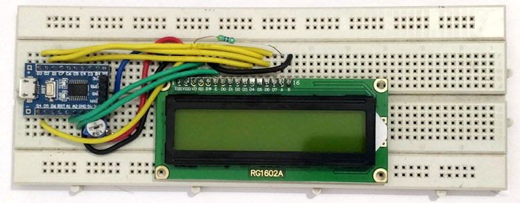
The last two pins BLA and BLK are used to power the internal backlight LED, we have used a 560-ohm resistor as a current limiting resistor. The ST-Link programmer is connected as always like in our previous tutorial. I made the complete connection on the breadboard and my set-up looks like this shown in the image below.
STM8 LCD Library – Header File for STM8S103F3P6
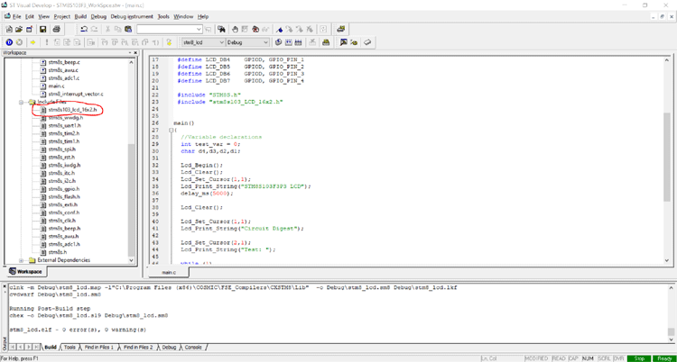
Before we proceed in the circuit diagram, let's get the STM8 LCD header file from GitHub using the following link-
You can either download the complete repo and get the stm8s103_LCD_16x2.h file or simple the code from the above link. While setting the project, make sure you include all the required header files in the inc directory along with this header file.
If you are not sure how to add the header files and compile the program, follow the video at the bottom of this page. And if you are curious about how the code inside the header file works, you can check out the PIC with an LCD tutorial. The header file used in this project is very similar to the one explained there, so we will not get into details of that.
LCD Program for STM8S Microcontroller
For the demonstration, we will program our STM8S controller to display a simple string like “Circuit Digest” and then we will increment a “Test” value for every one second in the second line. The complete program can be found at the bottom of this page. The explanation is as follows.
We start our program by defining the pins and adding the required header files as always. In our above discussed circuit diagram, we have connected LCD_RS to PA1 so we have defined it as LCD_RS GPIOA, GPIO_PIN_1. Similarly, we have done the same for other pins as well. If they are following a different circuit, make sure you change these values accordingly.
#define LCD_RS     GPIOA, GPIO_PIN_1
#define LCD_EN      GPIOA, GPIO_PIN_2
#define LCD_DB4    GPIOD, GPIO_PIN_1
#define LCD_DB5    GPIOD, GPIO_PIN_2
#define LCD_DB6    GPIOD, GPIO_PIN_3
#define LCD_DB7    GPIOD, GPIO_PIN_4
#include "STM8S.h"
#include "stm8s103_LCD_16x2.h"
Next inside our main program, we have declared the variables required for this sample code. We have a test variable called test_var which is initialized to zero, we will increment the variable and display it on the LCD. The characters d1 to d4 represents the 4 digits of the test variable because our LCD cannot display int value directly, we have to convert them to characters.
//Variable declarations
int test_var = 0;
char d4,d3,d2,d1;
The LCD_Begin() function is used to initialize the LCD. This function will initialize all the required GPIO pins and also set the LCD in 16x2 LCD mode. Then we have the LCD_Clear() function which is used to clear all the values on the LCD, this will erase everything on LCD so that it is clean to write new values. Then we have the LCD_Set_Cursor(x,y) function where x and y are the positions at which we need to write our new character. For example, (1,1) means first row and first Colum, similarly (2,12) means second row 12 column, likewise. Note that we have 2 rows and 16 columns here as we discussed earlier.
Lcd_Begin();
Lcd_Clear();
Lcd_Set_Cursor(1,1);
Now, the LCD is set, cleared, and the cursor is at the place. Next thing is to print something on the screen. We can use the LCD_Print_String(“Sample String”) to print a string to LCD and LCD_Print_Char(a) to print a character value to the LCD. In our program here we have printed “STM8S103F3P3 LCD” and created a delay of 5 seconds using the below code.
Lcd_Print_String("STM8S103F3P3 LCD");
delay_ms(5000);
After the 5 second delay, we clear the LCD again and display “Circuit Digest” in the first row and “Test:” I the second row.
Lcd_Clear();
Lcd_Set_Cursor(1,1);
Lcd_Print_String("Circuit Digest");
Lcd_Set_Cursor(2,1);
Lcd_Print_String("Test: ");
Inside the while loop, we will split the value on integer variable test_var into individual characters so that it can be displayed on the LCD using simple division and modulus operators. We have also added ‘0’ to convert the ASCII value to the character.
d4 = test_var%10 + '0';
d3 = (test_var/10)%10 + '0';
d2 = (test_var/100)%10 + '0';
d1 = (test_var/1000) + '0';
Then we have set the cursor to (2,6) because we have already written “Test:” in the second row which is 6 characters. If we overwrite, the existing character will be replaced with a new character on LCD. We have also added a delay 1 second and increment the variable.
Lcd_Set_Cursor(2,6);
Lcd_Print_Char(d1);
Lcd_Print_Char(d2);
Lcd_Print_Char(d3);
Lcd_Print_Char(d4);
delay_ms(1000);
test_var++;
STM8 with LCD – Working
To test our program, simply upload the code to our controller and power it up with the micro-USB port. Note that the LCD requires 5V for working so it is mandatory to power the board from the USB port. We have previously powered it directly from ST-link because we did not need the 5V supply.

As you can see the LCD is working as expected with the test variable value being increment for every second approximately. Also, note that we have not used timers and have only used delay function to create this delay so do not expect the delay duration to be accurate, we will use timers later in another tutorial for that purpose.
The complete working of the project can be found in the video linked below. Hope you enjoyed the tutorial and learned something useful. If you have any questions, leave them in the comment section or use our forums for other technical queries.
Complete Project Code
 /*Tutorial Number:4 Interfcaing 16x2 LCD with STM8s103F3
 * Website: https://circuitdigest.com/search/node/STM8S
 * Code by: Aswinth Raj
 */

 /*LCD --> STM8s
 * LCD_RS --> PA1
 * LCD_EN --> PA2
 * LCD_DB4 --> PD1
 * LCD_DB5 --> PD2
 * LCD_DB6 --> PD3
 * LCD_DB7 --> PD4
 */

 #define LCD_RS     GPIOA, GPIO_PIN_1
 #define LCD_EN     GPIOA, GPIO_PIN_2
 #define LCD_DB4    GPIOD, GPIO_PIN_1
 #define LCD_DB5    GPIOD, GPIO_PIN_2
 #define LCD_DB6    GPIOD, GPIO_PIN_3
 #define LCD_DB7    GPIOD, GPIO_PIN_4
 #include "STM8S.h"
 #include "stm8s103_LCD_16x2.h"
main()

{

//Variable declarations

int test_var = 0;
char d4,d3,d2,d1;
Lcd_Begin();
Lcd_Clear();
Lcd_Set_Cursor(1,1);
Lcd_Print_String("STM8S103F3P3 LCD");

delay_ms(5000);
Lcd_Clear();
Lcd_Set_Cursor(1,1);
Lcd_Print_String("Circuit Digest");
Lcd_Set_Cursor(2,1);
Lcd_Print_String("Test: ");

while (1)
{
d4 = test_var%10 + '0';
d3 = (test_var/10)%10 + '0';
d2 = (test_var/100)%10 + '0';
d1 = (test_var/1000) + '0';

Lcd_Set_Cursor(2,6);
Lcd_Print_Char(d1);
Lcd_Print_Char(d2);
Lcd_Print_Char(d3);
Lcd_Print_Char(d4);
delay_ms(1000);
test_var++;
}
}Comments
STM8S103FP6
How about a BME280 and a OLED? as a weather station?
Hello sir, very nice…
Hello sir,
very nice explanation for LCD interfacing
i am working on 7 Segment display interfacing with Stm8s103f3p3
i am having experience of Pic microcontroller
ST microcontrollers are new for me
i am facing difficulty for 7 Segment display interfacing with Stm8s103f3p3
can you please help

This is cool. Have you a list of all the tutorials that will be in the STM8 Microcontroller tutorials series?