
In this tutorial we will see how to interface NodeMCU with 16x2 LCD without using I2C communication. Here we will interface 16x2 LCD using shift register SN74HC595. We can also interface it even without using any shift register. We will see both kinds of interfacings in this tutorial. Main difference between both interfacings is the number of pins used in NodeMCU.
Material Required:
- NodeMCU ESP12E
- SN74HC595 Shift Register IC
- 16x2 LCD Module
- Potentiometers
- Male-Female wires
- Breadboard
Shift Register:
In digital systems, a shift register is a combination of flip-flops which are cascaded in series and shares the same clock. In this cascaded package, data-out of one flip-flop act as data-in for next flip-flop which results in a circuit that shifts by one position the bit array stored in it.
The IC which we are going to use is SN74HC595N. It is a simple 8-bit serial in parallel out shift register IC. In simple words, this IC allows additional inputs or outputs to be added to a microcontroller by converting data between parallel and serial formats. Our microcontroller use 3 pins of this IC to send data serially. Actually 8-bit output will be coming on 8 pins after getting 8-bits information from input pins. Learn more about shift registers here.
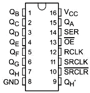
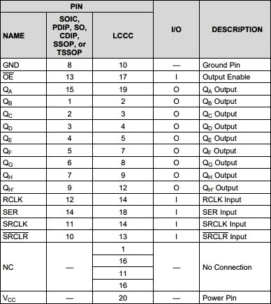
PIN diagram and PIN functions of IC SN74HC595N is given below:
You find interfacing of 74HC595N with Arduino and with Raspberry pi here.
Interface LCD with ESP12 without using Shift Register:
If you have used 16x2 LCD with the Arduino board then it will going be very easy. You have to just hookup pins in NodeMCU just same as you have done with Arduino board.
There are 16 GPIO pins in NodeMCU and we need 6 pins and gnd, vcc. Connect pins according to Circuit diagram given below:

We will use 4 data pins and RS, EN of LCD which are connected as:
d7 pin of LCD == D8 pin of NodeMCU
d6 pin of LCD == D7 pin of NodeMCU
d5 pin of LCD == D6 pin of NodeMCU
d4 pin of LCD == D5 pin of NodeMCU
RS pin of LCD == D2 pin of NodeMCU
En pin of LCD == D3 pin of NodeMCU
You can use any GPIO for these connections.
Now, upload the code using Arduino IDE as explained earlier. Code is same as for Arduino board which can be found in Liquidcrystal example. Program is simple and easily understandable if you want to learn more about the program check our LCD interfacing with Arduino Program.
CODE:
#include <LiquidCrystal.h>
const int RS = D2, EN = D3, d4 = D5, d5 = D6, d6 = D7, d7 = D8;
LiquidCrystal lcd(RS, EN, d4, d5, d6, d7);

void setup() {
                         // set up the LCD's number of columns and rows:
  lcd.begin(16, 2);
                      // Print a message to the LCD.
  lcd.print("hello, world!");
}

void loop() {
  // set the cursor to column 0, line 1
  // (note: line 1 is the second row, since counting begins with 0):
  lcd.setCursor(0, 1);
  // print the number of seconds since reset:
  lcd.print(millis() / 1000);
}
As we saw, we already used 6 pins of NodeMCU. There are already less pins available for this little board and we are left with few pins to interface other sensors.
So, to overcome with this problem we will use shift register IC which will minimize the no. of pins used on NodeMCU.
Interface LCD with ESP12 using Shift Register SN74HC595N:
There are 8 output and 3 input pins available in shift register IC. We will use 6 output pins to connect with the LCD and 3 input pins to NodeMCU.
Connections of LCD with IC are given as:
D7 pin of LCD == pin 1 of IC
D6 pin of LCD == pin 2 of IC
D5 pin of LCD == pin 3 of IC
D4 pin of LCD == pin 4 of IC
RS pin of LCD == pin 7 of IC
En pin of LCD == pin 15 of IC
Connection of NodeMCU with IC:
D6 pin of NodeMCU == pin 14 of IC, DATA PIN of IC
D7 pin of NodeMCU == pin 12 of IC, LATCH PIN of IC
D8 pin of NodeMCU == pin 11 of IC, CLOCK PIN of IC
Connect PIN 16 and PIN 10 of IC to Vcc.
Connect PIN 8 and PIN 13 of IC to GND.
Make Circuit carefully according to below diagram:

Now our Hardware is ready to program.
Now, we need a library “LiquidCrystal595” which can be downloaded from this link https://github.com/tehniq3/LiquidCrystal595 by following below steps:
1. Goto Sketch menu of Arduino IDE.
2. Click on Include Library.
3. Now, click on Add .zip library. Choose zip file you have downloaded from given link and its done.
Now upload the code given below and you will see message printing the LCD.
CODE:
#include <LiquidCrystal595.h>    // include the library
LiquidCrystal595 lcd(D6,D7,D8);     // data_pin, latch_pin, clock_pin
void setup() {
    lcd.begin(16,2);             // 16 characters, 2 rows
    lcd.clear();
    lcd.setCursor(0,0);
    lcd.print("lcd with nodemcu");
}

void loop() {
   lcd.setCursor(0,1);
    lcd.print("Success");
}
The code is simple as we have to just give data pin, latch pin and clock pin as argument in LiquidCrystal595 lcd(); and rest of the code is same as we have done previously.
In this way, you have just saved 3 pins of NodeMCU by using Shift Register.
Also, check 16x2 LCD interfacing with other Microcontrollers:

how to interface non i2c 16x2 lcd to nodemcu directly without shiftregister?