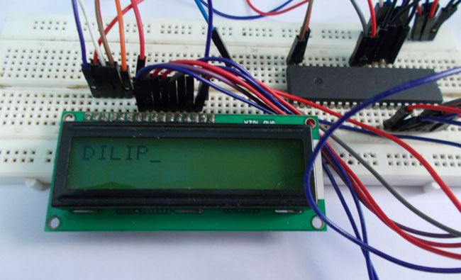
To establish a good communication between human world and machine world, display units play an important role. And so they are an important part of embedded systems. Display units - big or small, work on the same basic principle. Besides complex display units like graphic displays and 3D dispays, one must know working with simple displays like 16x1 and 16x2 units. The 16x1 display unit will have 16 characters and are in one line. The 16x2 LCD will have 32 characters in total 16in 1st line and another 16 in 2nd line. Here one must understand that in each character there are 5x10=50 pixels so to display one character all 50 pixels must work together. But we need not to worry about that because there is another controller (HD44780) in the display unit which does the job of controlling the pixels. (you can see it in LCD unit, it is the black eye at the back ).
Components Required
Hardware:
ATmega32 microcontroller
Power supply (5v)
AVR-ISP Programmer
JHD_162ALCD (16x2 LCD)
100uF capacitor.
Software:
Atmel studio 6.1
Progisp or flash magic
Circuit Diagram and Explanation
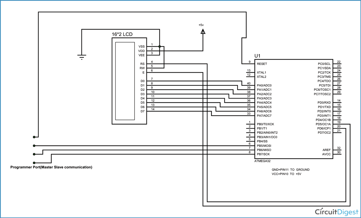
As shown in the LCD interfacing with ATmega32 circuit, you can see that PORTA of ATMEGA32 connected to data port LCD. Here one should remember to disable the JTAG communication in PORTC of ATMEGA by changing the fuse bytes, if one wants to use the PORTC as a normal communication port. In 16x2 LCD there are 16 pins over all, if there is a back light, if there is no back light there will be 14 pins. One can power or leave the back light pins. Now in the 14 pins there are 8 data pins (7-14 or D0-D7), 2 power supply pins (1&2 or VSS&VDD or gnd&+5v), 3rd pin for contrast control (VEE-controls how thick the characters should be shown), 3 control pins (RS&RW&E)
In the above circuit to interface 16x2 LCD with AVR microcontroller, you can observe tht I have only took two control pins. This give the flexibility of better understanding. The contrast bit and READ/WRITE are not often used so they can be shorted to ground. This puts LCD in highest contrast and read mode. We just need to control ENABLE and RS pins to send characters and data accordingly.
The connections between ATmega32 microcontroller and 16x2 LCD are given below:
PIN1 or VSS - ground
PIN2 or VDD or VCC - +5v power
PIN3 or VEE - ground (gives maximum contrast best for a beginner)
PIN4 or RS (Register Selection) - PD6 of microcontroller
PIN5 or RW (Read/Write) - ground (puts LCD in read mode eases the communication for user)
PIN6 or E (Enable) - PD5 of microcontroller
PIN7 or D0 - PA0 of microcontroller
PIN8 or D1 - PA1
PIN9 or D2 - PA2
PIN10 or D3 - PA3
PIN11 or D4 - PA4
PIN12 or D5 - PA5
PIN13 or D6 - PA6
PIN14 or D7 - PA7
In the circuit you can see we have used 8bit communication (D0-D7) however this is not compulsory and we can also use 4bit communication (D4-D7) but with 4 bit communication program becomes a bit complex for beginners so just we went with 8 bit communication.
So from mere observation from above table we are connecting 10 pins of LCD to controller in which 8 pins are data pins and 2 pins for control.
Working
Now to get started you must know the functions of 10 pins of 16x2 LCD (8 data pins + 2 control pins). The 8 data pins are for sending data or commands to LCD. In two control pins:
1. RS (Register selection) pin is to tell the LCD whether we are sending data to it or command to it.
For example:
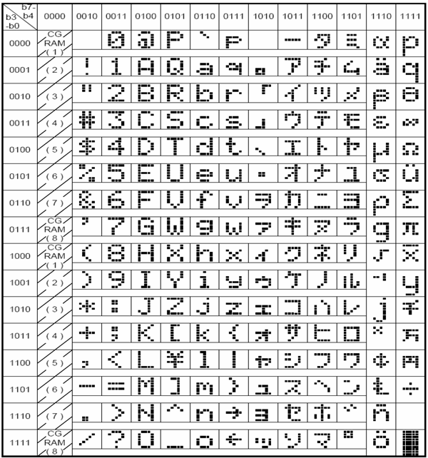
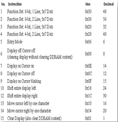
In above table one for a Data port (D7-D0) value of “0b0010 1000 or 0x28” tells the LCD to display “(” symbol. In table two the same value of 0x28 tells the LCD “you are a 5x7 dot LCD and behave like one”, so for same value the user can define two things, now this situation is neutralized by Register Selection pin, if the RS pin is set low then LCD understands that we are sending command. If we set RS pin to high then LCD understands we are sending the data. And so in both cases the LCD respects the data port value according to RS pin value.
2. E (Enable) pin is simply to tell “power indication LED of a PC”, this pin is set to high to tell the LCD “to receive data form data port of controller”. Once this pin goes low after high, the LCD process the received data and show the corresponding result. So this pin is set to high before sending data and pulled down to ground after sending data.
Now after connecting the hardware, start Atmel studio and start a new project for writing the program, now open programming screen and start wring program. The program has to follow as show following.
First we tell the controller which ports we are using for data and control of LCD. Then tell the controller when to send data or a command accordingly by playing with RS and E pins.
Brief explanation of the concepts used in the program:
1. E is set high (telling LCD to receive data) and RS is set low (telling LCD we are giving command)
2. Giving value 0x01 to data port as a command to clear screen
3. E is set high (telling LCD to receive data) and RS is set high (telling LCD we are giving data)
4. Taking a string of characters sending each character in a string one by one.
5. E is set low (telling LCD that we are done sending data)
6. After the last command the LCD terminates communication and processes the data and displays the string of characters on screen.
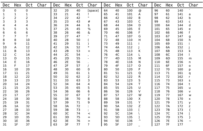
In this scenario we are going to send the characters one after the other. The characters are given to LCD by ASCII codes (American standard Code for Information Interchange).
The table of ASCII codes is shown above. Here for the LCD to show a character “@” we need to send a hexadecimal code “64”. If we send ‘0x62’ to the LCD it will show ‘>’ symbol. Like this we are going to send the appropriate codes to the LCD to display a name.
The way of communication between LCD and ATmega32 AVR microcontroller is best explained in step by step of C code down below,
Complete Project Code
// Code for LCD Interfacing with ATmega32 AVR microcontroller

#include <avr/io.h>

#define F_CPU 1000000UL

#include <util/delay.h>
#define RS 6

#define E  5
void send_a_command (unsigned char command);

void send_a_character(unsigned char character);
int main(void)

{

    DDRA = 0xFF;

    DDRD = 0xFF;

    _delay_ms(50);

    send_a_command(0x01);// sending all clear command

    send_a_command(0x38);// 16*2 line LCD

    send_a_command(0x0E);// screen and cursor ON


     send_a_character (0x44); // ASCII(American Standard Code for Information Interchange) code for 'D'

     send_a_character (0x49); // ASCII(American Standard Code for Information Interchange) code for 'I'

     send_a_character (0x4C); // ASCII(American Standard Code for Information Interchange) code for 'L'

     send_a_character (0x49); // ASCII(American Standard Code for Information Interchange) code for 'I'

     send_a_character (0x50); // ASCII(American Standard Code for Information Interchange) code for 'P'


}
void send_a_command (unsigned char command)

{

    PORTA=command;

    PORTD&= ~(1<<RS);

    PORTD|= (1<<E);

    _delay_ms(50);

    PORTD&= ~(1<<E);

    PORTA =0;

}
void send_a_character (unsigned char character)

{

    PORTA=character;

    PORTD|= (1<<RS);

    PORTD|= (1<<E);

    _delay_ms(50);

    PORTD&= ~(1<<E);

    PORTA =0;

}
Comments
nothing is visible on screen
Great Thanks
Hi..
can you please describe me how do I print on the second line of the LCD... thanks for the great tutorial :D \m/
First bring the cursor on second line, Position 1 by sending the command using send_a_command(0xC1); then print character using send_a_character function.
/* C0-REGISTER SELECT C1-READ/WRITE C3-ENABLE
* C0 BIT-HIGH DISPLAY DATA MODE
* C0 BIT-LOW COMMAND MODE
* C1 BIT-HIGH READS DATA FROM LCD
* C1 BIT-LOW WRITES DATA TO LCD
* C3 BIT-HIGH ENABLE SEEING THE LCD
* C3 BIT-LOW DISABLE SEEING THE LCD
* D0-D7 DATA BUS
* IN COMMAND MODE
* D2-FONT SIZE
* D3-NUMBER OF DISPLAY LINES
* D4-DATA LENGTH */
#include<avr/io.h>
#include<util/delay.h>
#define RS 0
#define RW 1
#define EN 3
#define data PORTD
#define ctrl PORTC
void enable()
{
ctrl|=(1<<EN);
_delay_ms(20);
ctrl|=(0<<EN);
_delay_ms(20);
}
void checkstatus()
{
DDRD|=0x00;
PORTC|=(1<<RW)|(0<<RS);
while(data>=0x80)
{
enable();
}
DDRD|=0xFF;
}
void sendcommand(char command)
{
ctrl|=(0<<RS)|(0<<RW);
data=command;
enable();
_delay_ms(10);
DDRB=0;
}
void sendcharacter(char character)
{
data=character;
ctrl|=(1<<RS)|(0<<RW);
enable();
_delay_ms(10);
DDRB=0;
}
int main()
{
DDRB|=0;
DDRC|=(1<<RS)|(1<<RW)|(1<<EN);
_delay_ms(50);
sendcommand(0x01);//all clear
sendcommand(0x38);//to notify that we are sending 8 bits of values
sendcommand(0x0F);//display character and blink cursor
sendcommand(0x10);//cursor to line1
data=0x00;
sendcharacter(0x48);
sendcharacter(0x49);
return 0;
}
This is my code I uploaded it my my arduino UNO.The LCD just shows BLACK BOXES in the first line of the module
I want a general coding for at mega 328 microcontroller
very simple and explicit tutorial. keep it up. Please i need tutorial for 328 4 bit mode. thanks
I have a more easy connection of 328.
can any one send me .. program
Simulation working but physical/ actual circuit not working, showing second line box only



very good presentation.