
NAND Gate
|
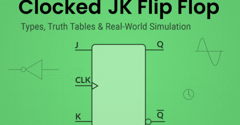
Clocked JK Flip Flop: Complete Guide with Circuit, Truth Table, and Working In the world of flip-flops, the Clocked JK Flip Flop stands out with its outstanding features, such as all usable input states and the ability to be modified to imitate other flip-flops like SR, T, and D. This makes the JK Flip Flop a little better than the others. It's often called a universal flip-flop. The JK flip-flop's main… |
|
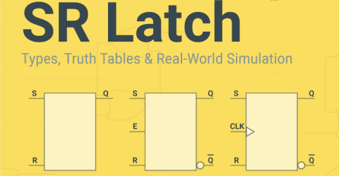
Understanding SR Latches: Complete Guide to Set-Reset Latch, Gated & Clocked Versions An SR latch is a basic memory element in digital electronics that stores binary data using Set and Reset inputs. This tutorial covers the SR latch truth table, the circuit diagram, and the working principle of basic, gated, and clocked SR latch variants. Initially, after the introduction of transistors, engineers constructed simple latch circuits using transistors. After several… |

|
Flip-Flop in Digital Electronics: Types, Truth Table, Logic Circuit and Practical Demonstration A flip-flop in digital electronics is formally defined as "A bistable device with synchronous inputs that changes state only at specified transitions of a clock signal" (IEEE Standard 91/1984) In general, flip-flops are fundamental components in digital electronics, capable of functioning as 1-bit memory storage devices. Unlike… |

|
How to Build a NAND Gate with Transistors? In the realm of digital electronics and logic circuits, the NAND gates stands as a fundamental cornerstone that wields immense power in information processing. NAND, short for Negated AND, is a logical operation that produces an output of low only when all of its inputs are high. In this article, we will… |

|
What is Switch Bouncing and How to prevent it using Debounce Circuit Table of Contents What is Switch Bouncing and Debouncing? What is Software Debouncing? Switch Bouncing Circuit Diagram 1. Hardware Debouncing └ Components Required └ Debounce Circuit Diagram └ Working of the Hardware Debounce Circuit 2. RC Debounce Circuit 3. Debouncing Circuit for Push Button Using Specialised ICs Debouncing Methods… |
|
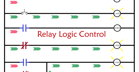
Introduction to Relay Logic Control - Symbols, Working and Examples Relay logic control systems are truly a foundation of industrial automation, and electromagnetic relays are necessary to perform switching actions in these conversion systems. The relay logic circuits also utilise relays along with switches, motors, timers, actuators, and contactors to form ON/OFF control systems effectively. Though relay logic control proves to be effective… |
|
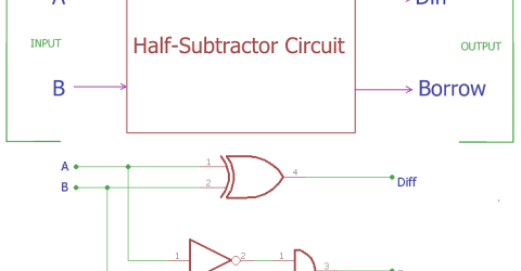
Half Subtractor Circuit and Its Construction In previous tutorials, we have seen how computer use binary numbers 0 and 1 and by using an adder circuit computer will add those digits to provide SUM and Carry Out. We have already covered Half Adder and Full Adder circuits in previous tutorials. Today we will learn about Subtractor circuits. Subtractor circuits use this binary numbers 0, 1 and calculate the subtraction.… |
|
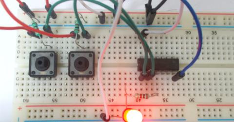
NAND Gate NAND gate is a digital logic gate, designed for arithmetic and logical operations, every electronic student must have studied this gate is his/her career. This gate is mainly used in applications where there is a need for mathematical calculations. So calculators, computers and many digital applications use this gate. … |