

In previous tutorials, we have seen how computer use binary numbers 0 and 1 and by using an adder circuit computer will add those digits to provide SUM and Carry Out. We have already covered Half Adder and Full Adder circuits in previous tutorials. Today we will learn about Subtractor circuits. Subtractor circuits use this binary numbers 0, 1 and calculate the subtraction. A binary Half-Subtractor circuit can be made using EX-OR and NAND (Combination of NOT and AND gate) gates. The circuit provides two elements. First one is the Diff (Difference) and second one is the Borrow.
When we use arithmetic subtraction process in our base 10 mathematics, like subtracting two numbers, for an example-
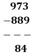
We subtract each column from right to left and if the subtrahend is greater than the minuend, borrow is required from the previous column. If we see the example, we will understand this much better. In the most right column, the subtrahend 9 is bigger than the minuend 3. In such case, we can’t subtract 9 from 3, we take borrow 10 (as per our base 10 mathematics) from the next left column and convert the 3 to 13 and then do the subtraction, 13 – 9 = 4, we move to the next column, now due to the borrow the minuend is 6 not 7. Again the subtrahend 8 is bigger than the minuend 6, we again took borrow from the left most column and we do the subtraction 16 – 8 = 8. Now on the most left column the minuend is 8 not 9. By subtracting these two numbers we get, 8 – 8 = 0. This is exactly opposite of the addition we described in our previous half-adder tutorial.
Binary Subtraction:
In case of binary number, subtraction process is exactly same. Instead of the base 10 number system, here base 2 number system or binary numbers are used. We only get two numbers in binary number system 1 or 0. This two numbers can represent Diff (Difference) or Borrow or both. As in binary number system, 1 is the largest digit, we only produce borrow when the subtrahend 1 is greater than minuend 0 and due to this, borrow will require.
Let’s see possible binary subtraction of two bits,
| 1st Bit or Digit | 2nd Bit or Digit | Difference | Borrow |
| 0 | 0 |
0 |
0 |
| 1 | 0 | 1 | 0 |
| 0 | 1 | 1 | 1 |
| 1 | 1 | 0 | 0 |
The first digit, we can denote as A and the second digit we can denote as B are subtracted together and we can see the subtraction result, Difference and Borrow bit. In the first two row and the last row 0 - 0, 1 - 0 or 1 - 1 the Difference is 0 or 1 but there is no borrow bit. But in the third row we subtracted 0 - 1 and it produces a borrow bit of 1 along with result 1 because the subtrahend 1 is greater than the minuend 0.
So, if we see the operation of a Subtractor circuit, we need only two inputs and it will produce two outputs, one is subtraction result, denoted as Diff (Short form of Difference) and other one is Borrow bit.
Half Subtractor:
So, the block diagram of a Half-Subtractor, which requires only two inputs and provide two outputs.
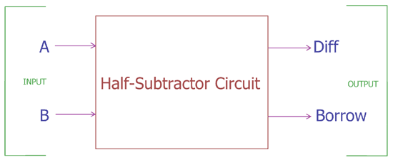
In the above block diagram, a Half-Subtractor circuit with input-output construction is shown. We can make this circuit using EX-OR and NAND Gate. For making NAND gate, we have used AND gate and NOT gate. So we need three gates to construct Half Subtractor circuit:
- 2-input Exclusive-OR Gate or Ex-OR Gate
- 2-input AND Gate.
- NOT Gate or Inverter Gate
Combination of AND and NOT gate produce a different combined gate named as NAND Gate. The Ex-OR gate is used to produce the Diff bit and NAND Gate produce the Borrow bit of the same input A and B.
Ex-OR Gate:
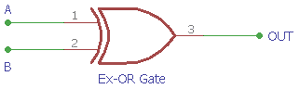
This is the symbol of two inputs EX-OR gate. A and B is the two binary input and OUT is the final output.
This output will be used as Diff Out in half Subtractor circuit.
The truth table of EX-OR gate is –
| Input A | Input B | OUT |
| 0 | 0 | 0 |
| 0 | 1 | 1 |
| 1 | 0 | 1 |
| 1 | 1 | 0 |
In the above table we can see the output of the EX-OR gate. When any one of the bits A and B is 1 the output of the gate becomes 1. On the two other cases when both inputs are 0 or 1 the Ex-OR gate produce 0 outputs. Learn more about EX-OR gate here.
2-input AND Gate:
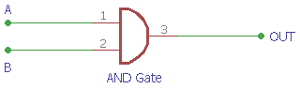
This is the basic circuit of two input AND gate. Same as like EX-OR gate, it has two inputs. If we provide A and B bit in the input it will produce an Output.
The truth table of AND gate is –
|
Input A |
Input B |
Carry Output |
|
0 |
0 |
0 |
|
0 |
1 |
0 |
|
1 |
0 |
0 |
|
1 |
1 |
1 |
Truth table of AND gate is shown above where it will only produce the output when both inputs are 1, Otherwise it will not provide an output if both or any of the input is 0. Learn more about AND gate here.
NOT Gate or Inverter Gate:
Below is the symbol of Inverter Gate:
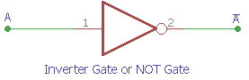
|
Input A |
Output |
|
0 |
1 |
|
1 |
0 |

As we can see from the truth table of NOT gate, the input is inverted by the gate. So it produced an inverted output.
Combining this two gates AND and NOT gate we make a combinational gate NAND gate. Learn more about NOT gate here.
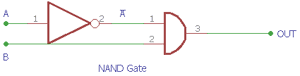
Input A is inverted by the NOT gate and the output is used as an input of AND gate. Output from this NAND gate is used as borrow bit in half adder circuit.
Half-Subtractor Logical Circuit:
So a Half-Subtractor logical circuit can be made by combining two gates Ex-OR and NAND gate.
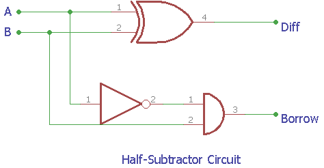
This is the construction of Half-Subtractor circuit, as we can see two gates are combined and the same input A and B are provided in both gates and we get the Diff output across EX-OR gate and the Borrow bit across NAND gate.
The Boolean expression of Half Subtractor circuit is-
DIFF = A XOR B
BORROW = not – A AND B (A’.B)
Truth table of Half-Subtractor circuit is as follows-
|
Input A |
Input B |
DIFF(XOR out) |
Borrow(NAND out) |
|
0 |
0 |
0 |
0 |
|
1 |
0 |
1 |
0 |
|
0 |
1 |
1 |
1 |
|
1 |
1 |
0 |
0 |
Practical Demonstration of Half Subtractor Circuit:
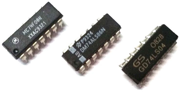
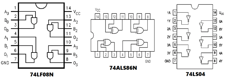
We can make the circuit in real on Breadboard to understand it clearly; for this we have used three widely used XOR, AND and NOT chip from 74 series 74LS86, 74LS08, and 74LS04.
74LS86 has four XOR gates inside the chip and 74LS08 has four AND gates inside it where as 74LS04 has six NOT gate inside it. These three ICs are widely available and we will make Half-Subtractor circuit using these three. Below are the pictures of those three ICs.
We can also see the pin diagram in the below image-
For making the half-Subtractor circuit we will need following components-
- Green LED – 1 pc
- Red LED – 1 pc
- 74LS86
- 74LS08N
- 74LS04
- 1pc 4pin DIP switch
- 2pcs 4.7k resistor
- 2pcs 1k resistor
- 5V wall adapter
- Breadboard and hook up wires
Circuit Diagram to use these three ICs as a half-Subtractor circuit-

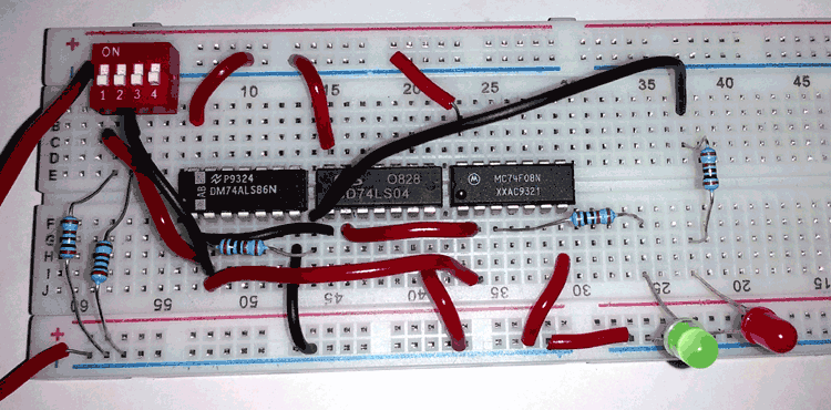
We constructed the circuit in breadboard and observed the output.
In the above circuit diagram one of the XOR gate from 74LS86, one of the AND gate from 74LS08 and a NOT gate from 74LS04 are used. Pin 1 and 2 of 74LS86 are the inputs of the Ex-OR gate and pin 3 is the output from the gate, on the other side pin 1 and 2 of 74LS08 is the input of the AND gate and pin 3 is the output from the gate, pin1 from the 74LS04 is the input of inverter gate and pin2 is the output of inverter gate.
As per the pin diagram, 7th pin of those ICs are connected to GND and 14th pin of those ICs are connected to VCC. In our case the VCC is 5v. We added two LEDs to identify the output. When the output is 1, the LED will glow. Here Red LED is used for the Diff and Green LED is used for the Borrow bit.
We added DIP switch in the circuit to provide input on the gates, for the bit 1 we providing 5V as input and for 0 We providing GND through 4.7k resistor. 4.7k resistors are used to provide 0 inputs when the DIP switch is in off state.
Demonstration Video is given below.
Half Subtractor circuit is used for bit subtraction and logical output related operations in computers.
