
NOT Gate

|
Flip-Flop in Digital Electronics: Types, Truth Table, Logic Circuit and Practical Demonstration A flip-flop in digital electronics is formally defined as "A bistable device with synchronous inputs that changes state only at specified transitions of a clock signal" (IEEE Standard 91/1984) In general, flip-flops are fundamental components in digital electronics, capable of functioning as 1-bit memory storage devices. Unlike… |
|
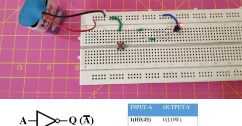
Designing NOT Gate using Transistors An Integrated Circuit or IC is a combination of many small circuits in a small package that together performs a common task. For example, an Operational Amplifier or 555 Timer IC is built by a combination of many Transistors, Flip-Flops, Logic Gates and other combinational digital circuits. Similarly, a Flip-Flop can be built by using a… |
|
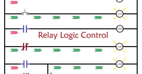
Introduction to Relay Logic Control - Symbols, Working and Examples Relay logic control systems are truly a foundation of industrial automation, and electromagnetic relays are necessary to perform switching actions in these conversion systems. The relay logic circuits also utilise relays along with switches, motors, timers, actuators, and contactors to form ON/OFF control systems effectively. Though relay logic control proves to be effective… |
|
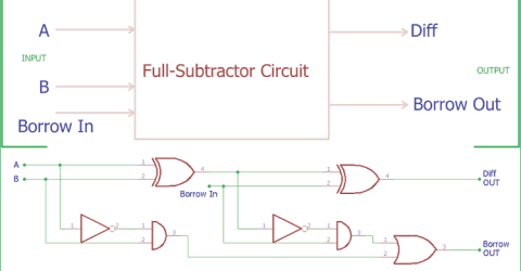
Full Subtractor Circuit and Its Construction In the previous tutorial of Half Subtractor Circuit, we had seen how computer use single bit binary numbers 0 and 1 for subtraction and create Diff and Borrow bit. Today we will learn about the construction of Full-Subtractor circuit. Full Subtractor CircuitHalf-Subtractor circuit has a major drawback; we do not have the scope to provide… |
|
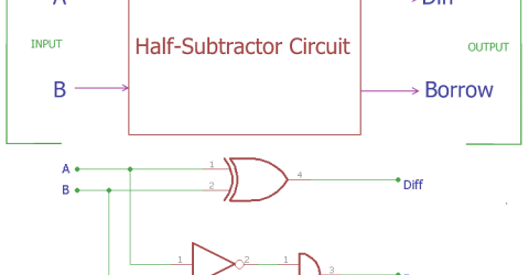
Half Subtractor Circuit and Its Construction In previous tutorials, we have seen how computer use binary numbers 0 and 1 and by using an adder circuit computer will add those digits to provide SUM and Carry Out. We have already covered Half Adder and Full Adder circuits in previous tutorials. Today we will learn about Subtractor circuits. Subtractor circuits use this binary numbers 0, 1 and calculate the subtraction.… |
|
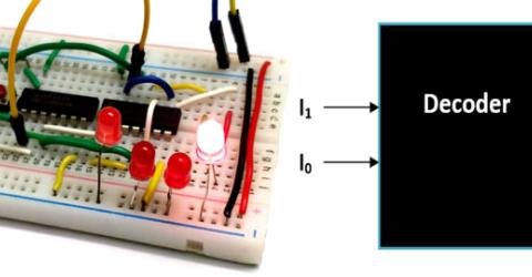
Binary Decoders Decoder is type of combinational Circuit which decodes a small bit value into large bit value. It is normally used in combination with encoders which does exactly the opposite of what a decoder does, so read about Encoders here before you proceed with Decoders. Again just like Encoders there are many types of Decoders as well but the number of output lines in a decoder will… |
|
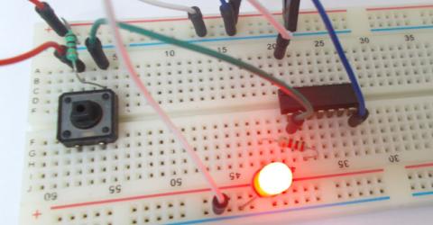
NOT Gate NOT gate is a digital logic gate, designed for arithmetic and logical operations, every electronic student must have studied this gate is his/her career. This gate is mainly used in applications where there is a need for mathematical calculations. So in calculators, computers and many digital applications use this gate. … |