

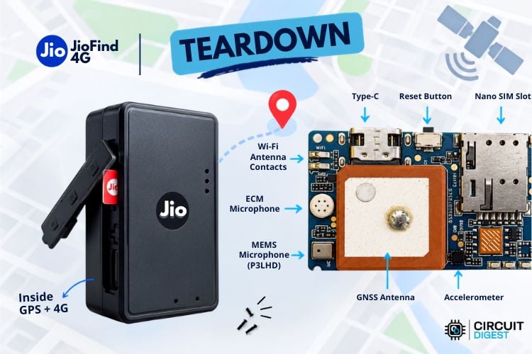
Bluetooth trackers like Apple AirTags and Samsung SmartTag are a convenient way to locate misplaced items nearby, but their dependence on nearby smartphones limits their usefulness over long distances. Cellular GPS trackers overcome this limitation by communicating directly over the mobile network, allowing them to report their location from anywhere with network coverage. This makes them useful for tracking vehicles, luggage, school bags, pets, and other valuable belongings. In this GPS tracker teardown, we open up the Jio Find 4G (Model number: JAT6020), Reliance Jio's compact GPS tracking device designed for this purpose. Priced at ₹1499, it combines 4G connectivity and GPS-based location tracking in a small form factor. The tracker is powered by a built-in 1100 mAh rechargeable battery, with a claim of up to 3 days of battery life on a single charge, depending on usage and tracking activity. The device is charged through a USB Type-C port and comes with a bundled Jio SIM and one year of service included.
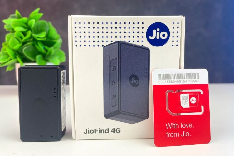
Unlike traditional GPS trackers that require users to have an independent data plan, the Jio Find uses Jio's number-sharing technology. This allows the tracker to be linked with an existing Jio mobile connection, sharing the user's Jio plan instead of requiring a separate mobile subscription. Even though they mention "no exact cost", the product page also mentions that we have to pay a charge of ₹599 from the second year onwards. Jio customer care confirmed that only the first year of service is complimentary, and afterwards users have to pay the yearly charges along with the number sharing. Since the device relies on the bundled Jio SIM and Jio's network services, it is designed specifically for users within the Jio ecosystem and does not support SIM cards from other telecom operators. The tracker is controlled through the Jio Things mobile application, which provides features such as live location tracking, location history, geofencing, overspeed alerts, low-battery notifications, and ambient voice monitoring. Using geofencing, users can create custom safe zones on the map and receive alerts whenever the device enters or exits those areas. The voice monitoring feature allows short ambient audio recordings of 30 seconds to be triggered remotely through the app for security and monitoring purposes. A single Jio account can support up to five Jio Find devices through the number-sharing system.
On paper, the Jio Find offers a wide range of features for a compact IoT device in this price segment. However, the more interesting question from a hardware perspective is how these functions are implemented inside such a small enclosure while maintaining reasonable battery life and keeping the overall cost low. In this teardown, we will open the Jio Find 4G GPS Tracker and examine its internal hardware in detail.
What's in the Box
Opening the retail package reveals a fairly minimal set of accessories, which is expected for a compact IoT tracking device. Along with the Jio Find 4G tracker itself, Jio includes a short USB Type-C charging cable and a Jio 4G SIM card. No power adapter is included in the box, so users will need to use any standard USB charger or a computer USB port for charging. The package also includes a Velcro sticker, which can be used to attach the tracker to any surface, making it easier to remove for charging.
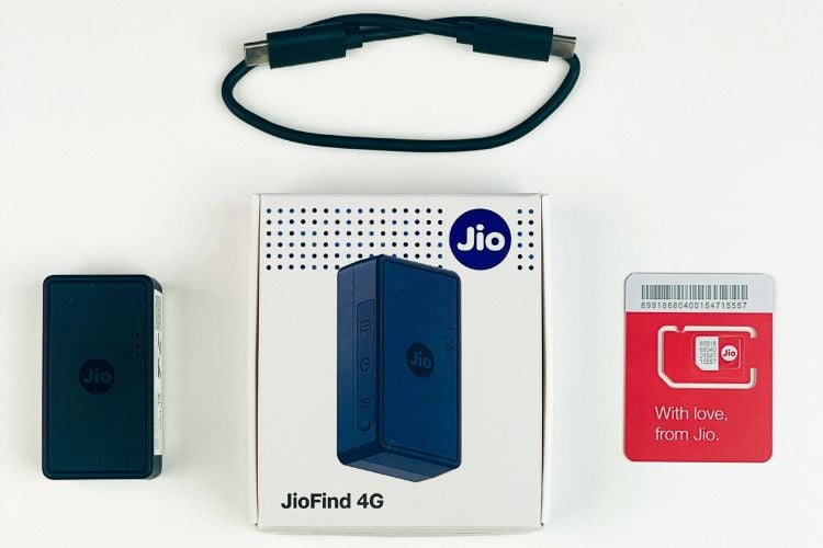
Unlike many GPS trackers that require users to purchase and configure a separate SIM card, Jio simplifies the setup by providing a dedicated SIM as part of the package. During activation, this SIM is paired with the user's Jio account through the JioThings application using Jio's Number Sharing feature, eliminating the need for an additional payment during the first year of service. Overall, the packaging is simple and functional, containing only the essentials required to get the tracker up and running.
External Design and Build Quality
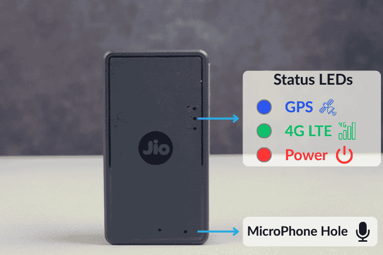
At first glance, the Jio Find 4G resembles a compact portable battery pack rather than a conventional GPS tracker. Measuring approximately 57 × 31 × 18 mm and weighing around 41 g, the device is small enough to fit inside a backpack, luggage, or vehicle compartment without attracting attention. The enclosure is constructed entirely from matte-finished plastic with gently rounded edges, giving it a clean appearance while also providing a reasonable grip during handling. The front of the device is intentionally minimalistic, featuring only the Jio logo at the centre along with two groups of small openings. The three closely spaced openings are for the status indicator LEDs, while the two smaller holes are used for the built-in microphone for the ambient voice monitoring feature. The red LED serves as the power and battery indicator, remaining ON while charging and blinking once per second when the battery level falls to 30% or below, or three times per second when it is above 30%. The green LED indicates the device's 4G LTE network status, while the blue LED shows the GPS status, blinking rapidly while searching for satellites, remaining steadily ON after a successful GPS fix, and turning OFF when the GPS receiver is inactive or in sleep mode.
One side of the tracker houses a rubber protective cover that conceals the external connectors and controls. Opening this flap reveals the USB Type-C charging port, the Nano SIM card slot, and a multifunction power button. The rubber cover sits firmly in place and helps protect these openings from dust and accidental exposure during everyday use. An interesting design choice is the presence of a user-accessible SIM slot. Although the tracker physically accepts a removable Nano SIM card, the bundled firmware is designed to operate only with the supplied Jio SIM and associated network services. This makes the hardware appear more flexible than it actually is, as replacing the SIM with another operator's card is not supported by the software.
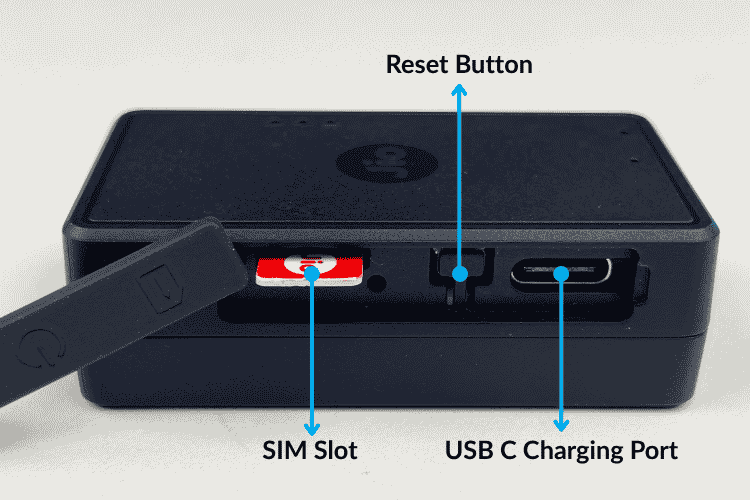
The USB Type-C connector is another welcome addition. Many entry-level GPS trackers continue to rely on Micro-USB, but adopting USB-C makes charging more convenient and improves long-term durability. The bundled charging cable is relatively short. From the outside, the Jio Find 4G gives very little indication of the amount of electronics packed inside. The clean enclosure hides a complete circuitry comprising a 4G modem, GNSS receiver, rechargeable battery, antennas, microphone, and power management circuitry. The next step is to open the enclosure and see how Jio has integrated all of these components into such a compact form factor.
Block Diagram
For easy understanding of each distinct part of the Jio Find 4G, we have prepared a block diagram as follows.
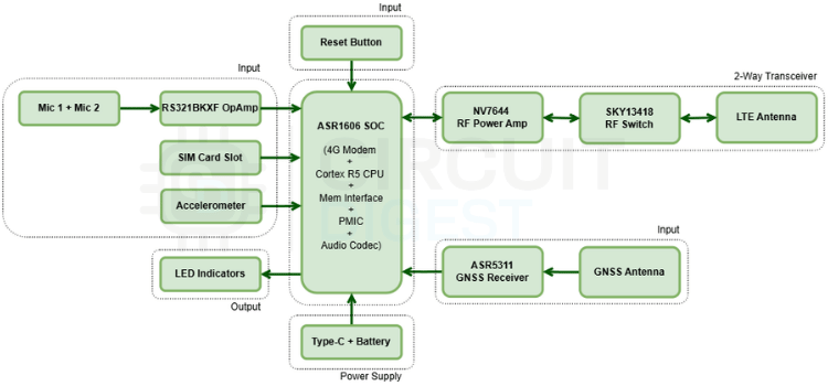
All of the IO devices, ICs, antennas and power supply parts are clearly differentiated and labelled in the block diagram. From our observations, the two mics with the pre-amp circuit, SIM card slot, accelerometer, reset button and the GNSS section form the Input part of the device that gives some kind of inputs or signals to the Jio Find 4G. The LED indicators form a physical output as they show the status indications.
The Type-C connector, its associated circuitry and the battery form the power supply part of the device. The LTE circuitry, consisting of the RF Power Amp, RF Switch and the LTE Antenna, forms a two-way transceiver section that does the two-way communication with the external world. All those peripherals or IO devices are connected to the main processor, which is the ASR1606. Breaking down a complicated circuit into a simplified block diagram like this helps us to understand the whole circuit more easily.
A Look Inside the JioFind 4G
Unlike many modern consumer electronics that rely on adhesives or ultrasonic welding, the Jio Find 4G is surprisingly easy to open. The two-piece plastic enclosure is held together entirely by a series of internal plastic retaining clips around the perimeter. There are no hidden screws or glue, allowing the enclosure to be separated with a thin plastic pry tool without causing any permanent damage. Once the retaining clips are released, the top cover lifts away to reveal that the majority of the internal volume is occupied by the rechargeable lithium-polymer battery. The battery is positioned directly over the PCB without the use of adhesive, allowing it to be lifted aside easily during disassembly.
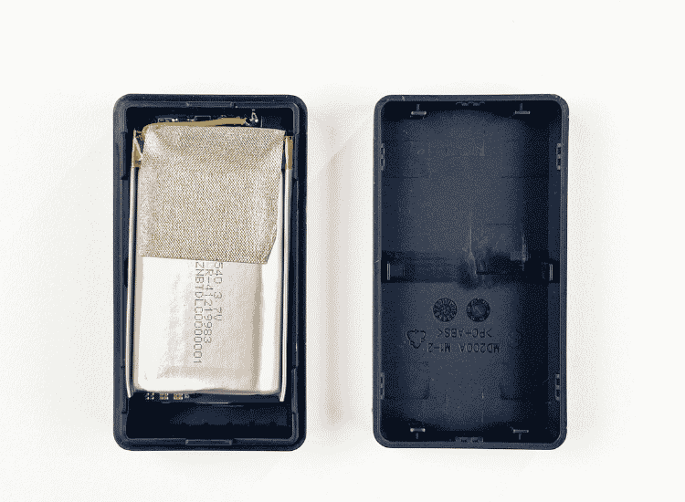
The battery is rated at 1100 mAh with a nominal voltage of 3.7 V, matching the capacity specified by Jio. Based on its dimensions, the cell occupies a significant portion of the device, explaining how the tracker is able to achieve a claimed battery life of up to three days despite continuously operating a 4G modem and GNSS receiver.
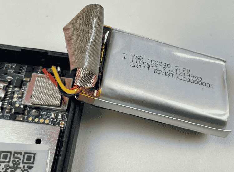
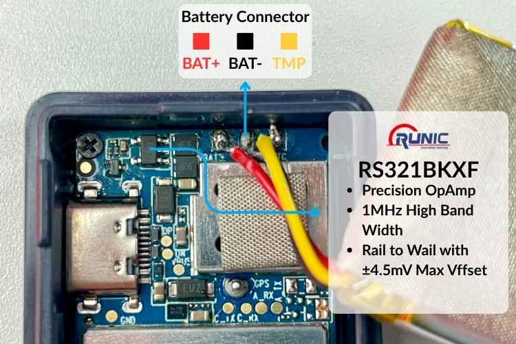
Unlike many portable devices that use a small JST connector, the battery in the Jio Find 4G is directly soldered to the PCB using three wires for the positive terminal, negative terminal, and battery temperature sensor. While this approach reduces manufacturing cost, improves mechanical reliability, and saves valuable PCB space, it also makes battery replacement slightly more involved, as the cell must be desoldered instead of simply unplugged. While the solder joints appear functional, the soldering quality is not as neat as the rest of the board.
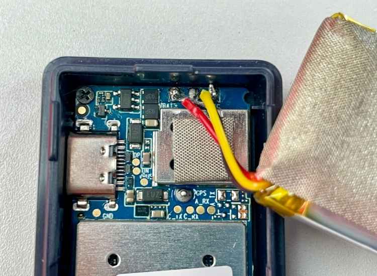
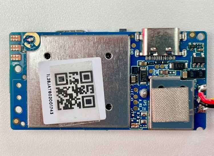
With the battery gently folded aside, the main PCB becomes visible. The board is secured to the enclosure using two small screws and is almost completely covered by metal RF shields on the top side, indicating that the majority of the high-frequency circuitry, including the cellular modem and GNSS receiver, is located beneath these shields. At the top of the PCB are the USB Type-C charging connector and the mic preamp circuitry, while several unpopulated test pads can also be seen, suggesting their use during factory programming and production testing.
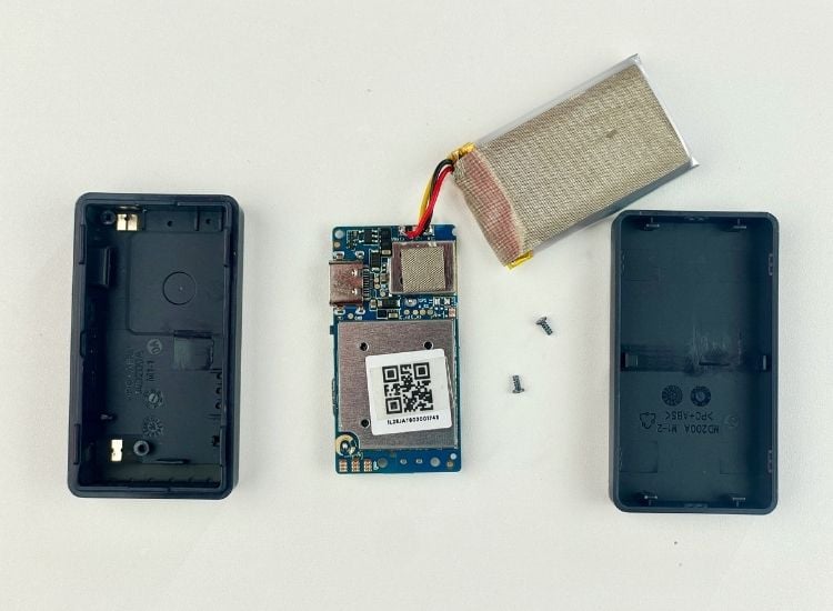
The lower half of the enclosure also integrates two adhesive-backed flexible antennas mounted directly onto the plastic housing. Each antenna connects to the main PCB through spring contacts. One of the corresponding antenna feed points on the PCB is labelled "WIFI", despite the Jio Find 4G documentation making no mention of Wi-Fi connectivity. This suggests that the PCB may be based on a common hardware platform shared across multiple products or designed to support additional wireless capabilities that might not be enabled in this particular model. Assuming the PCB silkscreen is accurate, the second antenna is likely used for LTE cellular communication.
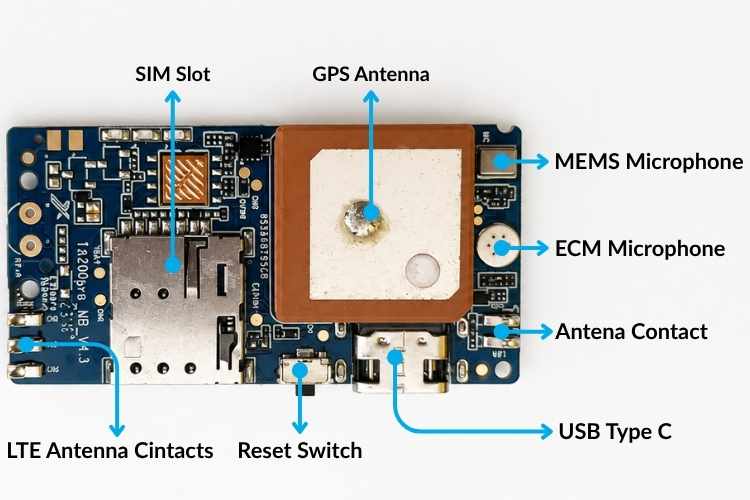
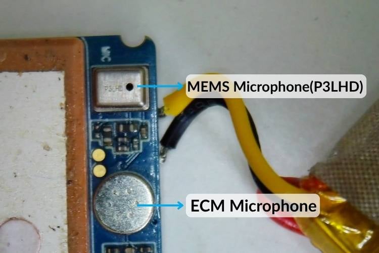
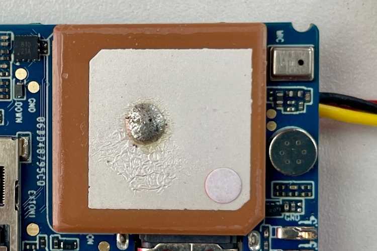
Turning the PCB over reveals several of the user-accessible components along with a few key peripherals. Most of the RF circuitry remains hidden beneath the shielding cans on the opposite side of the board, while this side primarily contains the Nano SIM card holder, GNSS antenna, MEMS microphone, ECM microphone, reset switch, and the inertial sensor used for motion detection. Occupying a significant portion of the PCB is the integrated ceramic GNSS patch antenna. It is mounted directly above the RF circuitry, minimizing feedline length and reducing signal loss between the antenna and the GNSS receiver. Adjacent to the antenna, there is a Nano SIM card holder and a small tactile reset switch. The PCB also includes two microphones, one of which is a digital MEMS microphone, identified by the package marking P3LHD, and the other is an ECM microphone. The reason for using both a MEMS and an ECM microphone is not immediately apparent. One possibility is that the design is shared across multiple product variants or that each microphone serves a different purpose, although this cannot be confirmed without schematics. These are used for the tracker's ambient voice monitoring feature.
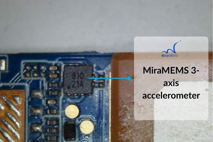
Finally, the PCB also houses an inertial sensor, which is responsible for motion detection and activity monitoring. The motion sensor appears to be a MiraMEMS 3-axis accelerometer in a compact 12-pin LGA package. Although the top-side marking (810 / 21A) does not allow the exact part number to be identified with certainty, its package and application closely match several devices from the MiraMEMS portfolio, with the DA262 being the most likely candidate. These accelerometers are designed for ultra-low-power IoT and wearable applications and integrate features such as motion detection, a FIFO buffer, and a hardware pedometer.
As mentioned earlier, most of the components on the top side of the PCB are hidden beneath two large RF shielding cans. Near the USB Type-C connector, however, there is an SOT-23-5 package marked 321BK, accompanied by a few discrete components. Based on the package marking, this IC appears to be the Runic RS321BKXF, a single rail-to-rail CMOS operational amplifier. Tracing the PCB connections suggests that it is used as a preamplifier for the ECM microphone located on the opposite side of the board, conditioning the microphone's low-level analog signal before it is processed by the main SoC. Interestingly, no dedicated battery charging IC is present on the PCB. This suggests that the charging function is likely integrated into the ASR1606 SoC.
Removing both RF shields reveals a densely populated multi-layer PCB divided into distinct functional sections. The USB Type-C interface and power management circuitry occupy one end of the board, while the RF section containing the LTE modem, GNSS receiver, RF switches, power amplifier, and associated matching networks occupies the remainder. The compact layout minimizes RF trace lengths and keeps the high-frequency signal paths well isolated. As you can see, the JioFind 4G uses both LTE and GNSS solutions from ASR Microelectronics, accompanied by dedicated RF front-end components.
The PCB uses dense component placement with short RF interconnects between the modem, power amplifier, RF switch, and antenna matching network. Ground stitching vias are distributed around the RF sections to improve shielding and provide low-impedance return paths, while the digital circuitry is concentrated near the application processor. Although the major functional ICs can be identified from their package markings and PCB layout, several smaller devices could not be positively identified because of abbreviated top markings and the limited availability of public documentation. Their functions can often be inferred from the surrounding circuitry, but their exact part numbers cannot be confirmed with certainty.
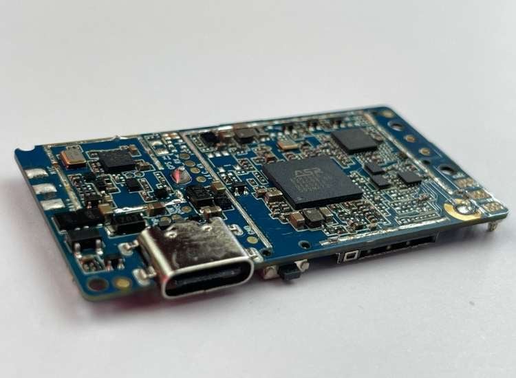
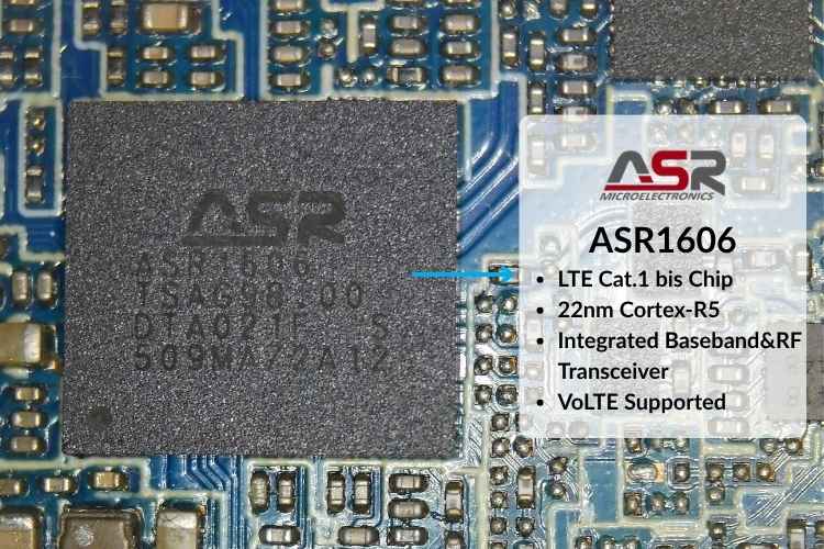
At the heart of the tracker is the ASR1606 from ASR Microelectronics, which serves as both the primary application processor and the cellular baseband modem. Fabricated using a 22 nm process and built around an Arm Cortex-R5 CPU, the chip integrates the LTE Cat.1 bis modem, application processor, memory interfaces, audio codec, PMIC, and peripheral controllers into a single package. This high level of integration minimizes the need for external components, allowing for a compact PCB design while reducing power consumption and manufacturing cost. The ASR1606 supports LTE Cat.1 bis, a cellular standard designed for low-power IoT devices that prioritize reliable connectivity, wide network coverage, and long battery life over high data throughput. Unlike conventional LTE Cat.1 solutions, Cat.1 bis requires only a single receive antenna, simplifying the RF design and further lowering hardware complexity. These characteristics make the ASR1606 well suited for compact, battery-powered products such as GPS trackers, asset monitoring devices, shared mobility equipment, smart utility meters, and other connected IoT applications. In the Jio Find 4G, it manages cellular communication, positioning, sensor processing, and overall system control. Below you can see the fully labelled diagram of the PCB Top Layer, followed by individual components of it explained in detail.
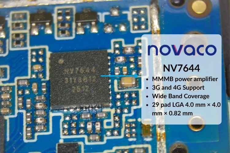
Located near the main processor is an IC marked NV7644, which has been identified as the Novaco NV7644-31, a Multimode Multiband Power Amplifier Module (PAM) designed for 3G and 4G cellular communication devices. Positioned between the ASR1606 LTE baseband processor and the RF front-end circuitry, the power amplifier increases the transmit signal to the power levels required for reliable communication with the cellular base station. The NV7644 supports a wide range of WCDMA and LTE frequency bands, allowing the same hardware platform to operate across multiple regional cellular networks. The module integrates the RF power amplifiers, impedance matching networks, and passive components into a compact 4 × 4 mm, 29-pin LGA package.
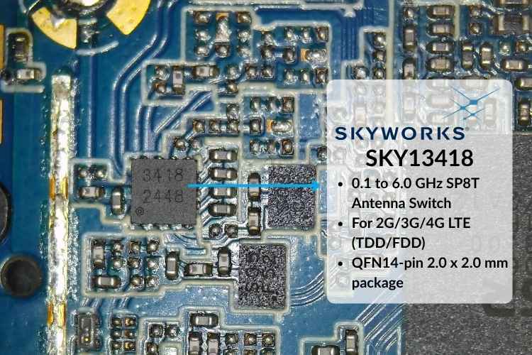
Near the 4G antenna feed line, you can locate another chip with the marking 3418. It has been identified as the Skyworks SKY13418, a high-performance RF switch used to route RF signals between the LTE modem and the external antennas. Such RF switches enable a single radio transceiver to operate efficiently across multiple frequency bands while maintaining low insertion loss and excellent isolation, both of which are essential for reliable cellular performance. The LTE transmit path consists of the ASR1606 baseband processor, the Novaco NV7644 power amplifier module, and the Skyworks SKY13418 RF switch before reaching the external antenna. During transmission, the ASR1606 generates the RF signal, the NV7644 increases the transmit power, and the SKY13418 routes the signal to the appropriate antenna path. During reception, the signal follows the reverse path back to the modem.
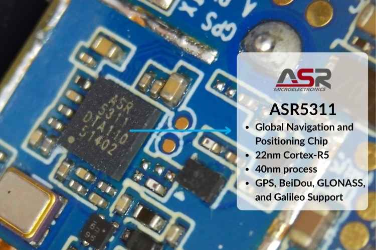
Under the small RF shielding plate is the ASR5311, a dedicated GNSS receiver from ASR Microelectronics and responsible for satellite positioning. It supports GPS, BeiDou, GLONASS, and Galileo constellations. Built on a 40 nm process, the chip delivers a high level of integration, supports multiple functions, and is designed for low-power operation. Very little public information is available about the ASR5311, just like the ASR1606, as the manufacturer has not released detailed technical documentation or datasheets to the public. Working together with the ceramic patch antenna, it provides the precise location information that forms the core functionality of the tracker. Separating the GNSS receiver from the LTE modem allows both subsystems to operate simultaneously while reducing RF interference and improving positioning performance, particularly in challenging reception environments.
A ceramic patch antenna is used for GNSS reception. It is connected to the ASR5311 GNSS receiver. The antenna occupies a significant portion of the PCB and is mounted directly above the GNSS RF section, minimizing the length of the RF feed. Unlike the LTE antennas, which are implemented as flexible FPC antennas attached to the enclosure, the GNSS antenna is soldered directly onto the PCB.
Battery Life and Location Update Interval
Jio does not officially specify the battery life or GPS location update interval for the standard JioFind on its product page or in the user manual. Although some online marketplace listings, including Amazon, advertise up to 3 days of battery life, this claim is not confirmed by Jio. During our testing, the tracker delivered approximately 2.5 days of battery life on a single charge. The test reflected typical daily use, with the device only travelling between home and the office in the morning and evening, and remaining stationary mostly for the rest of the day. Actual battery life will vary depending on factors such as movement frequency, network conditions, and GPS usage.
Jio also does not publish the GPS location update interval for the standard JioFind. However, a JioFind Pro user manual obtained from a third-party documentation website states that the device updates its GPS location approximately every 15 seconds while in motion. When stationary, it retains the last known location and reports a new position only after it has moved at least 15 meters. Since these specifications are for the JioFind Pro, they should not be assumed to apply directly to the standard JioFind, although they may provide a reasonable indication of how the tracking platform operates.
Final Thoughts
From a hardware perspective, the JioFind 4G uses a typical LTE tracker architecture centered around the ASR1606 SoC, supported by dedicated RF front-end components and a separate GNSS receiver. This keeps the PCB compact while reducing the number of external components. A few design choices are noteworthy. The presence of two microphones, a PCB antenna labelled "WIFI" despite no documented Wi-Fi support, and the lack of a dedicated battery charging IC suggest that the hardware platform may support additional features or future product variants. However, without official documentation, these remain observations rather than confirmed design details.
Although the overall hardware shares similarity that of many commercially available trackers, we were unable to identify an identical ODM or OEM design through reverse image searches or by tracing the PCB part numbers. This suggests that the Jio Find 4G is either based on a customized hardware platform or a design that is not publicly marketed under another brand. Without information from the manufacturer, its exact origin cannot be determined. During testing, the tracker delivered around 2.5 days of battery life under typical usage, which is reasonably close to the manufacturer's advertised figure. This GPS tracker teardown ultimately shows a cost-conscious, single-chip design that prioritizes compactness and battery efficiency over raw performance.

Add a comment
No account needed. Your comment appears once a moderator has reviewed it.