

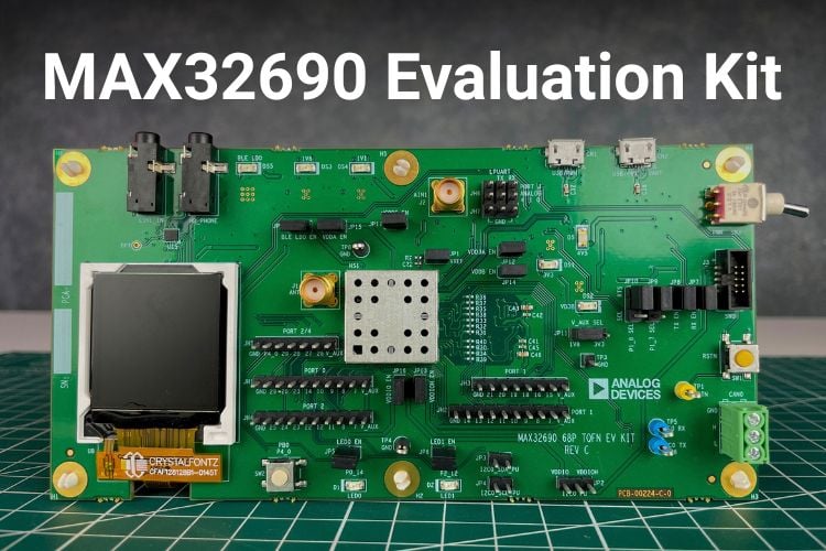
The MAX32690 evaluation kit provides a solid foundation to explore the full capabilities of the MAX32690 microcontroller, which is an advanced system-on-chip (SoC). It features an ARM Cortex-M4F CPU for efficient computation of complex functions and algorithms. It features the latest-generation Bluetooth 5 Low Energy (Bluetooth LE) radio designed for wearable and hearable fitness devices, portable and wearable wireless medical devices, industrial sensors/networks, Internet of Things (IoT), and asset tracking.
Prototyping is an important part of product development, allowing engineers to test functionality before moving to production. The MAX32690 Evaluation Kit simplifies this process by providing easy access to the microcontroller’s peripherals and several onboard features for testing and development. The GPIO, UART, and I2C pins are available through header connectors, making it easy to connect external sensors and other peripherals. The kit also includes an onboard display and audio codec, allowing developers to experiment with display- and audio-based applications without requiring additional hardware. For Bluetooth LE projects, an SMA connector is provided for connecting the included antenna. For quick prototyping, the evaluation kit features a general-purpose push button connected to GPIO P4_0, along with two general-purpose LEDs, LED0 and LED1. These onboard components can be used for testing GPIO functionality without connecting external switches or LEDs. The onboard audio codec, along with audio input and output interfaces, further expands the kit's capabilities for developing and testing audio applications.
What's Inside the MAX32690 EV Kit
The first thing to note on the PCB is that it has 6 mounting holes along the periphery and comes with white-coloured plastic mounting spacers on them. It becomes easy for mounting and prototyping. The main microcontroller, MAX32690, is given a metal shielding labelled as HS1 to reduce the RF emissions/noises that it may cause. We have GPIO pins neatly organised into different ports using 2.54 mm header pins labelled from JH1 to JH6. It becomes easy for development easier, and all of them face the top. JH6 provides access to 3 analog inputs and the UART pins LPUART_RX and LPUART_TX. We have LED indicators for BLE and different power rails. Two general-purpose LEDs are also provided for testing purposes (LED0 and LED1). The main power toggle button, SWD connector to plug in the debugger module, reset button, and the CAN Bus 2.0 terminal block sit on the right side of the PCB Top.
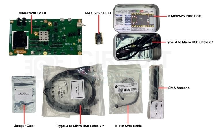
Opening up the main box, we can see all these components safely packed in individual packets. The MAX32G90 EV Kit comes in an ESD packet. The MAX32625 PICO Debugger comes in a neat metallic box with a Type-A to Micro-USB Data Cable. A hinged whip antenna is provided for Bluetooth, which can be connected to the EV Kit using the onboard SMA Connector. A 10-pin SWD connector connects the debugger module with the EV Kit for programming. Two Type-A to Micro USB Cables are provided in the box, meant for the two onboard Micro-USB Connectors seen in the MAX32690 EV Kit. Extra shunt connectors are also provided for the jumper configurations.
MAX32690 EV Kit PCB Analysis
The first thing to notice on the PCB is the six mounting holes positioned around the edges, each fitted with a white plastic spacer. These provide a convenient way to mount the board securely during development and prototyping. At the centre of the board is the MAX32690 microcontroller, covered by a metal shield marked HS1 to help reduce RF emissions and noise. The GPIO pins are neatly organised by port and brought out through 2.54 mm header pins labelled JH1 to JH6, making it easy to connect external peripherals during development. All the headers are positioned along the top edge for easy access. The JH6 header provides access to three analog inputs along with the LPUART_RX and LPUART_TX pins. The board also includes LED indicators for Bluetooth LE activity and the different power rails, along with two general-purpose LEDs, LED0 and LED1, for testing and development. On the right side of the PCB are the main power toggle switch, SWD connector for connecting a debugger, reset button, and the CAN Bus 2.0 terminal block.
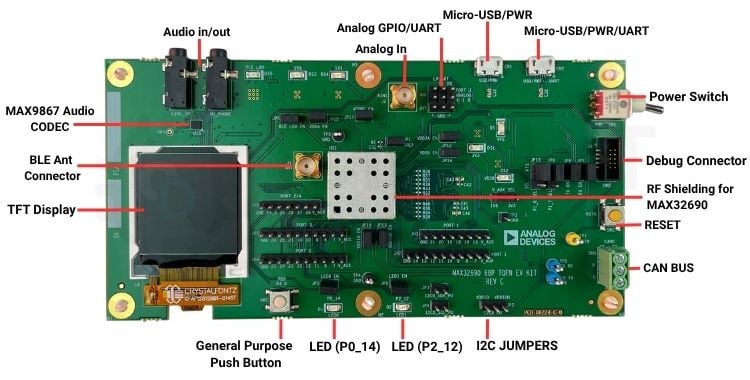
For monitoring the current drawn by each power rail, the board provides dedicated jumper points labelled JP12 to JP18. At the top of the PCB, we have 3.5 mm audio input and output connectors for audio-related applications. The audio section is built around the MAX9867EWV+T audio codec IC, located just below the connectors. The board also features two Micro-USB ports, CN1 and CN2. CN2 is typically used for programming, as it also provides access to the UART interface. To route the IC’s UART2A interface to the CN2 Micro-USB connector, jumpers JP7 to JP10 are provided. These jumpers are already fitted with jumper caps on the board.
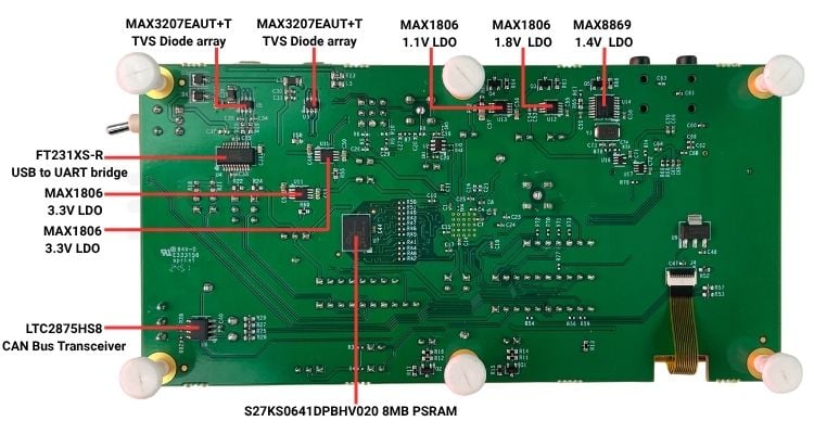
Now, let’s take a look at the PCB Bottom Layer. Several ICs and discrete components are placed on this side of the board. Let’s go through some of the major components. We have the S27KS0641DPBHV020, which is a 64 Mbit (8 MB) HyperRAM. Near the two Micro-USB ports, we can see two MAX3207EAUT+T ICs, which provide ESD protection. On the opposite side of the CAN terminal block is the LTC2875HS8, which is the CAN interface IC. Apart from these major components, the bottom layer also houses several LDOs that generate the required 1.1 V, 1.8 V, 3.3 V, and 4.5 V power rails. There is also a dedicated MAX8869EUE33 LDO that provides a stable 1.4 V supply for the Bluetooth LE subsystem.
MAX32690 EV Kit GPIOs and Jumper Settings
Let's take a look at the header pins provided on the EV Kit and explore their functions. The headers JH1, JH2, and JH4 are 10-pin, 0.1-inch headers, with the corresponding GPIO pins clearly labelled on the PCB. JH3 is an 8-pin header, while JH5 is a 7-pin header, both providing access to additional GPIO pins as marked on the board. One important header is JH6, which is a 6-pin dual-row header. It provides access to three analog inputs and the LPUART TX and RX signals, while the remaining pin is left unconnected. Finally, JH7 is a 3-pin header connected to the ground rail, providing convenient ground connections for external circuits and peripherals during development.
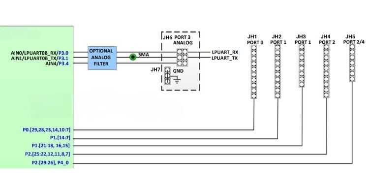
Above is the schematic from the datasheet that can be followed to identify the Headers and their functionalities.
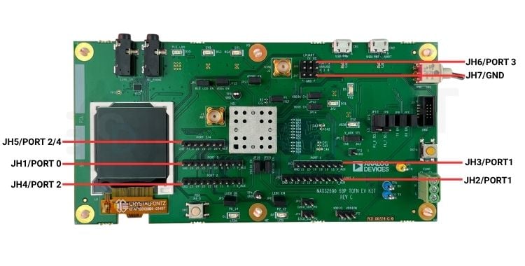
The header pin configuration on the PCB matches the schematic, and all the exposed GPIOs can be programmed according to the requirements of the application. The table below shows the MAX32690 EV Kit jumper settings that need to be followed for different configurations.
| Jumper | Name | Settings | Description |
|---|---|---|---|
| JP1 | VREF | 1-2 | Connects external voltage reference to VREF pin; must be enabled in software. For more details, see the External Voltage Reference (VREF) section. |
| Open | Disconnects external voltage reference. | ||
| JP2 | I2C0 PU | 2-1 | Connects VDDIO (1V8) to I2C0 pull-up resistors. |
| 2-3 | Connects VDDIOH (3V3) to I2C0 pull-up resistors. | ||
| Open | Disconnects power from I2C0 pull-up resistors. | ||
| JP3 | I2C0_SDA_PU | 1-2 | Connects pull-up to I2C0A_SDA (P2.7) sourced by I2C0 PU (JP2). |
| Open | Disconnects pull-up from I2C0A_SDA (P2.7) sourced by I2C0 PU (JP2). | ||
| JP4 | I2C0_SCL_PU | 1-2 | Connects pull-up to I2C0A_SCL (P2.8) sourced by I2C0 PU (JP2). |
| Open | Disconnects pull-up from I2C0A_SCL (P2.8) sourced by I2C0 PU (JP2). | ||
| JP5 | LED0 EN | 1-2 | Connects red LED D1 to P0.14. |
| Open | Disconnects red LED D1 from P0.14. | ||
| JP6 | LED1 EN | 1-2 | Connects green LED D2 to P2.12. |
| Open | Disconnects green LED D2 from P2.12. | ||
| JP7 | RX EN | 1-2 | Connects the USB-serial bridge to UART2A_RX (P1.9). |
| Open | Disconnects the USB-serial bridge from UART2A_RX (P1.9). | ||
| JP8 | TX EN | 1-2 | Connects the USB-serial bridge to UART2A_TX (P1.10). |
| Open | Disconnects the USB-serial bridge from UART2A_TX (P1.10). | ||
| JP9 | P1_7 SEL | 2-1 | Connects the USB-serial bridge to UART2A_CTS (P1.7). |
| 2-3 | Connects I2C2C_SDA (P1.7) to the codec. | ||
| JP10 | P1_8 SEL | 2-1 | Connects the USB-serial bridge to UART2A_RTS (P1.8). |
| 2-3 | Connects I2C2C_SCL (P1.8) to the codec. | ||
| JP11 | V_AUX SEL | 2-1 | Connects V_AUX to 1V8. |
| 2-3 | Connects V_AUX to 3V3. | ||
| JP12 | VDD3A EN | 1-2 | Connects 3V3 to VDD3A. |
| Open | Disconnects 3V3 from VDD3A. | ||
| JP13 | VDDIOH EN | 1-2 | Connects 3V3 to VDDIOH. |
| Open | Disconnects 3V3 from VDDIOH. | ||
| JP14 | VDDB EN | 1-2 | Connects a 3V3 LDO sourced by USB_VBUS (CN1) to VDDB. |
| Open | Disconnects a 3V3 LDO sourced by USB_VBUS (CN1) from VDDB. | ||
| JP15 | VDDA EN | 1-2 | Connects 1V8 to VDDA. |
| Open | Disconnects 1V8 from VDDA. | ||
| JP16 | VDDIO EN | 1-2 | Connects 1V8 to VDDIO. |
| Open | Disconnects 1V8 from VDDIO. | ||
| JP17 | VCORE EN | 1-2 | Connects 1V1 to VCORE. |
| Open | Disconnects 1V1 from VCORE. | ||
| JP18 | BLE LDO EN | 1-2 | Connects 1V4 to BLE_LDO. |
| Open | Disconnects 1V4 from BLE_LDO. | ||
| JH6 | ANALOG PORT3 | 1-2 | Connects LPUART0B_RX (P3.0) to the SWD connector. |
| 3-4 | Connects LPUART0B_TX (P3.1) to the SWD connector. | ||
| Open | Disconnects LPUART0B_RX (P3.0) and LPUART0B_TX (P3.1) from the SWD connector. |
Powering up MAX32690 Evaluation Kit
We will use the Micro-USB port labelled USB/PWR-UART to power the EV Kit. For debugging and programming, we will use a dedicated debugger. Once the board is connected to a laptop using the provided Micro-USB cable, some of the onboard LEDs should illuminate. We need to verify that the 4V5 blue LED (D5) and the green 3V3 (DS1), 1V8 (DS3), 1V1 (DS4), and BLE LDO (DS5) LEDs are illuminated. These LEDs indicate that the respective voltage rails are powered and operating.
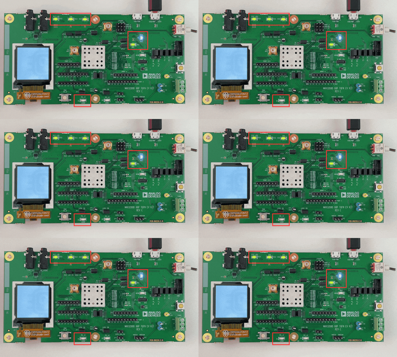
Once power is applied to the board, LED D1 automatically starts flashing, indicating that the microcontroller is running the preloaded sample code. Before moving to the next step, we need to verify the status of all six LEDs to ensure that the board is powered and operating as expected.
Programming Using Eclipse IDE
To program the MAX32690 EV Kit, we need a suitable IDE and software environment. For this tutorial, we will use the Maxim Integrated Eclipse IDE, which comes with the required tools and features for working with Maxim microcontrollers. If you already have Eclipse installed, it may not work correctly with the steps in this tutorial. We need the Eclipse IDE bundled with the MaximMicrosSDK. Let's go through the installation process. The steps are straightforward. First, visit the MAX32690 EV Kit product page and download the MaximMicrosSDK for your operating system. You will be prompted to log in. You can sign in using a Google account or create a new account and then log in. Select your operating system and download the corresponding SDK package. For this tutorial, we are using the Windows version, which is provided as the MaximMicrosSDK_win.exe installer.
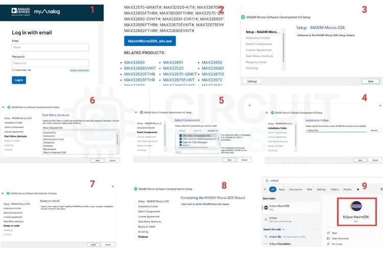
After downloading the SDK, run the installer and follow the on-screen instructions to complete the installation. Keep all the values as default unless there is a custom requirement, such as changing the default installation directory; this can be done. Once the installation is done, open the Maxim Integrated Eclipse IDE that will appear in your apps list. This Maxim Integrated Eclipse IDE is the one that we’ll be using throughout this tutorial. We will be mostly working out some example programs using this Maxim Integrated Eclipse IDE.
Creating a Project in Eclipse IDE
Creating a new project is like starting from scratch. Alternatively, we can use one of the example programs provided with the SDK as a reference and build our custom application around it. If you want to use an example project, you can import it by following the steps described in the section below. Otherwise, let's continue with creating a new project.
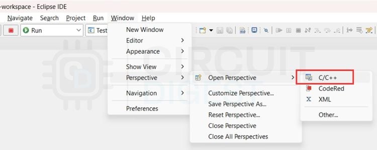
Before we can start programming or building code for the MAX32690 Evaluation Kit, we need to complete a quick initial setup. After opening the Eclipse IDE, go to Window > Perspective > Open Perspective and select C/C++ from the list. This changes the Eclipse interface to provide the tools and workspace layout required for developing C and C++ applications for the MAX32690. Once this is done, the IDE is ready for us to create a new project.
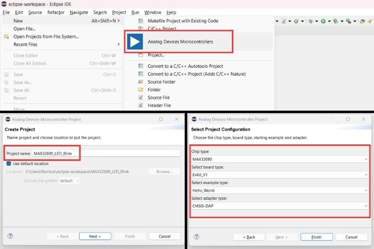
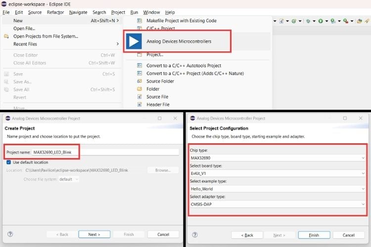
To create a new project, go to File > New > Analog Devices Microcontrollers. Give the project a name. For this tutorial, I’ve named it MAX32690_LED_Blink, as we will flash a simple LED blink program and observe the onboard LED, labelled LED0 on the PCB and connected to P0_14 of the MAX32690. Click Next to continue. A new window will open with the Project Configurations. From the drop-down menus, select the appropriate configurations as shown in the image above. The third field is the Example Type, where we can select one of the example programs provided with the kit. Here, we will select Hello_World, as it contains the basic example we need for our LED blink test. The last field is used to select the debugger or adapter. Both CMSIS-DAP and MAX32625_PICO can be used. For this tutorial, I’ve selected CMSIS-DAP. Once all the fields are configured correctly, click Finish to create the project.
Once the above steps are completed, the example main.c file will open with the code for blinking the onboard LED. However, by default, the Project Explorer, which displays the project resources and build files, may not be visible. To enable it, go to Window > Show View > Project Explorer. This will open the Project Explorer and allow us to access all the project resources.
The steps above show one way to create a workspace and start developing a program. In this tutorial, however, we will take a different approach. We will import all the examples provided with the evaluation kit at once and use them for testing. This will populate the Project Explorer with all the available example projects. This approach is similar to cloning a GitHub repository to our local system and working with the source code locally. We will use this method to build the executable files, as it makes it easier to explore and test all the examples provided with the kit.
Importing Example Programs
For this, after launching the Eclipse IDE, let's create a new Eclipse workspace where all the example code that we import will be saved.
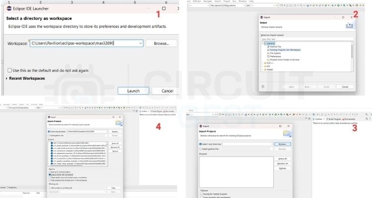
The new workspace is named max32690 and is created inside the default eclipse-workspace folder on the C drive. Once the workspace is created, instead of creating a new project as discussed earlier, right-click in the Project Explorer and select Import. In the Import window, select General > Existing Projects into Workspace. Then browse to the MAX32690 examples located at:
C:\MaximSDK\Examples\MAX32690Before clicking Finish, make sure to select Copy projects into workspace. This creates a copy of all the example projects inside our new workspace, allowing us to modify and build them without changing the original example files.
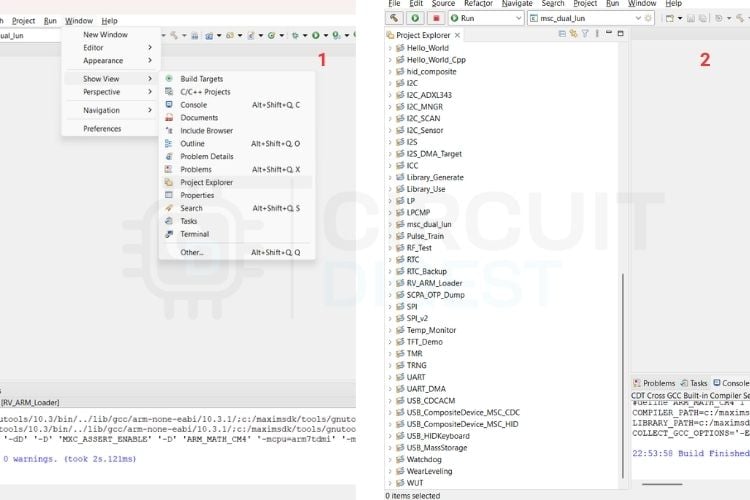
This will fill in our empty workspace’s Project Explorer section with all the example code available. If the Project Explorer doesn’t open by default, it can be enabled by going to Window > Show View > Project Explorer. This will list out all the examples in the Project Explorer.
Running Hello World
To get started with the examples, let's try to run the “Hello World” sketch that comes with the Examples. For that, let's open the main.c that comes under the project folder “Hello World”
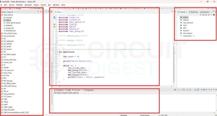
First of all, let’s try to understand the different sections that appear on the screen at this point. We have the Project Explorer that is populated with the sketches, then the Editor Window where main.c is opened right now. Below that is the console where we will be able to see all the logs. To the right side is the program Outline that lists the included files in main.c. We can open those individual files and make changes as per our requirements. We can check out these included files, keep a reference to them and build custom applications.
Flashing the program
To flash any program to the MAX32690 EV Kit, we use the MAX32625 PICO Debug Adapter, which is preloaded with the DAPLINK Software, which helps us to debug as well as flash code to the EV Kit. To set this up, connect the debugger adapter to the EV Kit using the provided SWD Cable as shown in the image below.
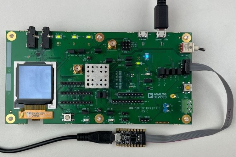
At this point, a new Disk Drive will be listed on the PC as “DAPLINK”, meaning our Debugger is properly mounted and is ready. The debugger is connected using a Micro-USB Cable that came with it, and the EV Kit is also connected to the PC using its included Micro-USB Cable at the UART Port (CN2).
Debugging
Let’s compile and debug the Hello World Program. Right-click the main folder (Hello World) and hit Clean Project just to make sure we have cleared any leftover files from the previous build. We need to do this every time we make any modifications to our code, or we need to flash updated code to the EV Kit.
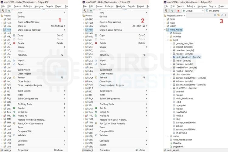
Once the Clean Project is done, let’s right-click the project and click Build Project as shown in the image above. Alternatively, the small Hammer icon on the far left can also be clicked as a shortcut to Build Project. Once that is done, if we expand the Hello World file by clicking the drop-down arrow, we can see a new folder named Build, and inside it, there is the build file / compiled program with the extension .elf. Here, the file is Hello_World.elf. We can see this in the console below as well. We can load and run this compiled program.
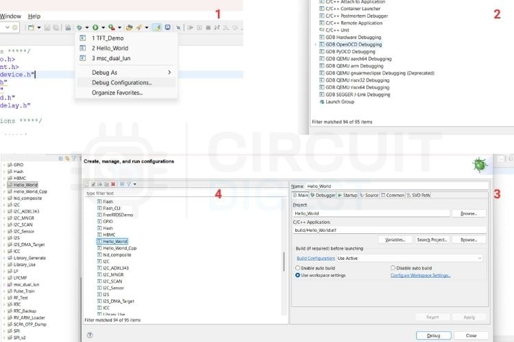
To load and run, we need to set up debug configurations. Let's learn how to set up debug configurations properly. Click the drop-down arrow next to the Bug icon > Debug Configurations > GDB OpenOCD Debugging > Hello World. Then click on Finish.
Here, whenever we are going to run an example program, set up a debug configuration for that particular program, just like we did for this Hello World Program.
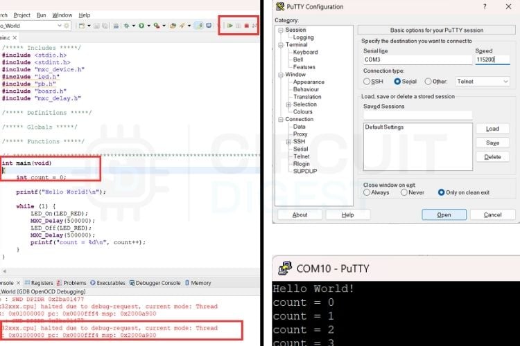
Once that’s done, we can see that our program is halted/suspended at the main() due to a debug request. To run/resume this program and see the result, all we have to do is click the play button as highlighted in the image below. The pause button pauses the program execution. To see the results in a serial window, it's recommended to use PuTTY or a Linux-based terminal. In the image below, the configurations for PuTTY are shown. Just select the correct COM port where the EC Kit is connected. The COM port can be identified in the Device Manager; it will come under the Ports(COM & LPT) section. The result of the Hello World program in PuTTY is also shown below.
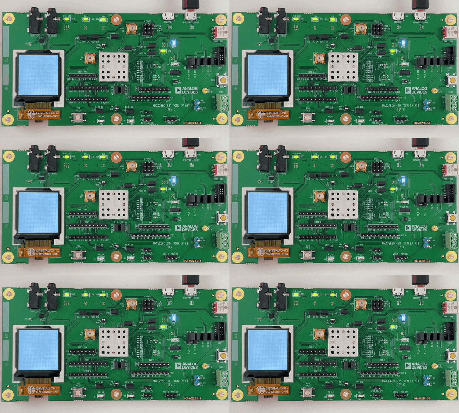
Above is the result of the Hello World program on the real hardware. These blinks in the LED0, connected to the GPIO pin PO_14, correspond to each count that is being displayed in the PuTTY window. One can modify the main.c of the Blink program to adjust the blink intervals > clean the project > build > debug again and see the changes.
TFT Demo
We have tried blinking the onboard LED. Now, let’s try something with the onboard TFT Display.
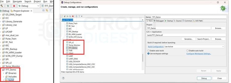
All the procedures will be the same, except this time we will be debugging the TFT Demo example program. After stopping the debugging for the Blink sketch, let's build the executable for TFT_Demo. Set the Debug Configurations for TFT_Demo and run it.
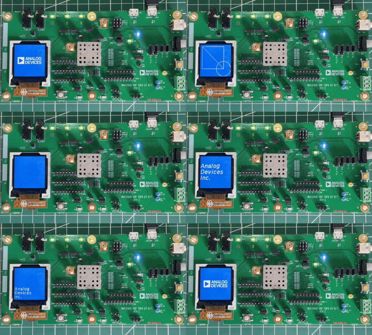
As seen in the above GIF, the inbuilt display showcases the default animation sequence, which can be altered to display some sensor values, data logs or any kind of content as per the requirements.
BLE Demo
We have tried the onboard LED Blink and tested the onboard TFT Display as well. Now, let's test the BLE functionality of this board. Since it already came with an SMA antenna, let's go ahead and try it. The procedures are the same as we did for the Blink.
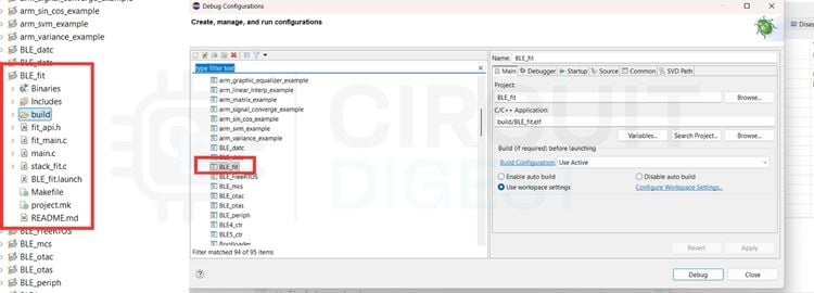
The only thing is we need to build the executable for the example program named BLE_fit. While setting up the debug configurations, we should be doing it for BLE_fit. After debugging, we need to click the small play button, the same thing that we did for the Blink and TFT Display examples. Now open PuTTY and connect to the COM port of the evaluation kit. Once we press the Reset button on the EV Kit, PuTTY will start to show some random values on the terminal. These random values are actually sample data to demonstrate the BLE functionality of the EV Kit. We can connect real sensors to the GPIOs and stream data like this in real.
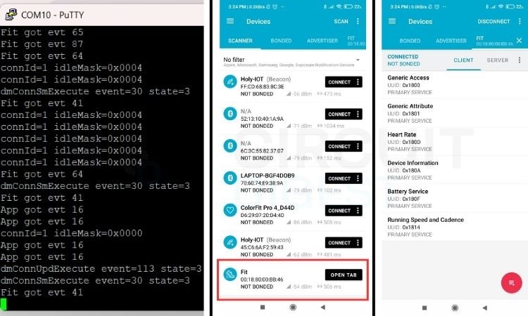
We can also see the sample data in our Bluetooth devices as well. For the demo, we are using the app nRF Connect from Nordic Semiconductor. As we click “SCAN”, we can see a BLE device named Fit is visible in the list. Once we connect to it, we will get the response in PuTTY, as well as some sample data in the nRF Connect App as well.
Programming Using VS Code
To program the MAX32690 evaluation kit in VS Code, we need to install the CodeFusion Studio extension as well as the Code Fusion supporting app.
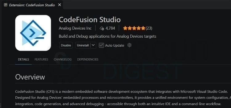
First, install the CodeFusion Studio Extension in VS Code and enable it as shown in the image. Next, the CodeFusion software can be downloaded from the official CodeFusion Studio Page; download it and install it too.
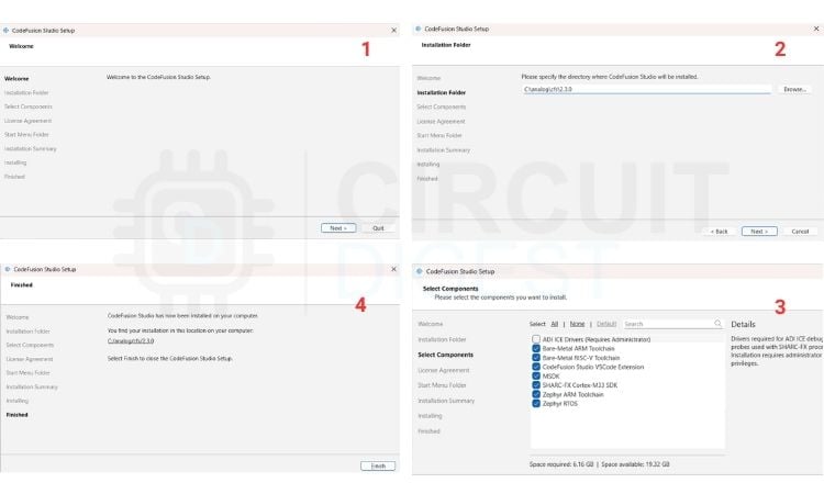
To install, just open the downloaded file, keep the default settings and follow the on-screen instructions to complete the installation. The installation folder can be modified, or you can keep it at the default location. Once it's done, continue by opening Visual Studio Code.
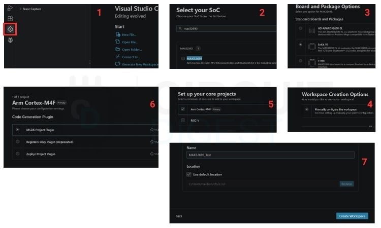
Then click on the CodeFusion icon as marked in the image to create a new workspace. Select the right SoC in the next window, then the board. Here, we are using the EvKit_V1 > Manually configure the workspace > Arm Cortex-M4F> MSDK Project Plugin > Give the workspace a name. The Workspace location can be set to a new location, or just keep the default location and hit Create Workspace.
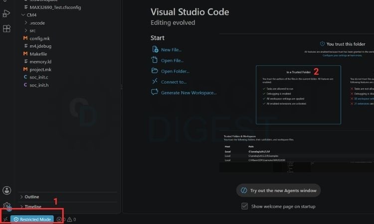
One thing to note is that whenever we create a workspace or open an example program, it will show a ‘Restricted Mode’ in the bottom-left corner. We need to click on that and hit the ‘Trust’ option for this to work.
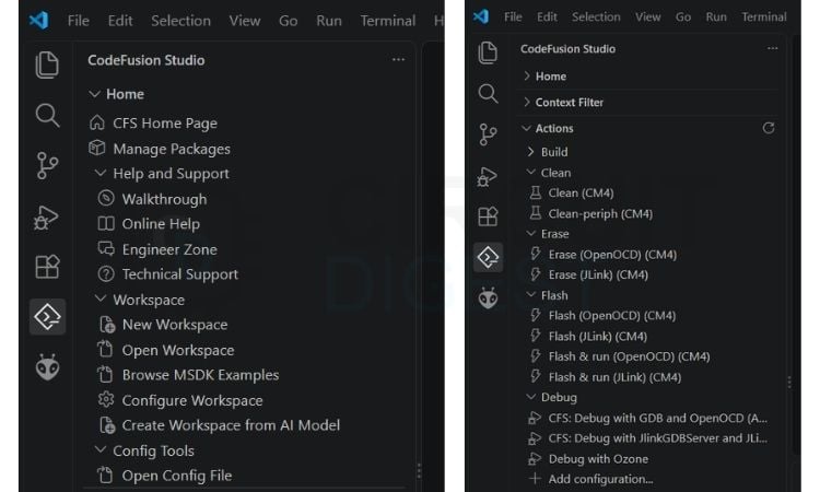
Under Home > Workspace, we have the options to create a new workspace, open a workspace, open the MSDK Examples and more. Under Actions, we can see the options to Build the executable, Clean the Build, Erase the flash memory, Flash the code and Debug. We will be working on almost all of these options. We will be using OpenOCD for debug and flash, as that’s the software bridge that is used by the MAX32625PICO SWD debug probe. Let's open an example code by clicking ‘Browse MSDK Examples’.
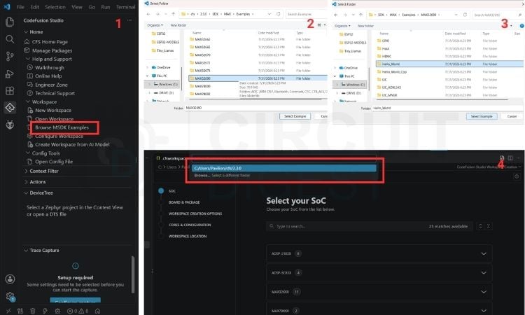
Choose the right board, select the example directory and click Select Example. It will ask for the directory where this Program should be saved. We can change it if required; otherwise, it can be kept as the default, and it will open up a copy of the selected example program.
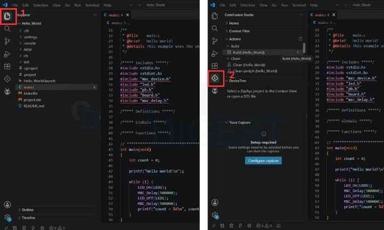
Inside the Explorer, we can see the main code, which is main.c and its associated files, and under CodeFusion Studio, we have the options to Build, Clean, Erase, Flash and Debug.
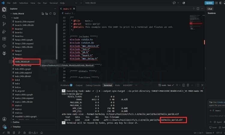
We can see that Hello_World.elf, the executable binary file, is created under the Build folder. We can modify the code as per the requirement, then Clean, Erase, Flash or Debug. Let's go ahead and start Debugging. The program execution stops at the breakpoint. But we can resume debugging using the shortcut key ‘F5’ or the option ‘CFS: Debug with GDB and OpenOCD(ARM Embedded) under Debug. It will start debugging. To stop debugging, use the keyboard shortcut ‘Shift + F5’ or the Stop icon as shown in the image.
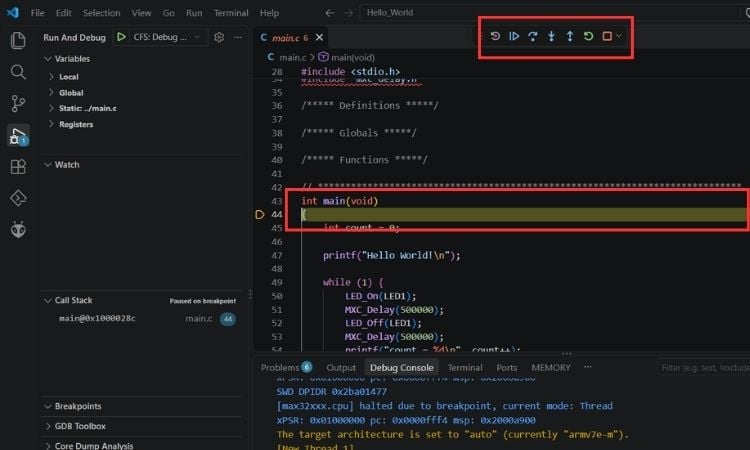
As we can see, the General Purpose LED (LED0) starts blinking. To flash the code permanently, we can use the Flash option and the code is flashed onto the microcontroller and runs whenever the board is powered. This is the exact same procedure to be followed to work with the MAX32690 Evaluation Kit for any of the examples or custom programs.
Push-Button Counter With TFT and Buzzer
Let's take a look at the code that we used for the Step Counter that displays an incrementing count on the TFT Display while audio feedback comes from the Buzzer connected to GPIO pin 26. This code was built by modifying the already provided Hello_World Example.
#define BEEP_FREQUENCY_HZ 1000
#define BEEP_DURATION_MS 60
#define BEEP_HALF_PERIOD_US (1000000 / (BEEP_FREQUENCY_HZ * 2))2))
static const mxc_gpio_cfg_t beep_pin = {
   MXC_GPIO2,
   MXC_GPIO_PIN_26,
   MXC_GPIO_FUNC_OUT,
   MXC_GPIO_PAD_NONE,
   MXC_GPIO_VSSEL_VDDIOH,
   MXC_GPIO_DRVSTR_0
};
Initially, we have all the standard C headers and the headers for MSDK defined. Here, the beep frequency is set to 1kHz and beep duration to 60ms. One complete button press cycle consists of one high half and one low half. BEEP_HALF_PERIOD_US calculates the time the GPIO stays high or low during one half-cycle. Then, the GPIO used to connect the Buzzer is defined. The first line (MXC_GPIO2) indicates Port 2, and the second line indicates GPIO Pin 26. So we are using the P2.26 for Buzzer and is configured as a digital output.
static void beep(void)
{
   const int half_cycles =
       BEEP_DURATION_MS * 1000 / (BEEP_HALF_PERIOD_US * 2);
   for (int cycle = 0; cycle < half_cycles; cycle++) {
       MXC_GPIO_OutSet(beep_pin.port, beep_pin.mask);
       MXC_Delay(MXC_DELAY_USEC(BEEP_HALF_PERIOD_US));
       MXC_GPIO_OutClr(beep_pin.port, beep_pin.mask);
       MXC_Delay(MXC_DELAY_USEC(BEEP_HALF_PERIOD_US));
   }
}
That function is the buzzer tone generator. It repeatedly drives the GPIO P2.26 pin high and low to create a square wave about 1 kHz for 60 ms, with the macro values in your program. This rapidly changing voltage makes it produce a short beep. TFT_Print and TFT-Test together print the title “SW2 Count” and the incrementing counts on each button press.
int main(void)
{
   MXC_Delay(MXC_DELAY_SEC(2));
   /* Enable cache */
   Board_Init();
   MXC_ICC_Enable(MXC_ICC0);
   /* Set system clock to 100 MHz */
   MXC_SYS_Clock_Select(MXC_SYS_CLOCK_IPO);
   SystemCoreClockUpdate();
   /* Initialize TFT display */
   MXC_TFT_Init();
   MXC_GPIO_Config(&beep_pin);
   MXC_GPIO_OutClr(beep_pin.port, beep_pin.mask);
   TFT_test();
   return 0;
}
The main() starts by waiting two seconds, giving the MAX32690EVKIT and its peripherals time to stabilize after power-up. It initializes the board, enables the instruction cache for faster code execution, selects the internal precision oscillator as the system-clock source, and updates the software clock value used by timing routines. Next, it initializes the onboard TFT display and configures GPIO P2.26 as the buzzer output, setting it low so the buzzer is silent at startup. Finally, it calls TFT_test(), which continuously reads SW2, updates the on-screen press count, and produces a short beep after each press.
Result
Below is the result of the Step Counter Program.
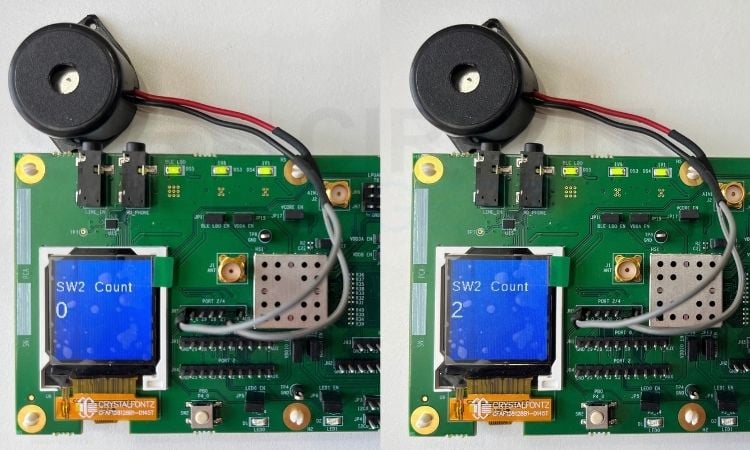
When powered on, the SW2 Count will be zero, and as we press the General Purpose Button SW2, the count gets incremented by one with a beep sound from the buzzer. To reset the counter, the Reset button (RSTIN) can be used. This can be considered the perfect starting point to get started with the MAX32690 Evaluation Kit.
GitHub Repository



Add a comment
No account needed. Your comment appears once a moderator has reviewed it.