

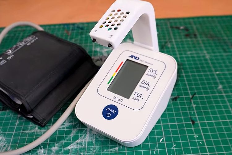
Smart blood pressure monitors that sync to an app usually cost more than plain ones, and many push your readings into somebody else's cloud account. Tomasz Burzy of Mellow_Labs wanted his readings in his own self-hosted health tracker instead, so he kept a basic A&D UA-611 monitor and taught it Wi-Fi from the outside. An ESP32-CAM on a 3D-printed arm looks at the LCD, reads systolic, diastolic and pulse straight off the seven-segment digits, and sends each new result over Wi-Fi to Home Assistant, Node-RED or any server. No wire goes into the monitor's measuring circuit.
Why tapping the circuit did not work
His first plan was the obvious one: open the monitor and sniff the data. With a cheap logic analyser he found a test point carrying the raw pressure sensor value, and he even wrote his own code to turn that into a blood pressure estimate. It came close, but it never matched the number on the screen, because these monitors use their own undisclosed algorithm to work out the final values from the cuff pressure curve.
Catching the finished numbers on their way to the display was not possible either. In this unit one chip does almost everything, including driving the LCD, so there is no bus between a processor and a display driver to listen to.
Reading the screen without machine vision
So he pointed a camera at the display. The neat part is that the ESP32-CAM does not run any OCR or neural network. The camera and the monitor never move relative to each other, so every LCD segment always lands on the same pixels. A small Python tool, the digit mapper, lets you drag a box over each digit on one saved frame. From then on the ESP32 only checks whether a fixed set of points is dark or light and turns that pattern into numbers.
The project on GitHub is split into three steps:
- Camera preview: a live view in the browser to fix the camera square-on and save one frame
- Digit mapper: mark the SYS, DIA and PULSE digits and tune the "lit" threshold per row
- Reader: the final sketch that reads each result and sends it to a URL you choose, with optional buttons to tell family members apart
The camera arm STEP file is included, but it is shaped for the UA-611, so other monitors will need the arm adapted and the digits mapped again.
Our take
This is a good lesson in picking the boundary of a hack. When a cheap device keeps its secrets inside one chip, the display is the cleanest interface you have, and a fixed camera with a calibrated map is far simpler than real OCR. The same idea will work for old energy meters, weighing scales or any appliance with a segment LCD. If you want to start with the board itself, our ESP32-CAM object detection project covers capturing and sending frames from the same module.
Image credit: Mellow_Labs (YouTube), cropped and resized.
About the author: Aswinth Raj is an electronics engineer and the editor of CircuitDigest, where he has published more than 150 hands-on projects and tutorials across Arduino, PIC, ESP32, Raspberry Pi and EV battery systems. He selects the stories on this page for what engineers and makers can actually learn or build from. Connect on LinkedIn

Add a comment
No account needed. Your comment appears once a moderator has reviewed it.