Vehicle Tracking systems are very commonly used in fleet management and asset tracking applications. Today these systems can not only track the location of the vehicle but can also report the speed and even control it remotely. In general, tracking of vehicles is a process in which we track the vehicle location in form of Latitude and Longitude (GPS coordinates). GPS Coordinates are the value of a location. This system is very efficient for outdoor application purposes. This kind of Vehicle Tracking System Project is widely in tracking Cabs/Taxis, stolen vehicles, school/college buses, etc.In this project, we are going one step ahead with GPS building a GSM and GPS based vehicle tracking system using Arduino. This Vehicle Tracking System can also be used to track a vehicle using GPS and GSM and can also be used as Accident Detection Alert System, Soldier Tracking System and many more, by just making few changes in hardware and software.
We have also build many other types of vehicle tracking systems previously, you can check them out if interested
- GPS Vehicle Tracking and Accident Alert using Arduino
- Vehicle Tracking with Google Maps using Arduino and ESP8266
- GPS Vehicle Tracking and Accident Alert using MSP430
- LoRa based GPS Vehicle Tracking using Arduino
- Location Tracker without GPS using SIM800 and Arduino
Components Required for Arduino based Vehicle Tracking system:
To build a simple vehicle tracking system suing Arduino we will need the following components.
- Arduino UNO
- GSM Module
- GPS Module
- 16x2 LCD
- Power Supply
- Connecting Wires
- 10 K POT
How can GSM Module be used to track location:
GPS stands for Global Positioning System and used to detect the Latitude and Longitude of any location on the Earth, with exact UTC time (Universal Time Coordinated). GPS module is the main component in our vehicle tracking system project. This device receives the coordinates from the satellite for each and every second, with time and date.
GPS module sends the data related to tracking position in real time, and it sends so many data in NMEA format (see the screenshot below). NMEA format consist several sentences, in which we only need one sentence. This sentence starts from $GPGGA and contains the coordinates, time and other useful information. This GPGGA is referred to Global Positioning System Fix Data. Know more about Reading GPS data and its strings here.
We can extract coordinate from $GPGGA string by counting the commas in the string. Suppose you find $GPGGA string and stores it in an array, then Latitude can be found after two commas and Longitude can be found after four commas. Now these latitude and longitude can be put in other arrays.
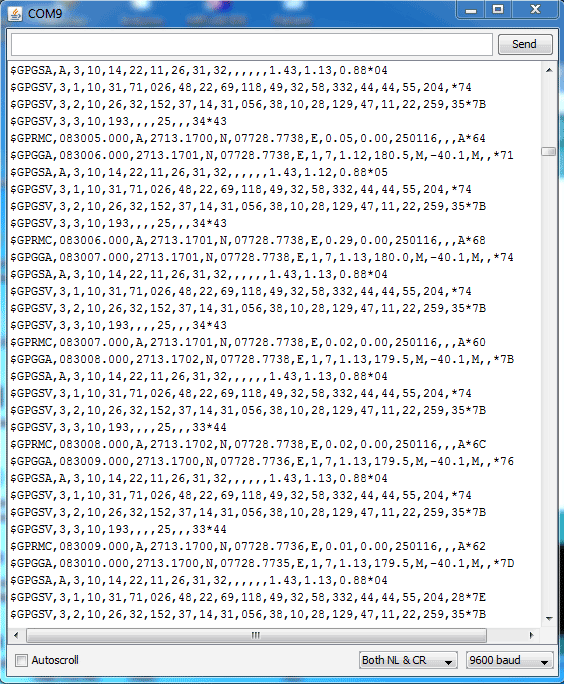
Below is the $GPGGA String, along with its description:
$GPGGA,104534.000,7791.0381,N,06727.4434,E,1,08,0.9,510.4,M,43.9,M,,*47
$GPGGA,HHMMSS.SSS,latitude,N,longitude,E,FQ,NOS,HDP,altitude,M,height,M,,checksum data
Identifier | Description |
$GPGGA | Global Positioning system fix data |
HHMMSS.SSS | Time in hour minute seconds and milliseconds format. |
Latitude | Latitude (Coordinate) |
N | Direction N=North, S=South |
Longitude | Longitude(Coordinate) |
E | Direction E= East, W=West |
FQ | Fix Quality Data |
NOS | No. of Satellites being Used |
| HPD | Horizontal Dilution of Precision |
Altitude | Altitude from sea level |
M | Meter |
Height | Height |
Checksum | Checksum Data |
Circuit Explanation for Interfacing GSM and GPS with Arduino:
Circuit Connections of this Vehicle Tracking System Project is simple and is shown in the image belwo. Here Tx pin of GPS module is directly connected to digital pin number 10 of Arduino. By using Software Serial Library here, we have allowed serial communication on pin 10 and 11, and made them Rx and Tx respectively and left the Rx pin of GPS Module open. By default Pin 0 and 1 of Arduino are used for serial communication but by using SoftwareSerial library, we can allow serial communication on other digital pins of the Arduino. 12 Volt supply is used to power the GPS Module.
![]()
GSM module’s Tx and Rx pins of are directly connected to pin Rx and Tx of Arduino. GSM module is also powered by 12v supply. An optional LCD’s data pins D4, D5, D6 and D7 are connected to pin number 5, 4, 3, and 2 of Arduino. Command pin RS and EN of LCD are connected with pin number 2 and 3 of Arduino and RW pin is directly connected with ground. A Potentiometer is also used for setting contrast or brightness of LCD.
GSM and GPS based Vehicle Tracking system using Arduino - Working
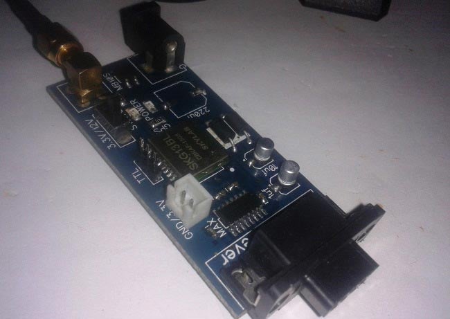
In this project, Arduino is used for controlling whole the process with a GPS Receiver and GSM module. GPS Receiver is used for detecting coordinates of the vehicle, GSM module is used for sending the coordinates to user by SMS. And an optional 16x2 LCD is also used for displaying status messages or coordinates. We have used GPS Module SKG13BL and GSM Module SIM900A.
![]()
When we ready with our hardware after programming, we can install it in our vehicle and power it up. Then we just need to send a SMS, “Track Vehicle”, to the system that is placed in our vehicle. We can also use some prefix (#) or suffix (*) like #Track Vehicle*, to properly identify the starting and ending of the string, like we did in these projects: GSM Based Home Automation and Wireless Notice Board
Sent message is received by GSM module which is connected to the system and sends message data to Arduino. Arduino reads it and extract main message from the whole message. And then compare it with predefined message in Arduino. If any match occurs then Arduino reads coordinates by extracting $GPGGA String from GPS module data (GPS working explained above) and send it to user by using GSM module. This message contains the coordinates of vehicle location.
GAM and GPS Interfacing with Arduino Code to Track Vehicle Location
In programming part first we include libraries and define pins for LCD & software serial communication. Also define some variable with arrays for storing data. Software Serial Library is used to allow serial communication on pin 10 and 11.
#include<LiquidCrystal.h>
LiquidCrystal lcd(7, 6, 5, 4, 3, 2);
#include <SoftwareSerial.h>
SoftwareSerial gps(10,11); // RX, TX
char str[70];
String gpsString="";
... ....
.... ....
Here array str[70] is used for storing received message from GSM module and gpsString is used for storing GPS string. char *test=”$GPGGA” is used to compare the right string that we need for coordinates.
After it we have initialized serial communication, LCD, GSM & GPS module in setup function and showed a welcome message on LCD.
void setup()
{
  lcd.begin(16,2);
  Serial.begin(9600);
  gps.begin(9600);
  lcd.print("Vehicle Tracking");
  lcd.setCursor(0,1);
  ... ....
  .... ....
In loop function we receive message and GPS string.
void loop()
{
  serialEvent();
  if(temp)
  {
    get_gps();
    tracking();
  }
}
Functions void init_sms and void send_sms() are used to initialising and sending message. Use proper 10 digit Cell phone no, in init_sms function.
Function void get_gps() has been used to extract the coordinates from the received string.
Function void gpsEvent() is used for receiving GPS data into the Arduino.
Function void serialEvent() is used for receiving message from GSM and comparing the received message with predefined message (Track Vehicle).
void serialEvent()
{
  while(Serial.available())
  {
    if(Serial.find("Track Vehicle"))
    {
      temp=1;
      break;
    }
    ... ....
    .... ...
Initialization function ‘gsm_init()’ is used for initialising and configuring the GSM Module, where firstly, GSM module is checked whether it is connected or not by sending ‘AT’ command to GSM module. If response OK is received, means it is ready. System keeps checking for the module until it becomes ready or until ‘OK’ is received. Then ECHO is turned off by sending the ATE0 command, otherwise GSM module will echo all the commands. Then finally Network availability is checked through the ‘AT+CPIN?’ command, if inserted card is SIM card and PIN is present, it gives the response +CPIN: READY. This is also check repeatedly until the network is found. This can be clearly understood by the Video below.
Check all the above functions in Code Section below.
Complete Project Code
#include<LiquidCrystal.h>
LiquidCrystal lcd(7, 6, 5, 4, 3, 2);
#include <SoftwareSerial.h>
SoftwareSerial gps(10,11); // RX, TX
//String str="";
char str[70];
String gpsString="";
char *test="$GPGGA";
String latitude="No Range      ";
String longitude="No Range     ";
int temp=0,i;
boolean gps_status=0;
void setup()
{
  lcd.begin(16,2);
  Serial.begin(9600);
  gps.begin(9600);
  lcd.print("Vehicle Tracking");
  lcd.setCursor(0,1);
  lcd.print("    System      ");
  delay(2000);
  gsm_init();
  lcd.clear();
  Serial.println("AT+CNMI=2,2,0,0,0");
  lcd.print("GPS Initializing");
  lcd.setCursor(0,1);
  lcd.print("  No GPS Range  ");
  get_gps();
  delay(2000);
  lcd.clear();
  lcd.print("GPS Range Found");
  lcd.setCursor(0,1);
  lcd.print("GPS is Ready");
  delay(2000);
  lcd.clear();
  lcd.print("System Ready");
  temp=0;
}
void loop()
{
  serialEvent();
  if(temp)
  {
    get_gps();
    tracking();
  }
}
void serialEvent()
{
  while(Serial.available())
  {
    if(Serial.find("Track Vehicle"))
    {
      temp=1;
      break;
    }
    else
    temp=0;
  }
}

void gpsEvent()
{
  gpsString="";
  while(1)
  {
   while (gps.available()>0)            //checking serial data from GPS
   {
    char inChar = (char)gps.read();
     gpsString+= inChar;                    //store data from GPS into gpsString
     i++;
     if (i < 7)
     {
      if(gpsString[i-1] != test[i-1])         //checking for $GPGGA sentence
      {
        i=0;
        gpsString="";
      }
     }
    if(inChar=='\r')
    {
     if(i>65)
     {
       gps_status=1;
       break;
     }
     else
     {
       i=0;
     }
    }
  }
   if(gps_status)
    break;
  }
}

void gsm_init()
{
  lcd.clear();
  lcd.print("Finding Module..");
  boolean at_flag=1;
  while(at_flag)
  {
    Serial.println("AT");
    while(Serial.available()>0)
    {
      if(Serial.find("OK"))
      at_flag=0;
    }

    delay(1000);
  }
  lcd.clear();
  lcd.print("Module Connected..");
  delay(1000);
  lcd.clear();
  lcd.print("Disabling ECHO");
  boolean echo_flag=1;
  while(echo_flag)
  {
    Serial.println("ATE0");
    while(Serial.available()>0)
    {
      if(Serial.find("OK"))
      echo_flag=0;
    }
    delay(1000);
  }
  lcd.clear();
  lcd.print("Echo OFF");
  delay(1000);
  lcd.clear();
  lcd.print("Finding Network..");
  boolean net_flag=1;
  while(net_flag)
  {
    Serial.println("AT+CPIN?");
    while(Serial.available()>0)
    {
      if(Serial.find("+CPIN: READY"))
      net_flag=0;
    }
    delay(1000);
  }
  lcd.clear();
  lcd.print("Network Found..");
  delay(1000);
  lcd.clear();
}
void get_gps()
{
   gps_status=0;
   int x=0;
   while(gps_status==0)
   {
    gpsEvent();
    int str_lenth=i;
    latitude="";
    longitude="";
    int comma=0;
    while(x<str_lenth)
    {
      if(gpsString[x]==',')
      comma++;
      if(comma==2)        //extract latitude from string
      latitude+=gpsString[x+1];
      else if(comma==4)        //extract longitude from string
      longitude+=gpsString[x+1];
      x++;
    }
    int l1=latitude.length();
    latitude[l1-1]=' ';
    l1=longitude.length();
    longitude[l1-1]=' ';
    lcd.clear();
    lcd.print("Lat:");
    lcd.print(latitude);
    lcd.setCursor(0,1);
    lcd.print("Long:");
    lcd.print(longitude);
    i=0;x=0;
    str_lenth=0;
    delay(2000);
   }
}
void init_sms()
{
  Serial.println("AT+CMGF=1");
  delay(400);
  Serial.println("AT+CMGS=\"+91**********\"");   // use your 10 digit cell no. here
  delay(400);
}
void send_data(String message)
{
  Serial.println(message);
  delay(200);
}
void send_sms()
{
  Serial.write(26);
}
void lcd_status()
{
  lcd.clear();
  lcd.print("Message Sent");
  delay(2000);
  lcd.clear();
  lcd.print("System Ready");
  return;
}
void tracking()
{
    init_sms();
    send_data("Vehicle Tracking Alert:");
    send_data("Your Vehicle Current Location is:");
    Serial.print("Latitude:");
    send_data(latitude);
    Serial.print("Longitude:");
    send_data(longitude);
    send_data("Please take some action soon..\nThankyou");
    send_sms();
    delay(2000);
    lcd_status();
}
Comments
I have connected everything as given everything powers up nice but the nothing is shown in the display ?
but the display is lighting up ?
any problem in the connections can anyone suggest a solution?
I sent a Track Vehicle msg to that sim but it is not giving Location coordinates after intilizating of gps what was the problem can u please help me
I don't need lcd dispaly
which part i should remove the program
..
and also can i upload this program to pro mini ,is there any changes to be made...!!
Brutforce way: Just remove the LCD from the hardware and everything will work just fine
hello, sir i want to track vehicle on turn and to inform user about the vehicle on turn. similarly i want to display it on graphical display continuously to show the exact location of vehicle. so can it is possible using GPS or i required any sensor?
I have my final project with many interfaces using arduino mega 2560
please can i have the code for the same project without using lcd display?
Sir I have done this connection and feed the given in ardino but if I send a msg Track Vehicle there is no response to me
With lat and long vali ...
Please help me sir
I am using neo 6m 0001 gps module and gsm sim300 module and upload the same program but the latitude and longitude value not shown please give me some guidelines
RESP SIR I HAVE MAKE THIS PROJECT FROM YOUR SIDE AT HOME.BUT MESSAGE REPLY WILL NOT COME SO PLEASE SEND THE ACTUAL CODE ON MY EMAIL ID.THIS IS MY FINAL YEAR PROJECT .
I have tried your code in arduino, but i haven't seen the location in the maps.
How to solve this....
my own gps car tracker shows me
'initializing no gps range'
i have my final project. i have used SIM800A and gps GY-GPS6MV2 , and i just want to track lattitudeand longitude and send it to particular no., can anyone send me code for that, this code is not working with GSM800A module, wt to u..
if i am using sim808 gsm+gps molude what are the modification code.
plzzz help me as soon as possible
I use sim800l . And every thing works fine . The LCD shows up SYSTEM READY . But whenever i send a message the serial monitor shows AT+CMGD=1,4 repeatedly. so kindly someone help....
Can we use GSM SIM800A with arduino UNO r3 for vehicle tracking
most helpfull
How to connect into google maps to see the vehicle where is the exact position?
Badly need your help.plsss respect
Sir good day. How to connect into google maps?
yes i had this type of problem ,,how can i solve
Thank you for this post. I have make it . Everything is going well except one thing. The message "disabling echo" is stuck on the lcd. I am using arduino uno,sim900D GSM, module with compass.
Sir mera GPS 6m use kiya hai toh uski coding change krni pada gi kya
Can someone tell me where the GSM pin must be in the code.
These are four numbers, but can not find where in the code.
Hello
I am getting
AT
AT
ATE0
AT+CPIN?
AT+CPIN?
only showing this one in serial monitor lcd is also not showing any message
Plz resolve this issue

yes you can