
Building a real-time GPS tracker with Raspberry Pi Pico has never been more accessible thanks to affordable cellular communication modules and simplified programming libraries. This comprehensive Raspberry Pi Pico GPS tracker tutorial demonstrates how to create a professional-grade IoT tracking device using the SIM800L GSM module, Neo 6M GPS module with Raspberry Pi, and the versatile Raspberry Pi Pico microcontroller, similar to our ESP32 GPS Tracker and Arduino GPS Tracker that we have built earlier. This DIY GPS tracking system transmits precise location data over cellular networks, enabling real-time location monitoring from anywhere worldwide with minimal hardware investment.
This complete Raspberry Pi Pico GPS Tracker tutorial covers hardware setup, from circuit wiring and power management to real-time location data transmission. It is tailored for hobbyists, engineers, and educators looking to implement real-time location tracking in their IoT projects. Also, if you're interested in exploring more about Raspberry Pi projects, be sure to check out CircuitDigest. We have previously covered a lot of Raspberry Pi Pico and Raspberry Pi Zero Projects.
Real-Time GPS Tracker with Raspberry Pi Pico - Quick Overview
Build Time: 4-6 hours | Cost: $30-50 | Difficulty: Beginner-Intermediate
What You'll Learn: UART communication, GPS data parsing, GSM/HTTP transmission, and Offline data buffering
Applications: Vehicle tracking, Asset monitoring, Pet locator, Delivery logistics 4.1s
Table of Contents
Required Components for Raspberry Pi Pico GPS Tracker
Warning: SIM800L is sensitive to voltage and requires a 3.7V - 4.2V regulated supply with sufficient current (~2A peak). If your module doesn't have a built-in regulator(LDO), always use a LiPo or a separate buck converter.
How Does the Raspberry Pi Pico GPS Tracker Work?
In this cellular GPS tracker with Raspberry Pi Pico project, we are building a compact and efficient GPS tracker that’s easy to implement both in hardware and software. At the core of the system is the Raspberry Pi Pico, a cost-effective microcontroller that coordinates data collection and transmission. For location tracking, we use the Neo-6M GPS module, which provides real-time latitude and longitude data via GPS satellites. To send this data to the cloud, we rely on the SIM800L GSM module, which transmits information over a cellular network using simple HTTP requests.
![]()
On the software side, the tracker integrates with the GeoLinker API, developed by Circuit Digest Cloud. This API allows us to easily send GPS data to a cloud server, where each location point is logged in a database and displayed on an interactive map. Once you log into your Circuit Digest Cloud account, you can view the plotted route in real time, giving you a live view of the tracker’s movements.
One of the standout features of this system is its ability to handle internet connectivity issues gracefully. When the cellular connection is lost, the tracker temporarily stores GPS data locally in a buffer. As soon as the connection is restored, the stored data is uploaded first, followed by any newly captured points. This ensures that no location data is lost, even when operating in areas with poor or intermittent network coverage. Overall, this makes the Pico GPS tracker a reliable solution for real-time location tracking with built-in fault tolerance.
Understanding SIM800L and Neo-6M GPS Modules
SIM800L GSM/GPRS Module
The SIM800L is a low-cost GSM/GPRS module designed for IoT tracking devices and embedded GPS solutions, making it ideal for DIY location monitoring projects. It operates on quad-band frequencies (850, 900, 1800, and 1900 MHz), making it compatible with 2G networks worldwide. Its small form factor and UART-based communication make it ideal for microcontroller integration.
Key Features and Capabilities
⇒ Voice, SMS, and GPRS Data: The SIM800L can make and receive voice calls, send and receive SMS messages, and connect to the internet using GPRS. This makes it versatile for remote monitoring and alert-based systems.
⇒ TCP/UDP and HTTP Support: It supports TCP/IP stack and HTTP via AT commands, enabling interaction with web APIs or cloud databases.
⇒ AT Command Control: Controlled entirely via AT commands over UART. It responds to common commands like AT, AT+CSQ, AT+CREG?, AT+HTTPACTION, etc.
⇒ Low Power Modes: Offers various power-saving options, including sleep and idle states, for battery-powered projects.
⇒ Network Functions: Can scan for available networks, handle automatic or manual network registration, and report signal quality.
Hardware Considerations
⇒ Voltage Sensitivity: It must be powered with a stable supply of 3.7V to 4.2V, and it can draw up to 2A of current during transmission bursts.
⇒ Antenna: Requires an external GSM antenna for proper signal strength. Antenna types include PCB, helical, or SMA-based external ones.
⇒ Logic Levels: Operates at 2.8V to 3V logic level, but in our testing, it was able to withstand 3.3V on MCU Pins. Use a level shifter if you are using a standalone SIM800L IC.
Neo 6M GPS Module with Raspberry Pi
The Neo-6M is a compact and cost-effective GPS receiver module developed by u-blox, designed specifically for tracking and navigation applications. It supports only the GPS (Global Positioning System) constellation. The setup() function initialises both UART interfaces for the Neo 6M GPS module with Raspberry Pi communication and SIM800L cellular connectivity.
The module is popular for its low power consumption, high positioning accuracy, and fast time-to-first-fix (TTFF). It communicates using standard NMEA 0183 sentences over a UART interface, typically at a default baud rate of 9600 bps. Due to its reliability and affordability, it's widely used in vehicle tracking systems, drones, robotics, and DIY navigation devices.
Key Features and Capabilities
⇒ NMEA 0183 Protocol Output: Continuously transmits GPS data such as time, latitude, longitude, altitude, number of satellites, speed, and fix quality via standard NMEA sentences like $GPGGA, $GPRMC, $GPGSV, and others.
⇒ High Sensitivity Receiver: Capable of acquiring weak satellite signals (-161 dBm tracking sensitivity), making it suitable for outdoor use with minimal obstruction.
⇒ Fast Time-to-First-Fix (TTFF): Supports hot, warm, and cold starts with TTFF as low as 1 second (hot) and 27 seconds (cold).
⇒ Position Accuracy: Offers 2.5m CEP positioning accuracy under clear sky conditions.
⇒ Backup Battery Support: Can be equipped with a coin cell to retain satellite data and RTC for faster startups.
Hardware Considerations
⇒ Antenna Requirements: Works best with an active GPS antenna for improved signal acquisition. Typically includes a UFL or SMA connector.
⇒ Power Supply: IC Operates at 3.3V and draws around 45–50 mA. Avoid powering from 5V directly if your module doesn't have a power regulator(LDO).
⇒ Status LED: Blinks when the module has acquired a valid fix, providing easy visual feedback.
Raspberry Pi Pico GPS Tracker Circuit Diagram & Wiring Guide
Note: Ensure that both the SIM800L and Neo-6M share a common ground with the Pico. Also, if your SIM800L & Neo-6M Modules have an inbuilt regulator(LDO), you can connect VCC directly to the 5V or VBUS pin in Pico.
Setting Up CircuitDigest Cloud & GeoLinker API
CircuitDigest Cloud is a powerful IoT and AI integration platform designed to support developers, engineers, and makers in rapidly prototyping and deploying intelligent embedded systems. It offers a suite of web-based services and APIs that simplify the process of adding connectivity, data visualisation, and intelligent automation to microcontroller and IoT projects.

Among its key offerings is the GeoLinker API, a cloud-based data ingestion and visualisation service specifically designed for GPS/GNSS-based devices. CircuitDigest Cloud also includes additional RESTful APIs such as QR Code Scanning, Automatic Number Plate Recognition, and SMS API, enabling seamless expansion into computer vision, authentication, and notification systems. These features allow users to build comprehensive IoT ecosystems from a single, unified interface.
Visualising GPS Data using GeoLinker
To begin using the GeoLinker API for real-time GPS data tracking and map visualisation, users must first register for an account on CircuitDigest Cloud and generate a unique API Key. This API Key acts as a secure authentication token, linking your embedded device (e.g., Raspberry Pi Pico) with the cloud backend. The process is simple and requires only a few steps:
Go to the official CircuitDigest Cloud website at https://circuitdigest.cloud. and in the top right corner, click Sign in.
If you are new to CircuitDigest Cloud, you need to register a new account by following the steps below.
Registering a New Account in Circuit Digest Cloud
⇒ Step 1:
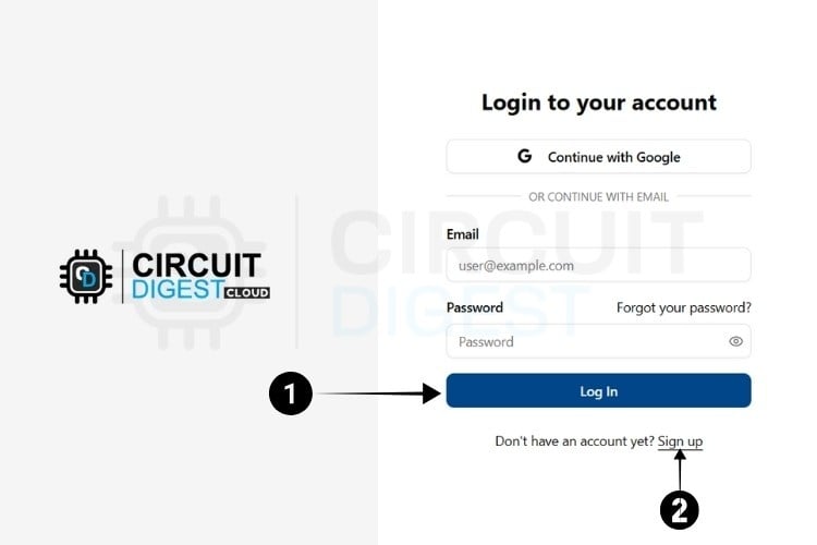
Visit the Circuit Digest. Cloud Home Page. Click the "Login" button located at the bottom, which redirects to the login page.
⇒ Step 2:
If you already have an account, log in using your existing credentials. If not, go to the registration page to create an account by filling in the required details. Once completed, click "Register Now" to sign up.
⇒ Step 3:
After registering, use your email ID and password to log in on the login page. Once logged in, click on "My Account" at the top right corner, where you click the API Keys from the Dropdown options.
The next step is to generate the API Key.

Generating API Key
⇒ Step 4: You will be directed to a page where you can generate your API Key.
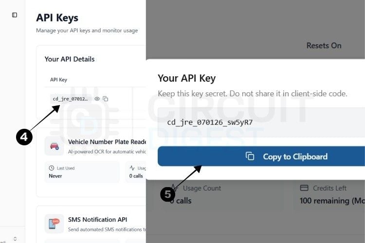
⇒ Step 5: By pressing the copy icon near the API Key, your key gets instantly copied to the clipboard.
Currently, there is a usage limit of 100 requests per API key for both the SMS and ANPR APIs and 10,000 data points for GPS tracking. Once you reach this limit, you can generate another key, which provides an additional 100 uses.
This usage limit is in place to prevent server overload.
With this, we are ready to move to hardware.
*Note: A 10-second rate limit applies to all API calls, allowing one request every 10 seconds.
Optional: Also, if you want to check out the full documentation and payload structure used by CircuitDigest Cloud and GeoLinker, you can refer to the comprehensive article: Free IoT-based GPS Tracking Map for ESP32, NodeMCU, and Arduino. This guide includes deeper technical insights and payload formatting examples.
Arduino IDE Setup for Raspberry Pi Pico GPS Tracker Projects
To get started with GeoLinker on the Raspberry Pi Pico / Pico W, follow these steps to install both the library and the board support package using the Arduino Library Manager and Boards Manager, no manual ZIP extraction required.
Step 1: Install RP2040 Board Support
Open Arduino IDE.
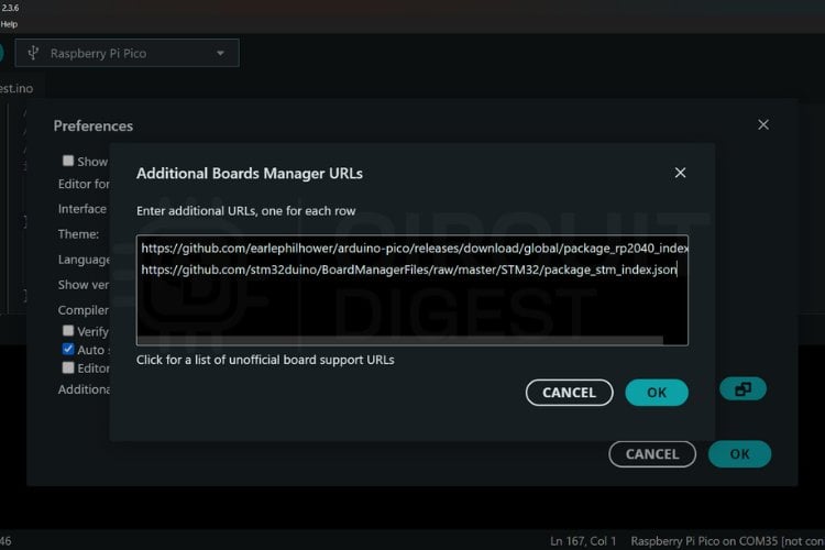
Go to File > Preferences.
In the "Additional Board Manager URLs" field, paste the following JSON
URL: https://github.com/earlephilhower/arduinopico/releases/download/global/package_rp2040_index.json
Click OK to close the Preferences window
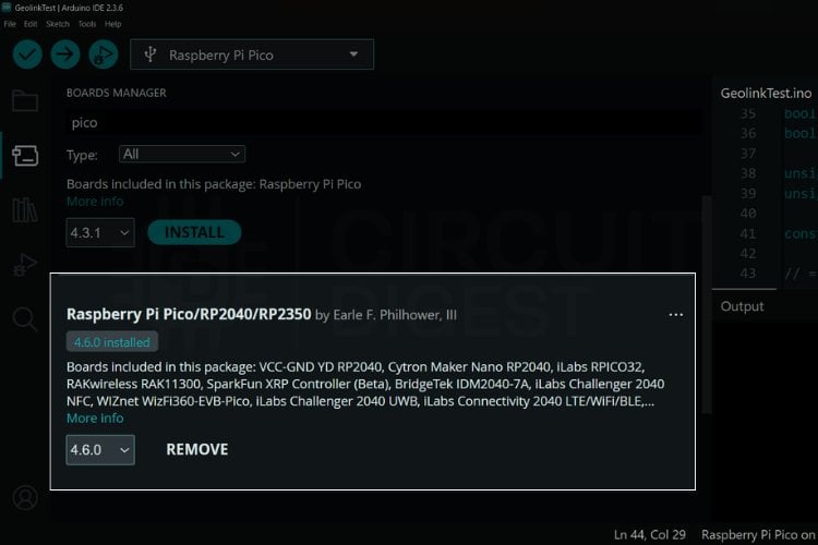
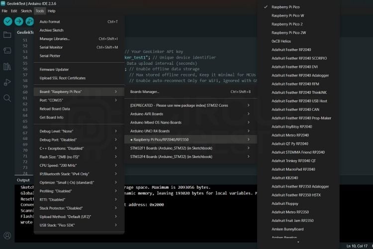
Go to Tools > Board > Boards Manager
Search for “RP2040” or “Raspberry Pi Pico”, then install “Raspberry Pi Pico / RP2040 by Earle Philhower”
Step 2: Install GeoLinker Library
Go to Tools > Manage Libraries...
In the Library Manager, search for: GeoLinker
Find GeoLinker by Jobit Joseph and click Install.
Once installed, you’ll find ready-to-use examples under: File > Examples > GeoLinker
This method ensures the latest version of the library and board support is always used, eliminates manual errors, and allows seamless updates through the IDE itself.
Troubleshooting Common GPS Tracker Issues
GeoLinker Library Not Appearing in Examples
If you don’t see the GeoLinker examples under File > Examples, try the following steps:
Restart Arduino IDE
After installing a new library via the Library Manager, it's a good idea to fully restart the Arduino
IDE to refresh its library index.
Check Folder Name, Ensure the folder is named exactly GeoLinker, and that it directly contains .h and .cpp files, not nested inside another subdirectory.
Confirm Successful Installation
Go to Tools > Manage Libraries…
Search for GeoLinker again
Ensure it shows as “Installed”, and the author is Jobit Joseph. If not installed, click the Install button.
Check Board Selection
Make sure you have a compatible board selected, like Raspberry Pi Pico or Pico W, under Tools > Board.
Some libraries, including GeoLinker, only show their examples when supported boards are selected.
Verify Board Platform is Installed
Make sure you’ve added the RP2040 board URL and installed the "Raspberry Pi Pico / RP2040 by Earle Philhower" package from Boards Manager.
Board Manager URL: https://github.com/earlephilhower/arduino-pico/releases/download/global/package_rp2040_index.json
Complete Arduino Code for Raspberry Pi Pico GPS Tracker
The following Arduino code demonstrates how to implement a fully functional Raspberry Pi Pico GPS tracker with real-time location monitoring capabilities and cellular IoT tracking features.
#include <GeoLinker.h>This line imports the GeoLinker library, which simplifies GPS and GSM-based IoT applications by internally handling GPS parsing, AT commands, modem initialisation, cloud communication, error tracking, and offline storage. It allows the user to interact with complex modules like Neo-6M and SIM800L using a high-level API.
GPS Serial Configuration
#define gpsSerial Serial2  // UART1
#define GPS_RX 4
#define GPS_TX 5
#define GPS_BAUD 9600   // Standard NMEA baud rate
This block sets up the UART communication for the GPS module. It assigns Serial2 (UART1 on Raspberry Pi Pico) for GPS communication and maps the RX and TX lines to GPIO pins 4 and 5, respectively. The baud rate is set to 9600, which is standard for most NMEA-output GPS modules such as Neo-6M. This configuration ensures that raw NMEA data can be read from the GPS module for parsing.
GSM SERIAL CONFIGURATION
#define gsmSerial Serial1  // UART0
#define GSM_RX 0
#define GSM_TX 1
#define GSM_BAUD 9600   // Standard modem baud rate
This section initialises the serial communication for the GSM modem. It uses Serial1 (UART0), with GPIO 0 as RX and GPIO 1 as TX, connected to the SIM800L module. The baud rate is again set to 9600 bps, which matches the default setting of most GSM modules. This setup enables two-way communication using AT commands to control the modem.
LED DEFINITIONS
#define LED_GREEN 21   // Success indicator
#define LED_YELLOW 20  // GPS error indicator
#define LED_RED 19     // GSM error indicator
Here, three LEDs are defined for status indication. The green LED (GPIO 21) signals a successful data upload. The yellow LED (GPIO 20) lights up when a GPS-related error occurs, such as no fix or parse failure. The red LED (GPIO 19) turns on when GSM-related problems arise, like SIM issues, network errors, or modem timeouts. These LEDs are used as real-time visual feedback tools.
Timing And State
bool greenLedOn = false;
unsigned long greenLedTimer = 0;
bool gpsErrorActive = false;
bool gsmErrorActive = false;
unsigned long lastGPSStatusTime = 0;
unsigned long lastGSMStatusTime = 0;
const unsigned long errorTimeout = 8000; // 8 seconds to auto-clear error
This section declares variables used to manage the status LEDs and track error timing. The greenLedOn flag keeps track of whether the green LED is currently active. Separate boolean flags (gpsErrorActive, gsmErrorActive) indicate whether a GPS or GSM error is ongoing. Timestamp variables track the last time errors occurred, and errorTimeout defines how long (8 seconds) an error should persist before auto-clearing.
Network Configuration
const char* apn = "gprs"; // Cellular APN
const char* gsmUser = nullptr;  // APN username if required
const char* gsmPass = nullptr;  // APN password if required
This part configures the network credentials for GSM connectivity. The APN (Access Point Name) is set to "gprs", which is commonly used by default on many GSM networks, but should be changed according to your SIM provider. The username and password fields are left null, which is appropriate for most consumer networks that don’t require authentication.
Geo Linker Configuration
const char* apiKey = "xxxxxxxx";  // Your GeoLinker API key
const char* deviceID = "GeoLinker_tracker_test1"; // Unique device identifier
const uint16_t updateInterval = 3;  // Data upload interval (seconds)
const bool enableOfflineStorage = true; // Enable offline data storage
const uint8_t offlineBufferLimit = 20;  // Max stored offline record, Keep it minimal for MCUs with less RAM
const bool enableAutoReconnect = true;  // Enable auto-reconnect Only for WiFi, Ignored with GSM
const int8_t timeOffsetHours = 5; // UTC + Hours
const int8_t timeOffsetMinutes = 30;  // UTC + Minutes
This configuration block sets up the GeoLinker tracking service. The apiKey is used to authenticate this device with the cloud backend. deviceID uniquely identifies the device. The updateInterval sets how frequently (in seconds) data should be sent. Offline storage is enabled to buffer unsent data if the network is temporarily unavailable, with a limit of 20 records. Auto-reconnect is enabled (mainly for WiFi, but harmless for GSM). Time offset is set to IST (UTC+5:30) for correct timestamp alignment.
GeoLinker Instance Creation
GeoLinker geo; //GeoLinker instanceThis line creates an instance of the GeoLinker class named geo. This object will be used throughout the program to manage payloads, GPS data, modem communication, and cloud interaction.
setup() Function
void setup() {
 Serial.begin(115200);
 delay(1000);
 // GPS UART
 gpsSerial.setTX(GPS_RX);
 gpsSerial.setRX(GPS_TX);
 gpsSerial.begin(GPS_BAUD);
 // GSM UART
 gsmSerial.setTX(GSM_RX);
 gsmSerial.setRX(GSM_TX);
 gsmSerial.begin(GSM_BAUD);
 // LED Setup
 pinMode(LED_GREEN, OUTPUT);
 pinMode(LED_YELLOW, OUTPUT);
 pinMode(LED_RED, OUTPUT);
 digitalWrite(LED_GREEN, LOW);
 digitalWrite(LED_YELLOW, LOW);
 digitalWrite(LED_RED, LOW);
 // GeoLinker Init
 geo.begin(Serial2);
 geo.setApiKey(apiKey);
 geo.setDeviceID(deviceID);
 geo.setUpdateInterval_seconds(updateInterval);
 geo.setDebugLevel(DEBUG_BASIC);
 geo.enableOfflineStorage(enableOfflineStorage);
 geo.setOfflineBufferLimit(offlineBufferLimit);
 geo.enableAutoReconnect(enableAutoReconnect);
 geo.setTimeOffset(timeOffsetHours, timeOffsetMinutes);
 geo.setNetworkMode(GEOLINKER_CELLULAR);
 geo.setModemCredentials(apn, gsmUser, gsmPass);
 geo.beginModem(Serial1);
 geo.setModemTimeouts(5000, 10000);
 Serial.println("GeoLinker setup complete.");
}
The setup() function is where hardware and library initialisation occur. It starts by initialising the USB serial console at 115200 bps. It then configures the GPS UART with the appropriate pins and baud rate, followed by setting up the GSM UART similarly. Each LED pin is set to output mode and turned off initially. Then, the GeoLinker instance is initialised using the GPS UART, followed by setting API credentials, upload interval, debug level, offline storage settings, and local time zone. The GSM modem is initialised using its serial port, and modem response timeouts are set. After successful initialisation, a message is printed to indicate completion.
Payload Preparation in loop()
unsigned long now = millis();
 // Example payload
 geo.setPayloads({
   {"temperature", 27.5},
   {"humidity", 65.3}
 });
 geo.setBatteryLevel(90);
Inside the loop() function, sensor data is simulated using hardcoded values. The setPayloads() method creates a key-value map that mimics sensor readings like temperature and humidity. The battery level is also manually set to 90%, which could be replaced by actual ADC readings in a real application.
Calling GeoLinker Main Loop
uint8_t status = geo.loop();This is the core line that drives the library's internal logic. The geo.loop() method processes the GPS data, prepares payloads, checks modem status, uploads data if possible, and returns a status code that indicates whether the data was sent successfully or if any error occurred. This is essential for managing the system state and triggering appropriate LED responses.
Handling Success with Green LED
if (status == STATUS_SENT) {
   Serial.println("Data sent successfully!");
   if (!greenLedOn) {
     digitalWrite(LED_GREEN, HIGH);
     delay(500);
     greenLedOn = true;
     greenLedTimer = now;
   }
   gpsErrorActive = false;
   gsmErrorActive = false;
 }
When the geo.loop() function returns STATUS_SENT, it means data was successfully transmitted to the cloud. A success message is printed to the console. The green LED is turned on briefly, and a timer is started to keep it on for one second. GPS and GSM error flags are also reset since a successful transmission implies normal operation.
Turning Off Green LED After Timeout
 if (greenLedOn && (now - greenLedTimer >= 1000)) {
   digitalWrite(LED_GREEN, LOW);
   greenLedOn = false;
 }
This checks if the green LED has been on for more than 1 second. If it has, the LED is turned off and the flag is cleared. This ensures the LED only briefly blinks on success, acting as a non-intrusive status indicator.
GPS Error Detection and Yellow LED Control
if (status == STATUS_GPS_ERROR || status == STATUS_PARSE_ERROR) {
   gpsErrorActive = true;
   lastGPSStatusTime = now;
 } else if (gpsErrorActive && (status == STATUS_SENT || status == 0)) {
   if (now - lastGPSStatusTime > errorTimeout) {
     gpsErrorActive = false;
   }
 }
 digitalWrite(LED_YELLOW, gpsErrorActive ? HIGH : LOW);
If the status indicates a GPS error (either no fix or a parsing problem), the gpsErrorActive flag is set and a timestamp is saved. If a later loop shows normal status (STATUS_SENT or 0), and 8 seconds have passed since the last error, the flag is cleared. Based on this flag, the yellow LED is either turned on or off to indicate the current GPS health.
GSM Error Detection and Red LED Control
bool gsmError = (
   status == STATUS_NETWORK_ERROR ||
   status == STATUS_CELLULAR_NOT_REGISTERED ||
   status == STATUS_CELLULAR_CTX_ERROR ||
   status == STATUS_CELLULAR_DATA_ERROR ||
   status == STATUS_CELLULAR_TIMEOUT ||
   status == STATUS_BAD_REQUEST_ERROR ||
   status == STATUS_INTERNAL_SERVER_ERROR
 );
 if (gsmError) {
   gsmErrorActive = true;
   lastGSMStatusTime = now;
 } else if (gsmErrorActive && (now - lastGSMStatusTime > errorTimeout)) {
   gsmErrorActive = false;
 }
 digitalWrite(LED_RED, gsmErrorActive ? HIGH : LOW);
This section evaluates whether the returned status represents a GSM-related error, including issues like modem timeout, SIM registration failure, context activation failure, or server response problems. If so, the gsmErrorActive flag is set. If these errors disappear and 8 seconds pass, the flag is cleared. The red LED reflects the flag state, giving a real-time indication of GSM problems.
How GeoLinker Works Internally
The GeoLinker library is designed to abstract the complexity involved in communicating with both the SIM800L GSM module and Neo-6M GPS receiver using UART serial ports. Internally, it uses a state-driven command handler to send, receive, parse, and validate data from both modules asynchronously.
SIM800L Communication - AT Command Flow
GeoLinker uses a sequence of AT commands to manage SIM initialisation, network registration, GPRS setup, and HTTP transactions. Here’s a typical command chain:
GeoLinker manages retries and checks responses for success (e.g., OK, +HTTPACTION: 1,200) before proceeding.
Neo-6M GPS Parsing Logic
The GPS module sends continuous NMEA sentences. GeoLinker listens on the GPS UART port and selectively extracts fields from:
$GPGGA: Extracts UTC time, fix quality, number of satellites, and altitude.
$GPRMC: Retrieves latitude, longitude, speed over ground, and date/time.
The library uses simple delimiters (comma-separated values) to tokenise NMEA strings and compute floating-point coordinates in decimal format.
State Machine and Watchdog
GeoLinker operates as a non-blocking state machine. Each geo.update() call evaluates current conditions (GSM ready, GPS fix, internet available) and advances the routine only when previous steps succeed. It includes built-in:
| Timeout handling | Delays and retry limits for slow network responses. |
| Fallback handling | Detects command errors and restarts failed sequences |
| Watchdog resets | Ensures system recovery in case of hangs or unresponsive modules. |
This architecture ensures robustness and simplicity in field deployments without deep user involvement in GSM protocol or GNSS parsing.
Users can override or expand library methods for custom HTTP headers, SMS alerts, or alternate GPS or GNSS formats (UBX, GSV, etc.).
Power Considerations
Use a 3.7V LiPo battery capable of >1.5A discharge.
Add a 470uF or higher capacitor near the SIM800L VCC-GND
Avoid using USB 5V directly if your module doesn't have a built-in regulator; instead, use a buck converter if needed.
Keep antenna wires away from power and data lines to reduce EMI.
Testing Raspberry Pi Pico GPS Tracker& Real-Time Tracking
After successfully uploading the code to the Raspberry Pi Pico, the GPS tracker system begins operating immediately. The Neo-6M module starts acquiring satellite signals to fetch real-time location data, while the SIM800L module handles communication with the cloud server via HTTP. As each GPS coordinate is collected, it's transmitted to the GeoLinker Cloud, where it's stored and visualised on the map in real time. During testing, we simulated internet connectivity loss to verify the offline data storage functionality of our cellular GPS tracker with Raspberry Pi Pico.
![]()
To test the system's reliability, especially under unstable network conditions, we simulated internet loss during our trial run. As expected, the device intelligently detected the connectivity issue and began storing the GPS data locally in a buffer. Once the connection was restored, the stored data points were automatically pushed to the server in the correct order, followed by new incoming data.
This test confirmed that the offline data handling feature works seamlessly, ensuring that no location information is lost, even when operating in areas with poor or intermittent GSM coverage. The live map view on the Circuit Digest Cloud has been updated accordingly, accurately reflecting the full movement path during the offline and online transition.
Troubleshooting
GPS Tracker Projects and Applications
GPS tracking offers more than just location logging; it powers real-world solutions in transportation, safety, asset monitoring, and more. We've explored several GPS-based projects that demonstrate how to collect, transmit, and visualise location data using affordable hardware like the Raspberry Pi Pico.
Practical Use Cases of Raspberry Pi Pico GPS Tracker
These examples highlight how GPS and GSM modules can be applied to real-world tracking systems:
Vehicle GPS Tracker with Cloud Logging: Sends continuous location updates to a remote server, ideal for fleet and vehicle monitoring.
SMS-based Location Responder: Share GPS coordinates via SMS when prompted. Great for emergency tracking without the internet.
Pet or Asset GPS Beacon: Periodically transmits location to a mobile app or dashboard. Useful for pets, bikes, or parcels.
Emergency Alert Button with Coordinates: Send a preset message and live location on button press. Perfect for SOS systems and elderly care.
Delivery & Fleet Tracking System: Logs real-time positions and timestamps for route tracking. Can integrate driver ID using RFID.
Whether you're building for personal use or large-scale deployments, these use cases offer practical blueprints to kickstart your GPS-powered IoT projects.
Working on this project using the Raspberry Pi Pico, the SIM800L GSM module, and the Neo-6M GPS receiver has been a rewarding journey. What made things smoother for me was the GeoLinker library; it took care of a lot of the headaches around GPS data parsing and GSM communication. Instead of wrestling with AT commands and NMEA strings, I could focus more on the actual logic of the system.
That said, I did run into a few challenges that might help others in the community. One big thing: HTTP POST requests over the SIM800L can be slow, especially if you're in an area with weak 2G coverage. I saw delays of several seconds at times, which could definitely be a deal-breaker for time-sensitive applications.
Another thing I learned the hard way is that power stability is crucial. The SIM800L is picky. If your power supply can't handle those quick current spikes during data transmission, the module might restart or freeze. I ended up adding extra capacitors and making sure my supply could handle peak loads, which helped a lot.
I'd love to hear how others in the community are expanding on setups like this, or if you’ve tackled similar challenges with power or network latency. Let’s share and improve together!
GitHub Repository with Arduino Code and Circuit


Previous GPS Tracker-Based Projects
From building real-time GPS loggers to integrating cloud mapping with GeoLinker, our past projects show how simple components can enable powerful location-based applications.
How to build a simple GPS Tracker using ESP32 and visualise data on a Map
We will build a GPS tracker using the ESP32 microcontroller and the Neo-6M GPS module as the main hardware components, with GeoLinker as the software component.
Free IoT-based GPS Tracking Map for ESP32, NodeMCU, and Arduino
Learn how to visualise GPS data with the CircuitDigest Cloud GeoLinker API. Capture coordinates, send them from embedded devices, and visualise routes with timestamps.
Build A Low Power SMS Based Vehicle Tracking System with an A9G GSM+GPS Module and Arduino
Here you will know about the A9G Module and how to make a Low Power SMS Based Vehicle Tracking System with A9G GSM+GPS Module and Arduino.
Complete Project Code
#include <GeoLinker.h>
// ==================================================================
//                   GPS SERIAL CONFIGURATION
// ==================================================================
#define gpsSerial Serial2  // UART1
#define GPS_RX 4
#define GPS_TX 5
#define GPS_BAUD 9600   // Standard NMEA baud rate
// ==================================================================
//                   GSM SERIAL CONFIGURATION
// ==================================================================
#define gsmSerial Serial1  // UART0
#define GSM_RX 0
#define GSM_TX 1
#define GSM_BAUD 9600   // Standard modem baud rate
// ==============================
//         LED DEFINITIONS
// ==============================
#define LED_GREEN 21   // Success indicator
#define LED_YELLOW 20  // GPS error indicator
#define LED_RED 19     // GSM error indicator
// ==============================
//       TIMING AND STATE
// ==============================
bool greenLedOn = false;
unsigned long greenLedTimer = 0;
bool gpsErrorActive = false;
bool gsmErrorActive = false;
unsigned long lastGPSStatusTime = 0;
unsigned long lastGSMStatusTime = 0;
const unsigned long errorTimeout = 8000; // 8 seconds to auto-clear error
// ==============================
//     NETWORK CONFIGURATION
// ==============================
const char* apn = "gprs"; // Cellular APN
const char* gsmUser = nullptr;  // APN username if required
const char* gsmPass = nullptr;  // APN password if required

// ==============================
//    GEO LINKER CONFIGURATION
// ==============================
const char* apiKey = "xxxxxxx";  // Your GeoLinker API key
const char* deviceID = "GeoLinker_tracker_test1"; // Unique device identifier
const uint16_t updateInterval = 3;  // Data upload interval (seconds)
const bool enableOfflineStorage = true; // Enable offline data storage
const uint8_t offlineBufferLimit = 20;  // Max stored offline record, Keep it minimal for MCUs with less RAM
const bool enableAutoReconnect = true;  // Enable auto-reconnect Only for WiFi, Ignored with GSM
const int8_t timeOffsetHours = 5; // UTC + Hours
const int8_t timeOffsetMinutes = 30;  // UTC + Minutes

GeoLinker geo;  //GeoLinker instance

void setup() {
 Serial.begin(115200);
 delay(1000);

 // GPS UART
 gpsSerial.setTX(GPS_RX);
 gpsSerial.setRX(GPS_TX);
 gpsSerial.begin(GPS_BAUD);

 // GSM UART
 gsmSerial.setTX(GSM_RX);
 gsmSerial.setRX(GSM_TX);
 gsmSerial.begin(GSM_BAUD);

 // LED Setup
 pinMode(LED_GREEN, OUTPUT);
 pinMode(LED_YELLOW, OUTPUT);
 pinMode(LED_RED, OUTPUT);
 digitalWrite(LED_GREEN, LOW);
 digitalWrite(LED_YELLOW, LOW);
 digitalWrite(LED_RED, LOW);

 // GeoLinker Init
 geo.begin(Serial2);
 geo.setApiKey(apiKey);
 geo.setDeviceID(deviceID);
 geo.setUpdateInterval_seconds(updateInterval);
 geo.setDebugLevel(DEBUG_BASIC);
 geo.enableOfflineStorage(enableOfflineStorage);
 geo.setOfflineBufferLimit(offlineBufferLimit);
 geo.enableAutoReconnect(enableAutoReconnect);
 geo.setTimeOffset(timeOffsetHours, timeOffsetMinutes);

 geo.setNetworkMode(GEOLINKER_CELLULAR);
 geo.setModemCredentials(apn, gsmUser, gsmPass);
 geo.beginModem(Serial1);
 geo.setModemTimeouts(5000, 10000);

 Serial.println("GeoLinker setup complete.");
}

void loop() {
 unsigned long now = millis();

 // Example payload
 geo.setPayloads({
   {"temperature", 27.5},
   {"humidity", 65.3}
 });

 geo.setBatteryLevel(90);

 uint8_t status = geo.loop();

 // =========================================
 //  SUCCESS: Green LED for 1 second
 // =========================================
 if (status == STATUS_SENT) {
   Serial.println("Data sent successfully!");

   if (!greenLedOn) {
     digitalWrite(LED_GREEN, HIGH);
     delay(500);
     greenLedOn = true;
     greenLedTimer = now;
   }

   gpsErrorActive = false;
   gsmErrorActive = false;
 }

 if (greenLedOn && (now - greenLedTimer >= 1000)) {
   digitalWrite(LED_GREEN, LOW);
   greenLedOn = false;
 }


 // =========================================
 //  GPS ERROR LED Handling
 // =========================================
 if (status == STATUS_GPS_ERROR || status == STATUS_PARSE_ERROR) {
   gpsErrorActive = true;
   lastGPSStatusTime = now;
 } else if (gpsErrorActive && (status == STATUS_SENT || status == 0)) {
   if (now - lastGPSStatusTime > errorTimeout) {
     gpsErrorActive = false;
   }
 }

 digitalWrite(LED_YELLOW, gpsErrorActive ? HIGH : LOW);

 // =========================================
 //  GSM ERROR LED Handling
 // =========================================
 bool gsmError = (
   status == STATUS_NETWORK_ERROR ||
   status == STATUS_CELLULAR_NOT_REGISTERED ||
   status == STATUS_CELLULAR_CTX_ERROR ||
   status == STATUS_CELLULAR_DATA_ERROR ||
   status == STATUS_CELLULAR_TIMEOUT ||
   status == STATUS_BAD_REQUEST_ERROR ||
   status == STATUS_INTERNAL_SERVER_ERROR
 );

 if (gsmError) {
   gsmErrorActive = true;
   lastGSMStatusTime = now;
 } else if (gsmErrorActive && (now - lastGSMStatusTime > errorTimeout)) {
   gsmErrorActive = false;
 }

 digitalWrite(LED_RED, gsmErrorActive ? HIGH : LOW);
}
Comments
This dumb guy use software serial...

This is boolshit!
/tmp/.arduinoIDE-unsaved2025923-45371-m5bxds.g328/sketch_oct23a/sketch_oct23a.ino: In function 'void setup()':
/tmp/.arduinoIDE-unsaved2025923-45371-m5bxds.g328/sketch_oct23a/sketch_oct23a.ino:54:12: error: 'class HardwareSerial' has no member named 'setTX'
54 | gpsSerial.setTX(GPS_RX);
| ^~~~~
/tmp/.arduinoIDE-unsaved2025923-45371-m5bxds.g328/sketch_oct23a/sketch_oct23a.ino:55:12: error: 'class HardwareSerial' has no member named 'setRX'
55 | gpsSerial.setRX(GPS_TX);
| ^~~~~
/tmp/.arduinoIDE-unsaved2025923-45371-m5bxds.g328/sketch_oct23a/sketch_oct23a.ino:58:12: error: 'class HardwareSerial' has no member named 'setTX'
58 | gsmSerial.setTX(GSM_RX);
| ^~~~~
/tmp/.arduinoIDE-unsaved2025923-45371-m5bxds.g328/sketch_oct23a/sketch_oct23a.ino:59:12: error: 'class HardwareSerial' has no member named 'setRX'
59 | gsmSerial.setRX(GSM_TX);
| ^~~~~