
Microcontrollers work only with digital values but in real world we have to deal with Analog signals. That’s why ADC (Analog to Digital Converters) is there to convert real world Analog values into Digital form so that microcontrollers can process the signals. But what if we need Analog signals from digital values, so here comes the DAC (Digital to Analog Converter).
DAC can be used in many applications such as Motor control, Control Brightness of the LED Lights, Audio Amplifier, Video Encoders, Data Acquisition Systems etc.
We already interfaced MCP4725 DAC Module with Arduino and STM32. Today we will use the same MCP4725 DAC IC to design a Digital to Analog converter using Raspberry Pi. It is assumed that you have already installed the latest OS on your Raspberry PI and have access to it via SSH. If not, follow the Getting started with Raspberry Pi tutorial before proceeding. Here we are using Rasbian Stretch installed on Raspberry Pi 3.
Components Required
- Raspberry Pi 3 B+ (With Raspbian OS installed)
- MCP4725 DAC IC
- 16x2 LCD display
- Breadboard
- Connecting Wires
MCP4725 DAC Module (Digital to Analog Converter)
MCP4725 IC is a 12-Bit Digital to Analog Converter Module which is used to generate output analog voltages from (0 to 5V) and it is controlled by using I2C communication. It also comes with on board nonvolatile memory EEPROM.
This IC has 12-Bit resolution. This means we use (0 to 4096) as input to provide the voltage output with respect to reference voltage. Maximum reference voltage is 5V.
Formula to calculate Output Voltage
O/P Voltage = (Reference Voltage / Resolution) x Digital Value
For Example if we use 5V as reference voltage and let’s assume that digital value is 2048. So to calculate the DAC output.
O/P Voltage = (5/ 4096) x 2048 = 2.5V
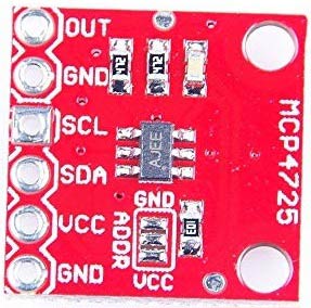
Pinout of MCP4725
Below is the image of MCP4725 with clearly indicating pin names.
|
Pins of MCP4725 |
Use |
|
OUT |
Outputs Analog Voltage |
|
GND |
GND for Output |
|
SCL |
I2C Serial Clock line |
|
SDA |
I2C Serial Data line |
|
VCC |
Input Reference Voltage 5V or 3.3V |
|
GND |
GND for input |
This IC can be controlled using the I2C communication which requires only two wires SCL and SDA. By default, the I2C address for MCP4725 is 0x60. Now we know about I2C communication in Raspberry pi.
I2C pins in Raspberry Pi
In order to use MCP4725 with Raspberry Pi, the first thing to do is knowing the Raspberry Pi I2C port pins and configuring I2C port in the Raspberry pi.
Below is the Pin Diagram of Raspberry Pi 3 Model B+, and I2C pins GPIO2 (SDA) and GPIO3 (SCL) are used in this tutorial.
Configuring I2C in Raspberry Pi
By default, I2C is disabled in Raspberry Pi. So first it must be enabled. To enable the I2C in Raspberry Pi
1. Go to the terminal and type sudo raspi-config.
2. Now the Raspberry Pi Software Configuration Tool appears.
3. Select Interfacing options and then enable the I2C.
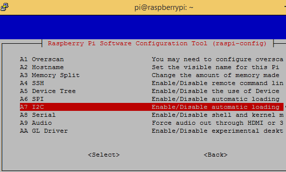
4. After enabling the I2C reboot the Pi.
Scanning I2C Address of MCP4725 using Raspberry Pi
Now in order to start communication with the MCP4725 IC, the Raspberry Pi must know its I2C address. To find the address first connect the SDA and SCL pin of MCP4725 to the SDA and SCL pin of Raspberry Pi. Also connect the +5V and GND pins.
Now open the terminal and type below command to know the address of connected I2C device,
sudo i2cdetect –y 1 or sudo i2cdetect –y 0
After finding the I2C address now its time to install the necessary libraries for using MCP4725 with Raspberry Pi.
Installing MCP4725 Adafruit library into Raspberry Pi
In order to use MCP4725 DAC board with I2C bus of Raspberry Pi, a Adafruit MCP4725 library is used. To download and install the library follow these steps:
1. Make sure Raspberry Pi is connected to an active internet.
2. Next open a terminal and run the following lines one by one.
sudo apt-get install git build-essential python-dev
git clone https://github.com/adafruit/Adafruit_Python_MCP4725.git
cd Adafruit_Python_MCP4725
sudo python setup.py install
3. After successful installation now the Adafruit MCP4725 library can be imported in any python script by using the line
Import Adafruit_MCP4725
Installing Adafruit LCD display library
A LCD is used in this project to display the DAC and analog voltage values so to download and install the LCD library in Raspberry Pi follow these steps:
1. Open a terminal window and run the following lines one by one.
apt-get install git
git clone https://github.com/adafruit/Adafruit_Python_CharLCD.git
cd Adafruit_Python_CharLCD
sudo python setup.py install
2. After installation of LCD library now the Adafruit_python_CharLCD can be used from any python script by using the following line
import Adafruit_CharLCD as LCD
Now the Raspberry Pi is ready to code for Digital to Analog converter so let’s connect the circuit as shown in the figure below.
Circuit Diagram and Connections
Circuit diagram for using DAC IC MCP4725 with Raspberry Pi is given below:

Circuit Connections between (16x2) LCD & Raspberry Pi
|
LCD |
Raspberry Pi 3 B+ |
|
VSS |
GND |
|
VDD |
+5V |
|
V0 |
From potentiometer for contrast control |
|
RS |
GPIO25 |
|
RW |
GND |
|
E |
GPIO24 |
|
D4 |
GPIO23 |
|
D5 |
GPIO17 |
|
D6 |
GPIO18 |
|
D7 |
GPIO22 |
|
A |
+5V |
|
K |
GND |
Circuit Connections between MCP4725 & Raspberry Pi
|
MCP4725 |
Raspberry Pi 3 B+ |
Multimeter |
|
GND |
GND |
Negative Probe |
|
VCC |
+5V |
- |
|
SDA |
GPIO2 (SDA) |
- |
|
SCL |
GPIO3 (SCL) |
- |
|
OUT |
- |
Positive Probe |
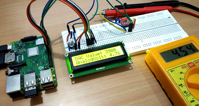
Complete setup will look like this:
Programming Raspberry Pi for Digital to Analog Conversion
Complete Python code for Raspberry Pi is given at the end of this tutorial. Just upload it into raspberry pi using any SSH client like Putty or any FTP client like FileZilla or you can directly write program into raspberry pi by connecting a monitor to it. Learn more about programming raspberry Pi here.
In this program a digital value of 0-4096 is sent from Raspberry Pi to the MCP4725 via I2C bus to produce an analog output voltage of 0 to 5V which can be verified with the multimeter. Both the digital and analog values are displayed on the 16x2 LCD. In our program the digital value is sent with an increment of 150 using for loop (0,150,300,450…4050). Let’s see the program in detail.
First include all the required libraries. Here LCD, MCP4725 and time library are used.
import Adafruit_CharLCD as LCD
import Adafruit_MCP4725
import time
Next define the LCD pins along with the no. of row and columns. We know that 16X2 LCD has 2 rows and 16 columns. Learn more about interfacing LCD with Raspberry Pi here.
lcd_rs        = 25
lcd_en        = 24
lcd_d4        = 23
lcd_d5        = 17
lcd_d6        = 18
lcd_d7        = 22
lcd_backlight = 4

# Define LCD column and row size for 16x2 LCD.
lcd_columns = 16
lcd_rows    = 2
lcd = LCD.Adafruit_CharLCD(lcd_rs, lcd_en, lcd_d4, lcd_d5, lcd_d6, lcd_d7,lcd_columns, lcd_rows, lcd_backlight)
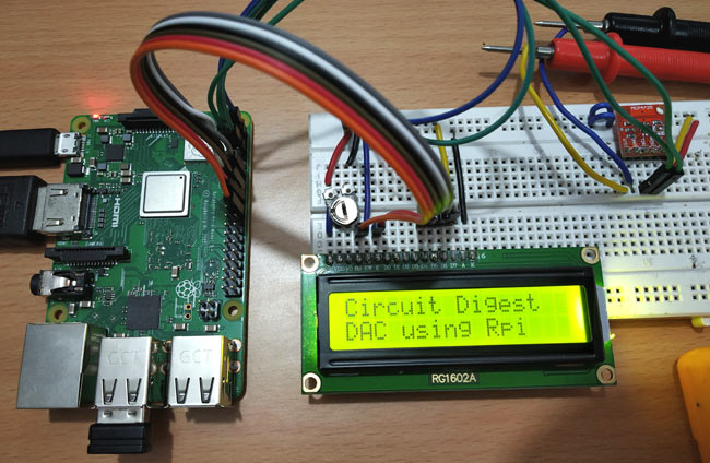
Next display some welcome message on LCD for five seconds.
lcd.message('Circuit Digest')
time.sleep(2.0)
lcd.message('\nDAC using Rpi')
time.sleep(5.0)
lcd.clear()
In the next line, a DAC instance is created with the I2C address of the MCP4725 DAC IC. My board has an address of 0x60, change it according to your board.
dac = Adafruit_MCP4725.MCP4725(address=0x60)
Next a for loop is used inside while loop to change the digital value x that is sent to MCP4725 via I2C bus. The for loop range is (0,4095,150). The x values vary from 0 to 4050 with an increment of 150.
while True:
    for x in range(0,4097,150):
The Digital value is sent to MCP4725 using the following line
dac.set_voltage(x)
Depending upon the digital value the analog value is calculated using the formula where 5 is reference voltage and x is digital value.
voltage = x/4096.0*5.0
Then the Digital value & Analog value are displayed on the LCD with a delay of 2 seconds using the following lines
           lcd.cursor_pos = (0,0)
           lcd.message("DAC Value: " + str(x))
           lcd.message("\nAnalogVolt: %.2f" % voltage)
           time.sleep(2)
Here the Digital value is shown in the first row and analog value in second row of LCD display. A multimeter is also connected to the MCP4725 Output Pins to verify the analog voltage.
Complete code with demonstration Video is given below.
Complete Project Code
import Adafruit_CharLCD as LCD

import Adafruit_MCP4725

import time
lcd_rs        = 25

lcd_en        = 24

lcd_d4        = 23

lcd_d5        = 17

lcd_d6        = 18

lcd_d7        = 22

lcd_backlight = 4
# Define LCD column and row size for 16x2 LCD.

lcd_columns = 16

lcd_rows    = 2
lcd = LCD.Adafruit_CharLCD(lcd_rs, lcd_en, lcd_d4, lcd_d5, lcd_d6, lcd_d7,

                           lcd_columns, lcd_rows, lcd_backlight)
lcd.message('Circuit Digest')

time.sleep(2.0)

lcd.message('\nDAC using Rpi')

time.sleep(5.0)

lcd.clear()

dac = Adafruit_MCP4725.MCP4725(address=0x60)
while True:

    for x in range(0,4097,150):


        print(x)

        dac.set_voltage(x)

        lcd.cursor_pos = (0,0)

        lcd.message("DAC Value: " + str(x))

        voltage = x/4096.0*5.0

        lcd.message("\nAnalogVolt: %.2f" % voltage)

        time.sleep(2)

        lcd.clear()
