
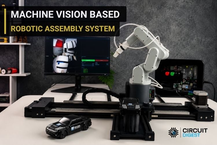
Industrial automation has revolutionized manufacturing by making production faster, more accurate, and highly consistent. Modern robotic assembly systems combine robotic arms, machine vision, motion control, and embedded control electronics to automate repetitive tasks with minimal human intervention. While these systems are widely used in industries, the same concepts can also be demonstrated using compact and affordable hardware.
In this project, we built a machine vision-based robotic assembly system that automatically assembles a miniature 3D-printed toy car from individual components. The system uses a MechArm 270 M5 mounted on a motorized linear rail to access multiple workstations, while an NVIDIA Jetson Nano running OpenCV verifies each component before it is picked. A custom ESP32-based controller board manages the linear rail, sensors, and control panel peripherals, while a custom web dashboard provides real-time monitoring and control. Together, these technologies demonstrate how robotics, computer vision, and embedded systems can be integrated into a compact industrial-style automated assembly cell.
If you enjoy robotics and automation, don't miss our Robotics Projects section. It features a wide range of DIY robotic arms, autonomous robots, machine vision systems, and embedded electronics projects with detailed build guides.
Table of Contents
System Overview
The system architecture provides a high-level overview of how the different hardware components are connected and interact with one another. It illustrates the communication between the Jetson Nano, MechArm 270, custom ESP32 controller board, machine vision system, and the linear rail, showing how they work together to perform the automated assembly process.
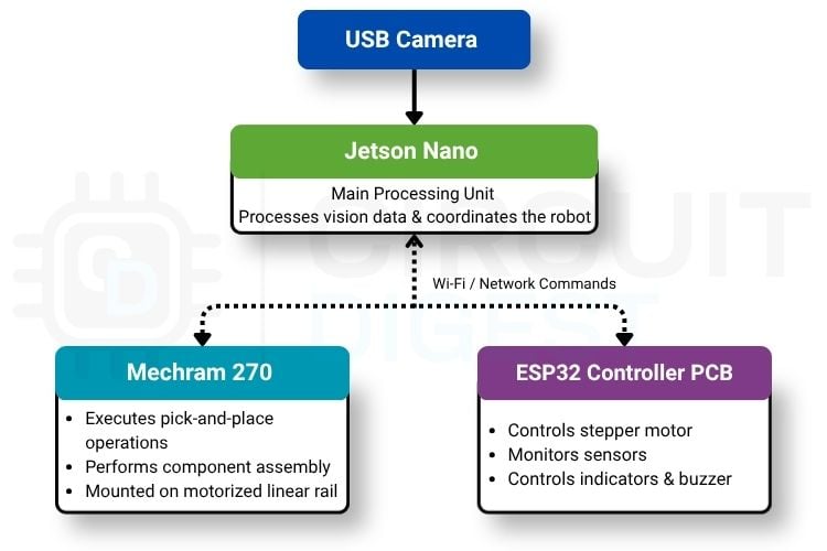
The system architecture is centered around the NVIDIA Jetson Nano, which acts as the main processing unit and coordinates the entire assembly process. A USB camera mounted near the robotic arm continuously captures images of the component trays and sends them to the Jetson Nano, where OpenCV-based machine vision algorithms inspect the required pickup location, verify the presence of the component, and confirm its color before each pick operation.
Assembly Workflow
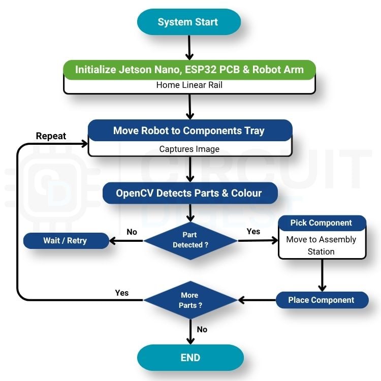
The robotic assembly system follows a predefined workflow to ensure that each component is picked, verified, and assembled in the correct order. Instead of blindly picking components, the system uses computer vision to inspect every pickup location before the robotic arm performs the pick-and-place operation. This verification step helps improve the reliability of the assembly process by ensuring that the correct part is available before proceeding. The complete workflow of the system is illustrated in the flowchart below.
Step 1⇒ System Initialization
When the system is powered on, the Jetson Nano, ESP32 control PCB, and MechArm 270 are initialized. The linear rail then performs a homing sequence using the limit switch to establish its reference position.
Step 2⇒ Move to the Component Tray
The ESP32 control PCB moves the robotic arm along the linear rail to the required component tray based on the predefined assembly sequence.
Step 3⇒ Component Inspection
A USB camera mounted near the end effector captures an image of the component tray. The Jetson Nano processes the image using OpenCV to verify the presence and color of the required component.
Step 4⇒ Pick the Component
After successful verification, the robotic arm picks up the component from the tray. If the required part is not detected, the system waits or retries the inspection.
Step 5⇒ Assemble the Component
The robotic arm places the component at the assembly station in its designated position. The process is repeated until all the required components have been assembled.
Step 6⇒ Assembly Complete
Once the final component is assembled, the robotic arm returns to its home position, and the system waits for the next assembly cycle.
Components Required
The robotic assembly system is built using a combination of commercially available electronic components, industrial mechanical hardware, and custom-designed parts.
Most of the electronic components were sourced from Mouser Electronics, while the mechanical structure was built using aluminium profiles, linear guides, and other standard automation components. To meet the project's specific requirements, several parts like mounting brackets, component trays, and mechanical fixtures were designed and 3D printed. The complete list of components used in this project is provided in the table below.
| S.no | Component Name | Part Number | Qty |
| 1. | NVIDIA Jetson Orin NX | 713-110110144 | 1 |
| 2. | Power Supplies - 12DC/120W | 651-1585283 | 1 |
| 3. | Power Supplies -12DC/75W | 651-1585280 | 1 |
| 4. | Circuit Breakers | 655-2486200-1 | 1 |
| 5. | Contactors - Electromechanical CBL-SC-230UC/20/32A | 651-1791341 | 1 |
| 6. | Emergency Stop Switch | 655-PBES16N50R | 1 |
| 7. | LED Indicator, GREEN & RED 24V-240VAC/DC | 655-2-2489541-0 | 2 |
| 8. | Hall Effect / Magnetic Sensors | 576-54140-17X-02-A | 1 |
| 9. | Resettable Fuses - PPTC 30V | 576-30R300UPR | 1 |
| 10. | ESD Protection Diodes / TVS Diodes | 576-SP0504BAHTG | 1 |
| 11. | Industrial BUZZER 12VAC/DC | 655-2489542-1 | 1 |
| 12. | Fixed Terminal Blocks | 571-282869-2 | 4 |
| 13. | ESP32-S3 Module | 356-ESP32S3WRM1N16R8 | 1 |
| 14. | Headers & Wire Housings 2.5MM 3pos | 571-440053-3 | 5 |
| 15. | Headers & Wire Housings 2.5mm 4pos | 571-440053-4 | 1 |
| 16. | Headers & Wire Housings 2.5mm 2pos | 571-440053-2 | 1 |
| 17. | Electrolytic Capacitors - SMD 220UF 35V | 594-MAL215097001E3 | 2 |
| 18. | Inductor - 470uh SMD | 704-DR1040-470-H | 1 |
| 19. | Circuit Breakers 120/240V 10A | 576-HCBY1P10GA850 | 1 |
| 20. | NTC Thermistor 1K OHM | 576-USUR1000-102G-06 | 1 |
| 21. | Stepper Motor | 700-QSH5718-76-28189 | 1 |
| 22. | Stepper Motor Driver | 700-TMC5160-BOB | 1 |
| 23. | IMX335 5MP USB Camera | ---- | 1 |
| 24. | Limit Switch | ---- | 1 |
| 25. | Drag chain | ---- | As required |
| 26. | Aluminum Profiles | ---- | As required |
To improve the system's reliability, the electronic components were sourced from well-established industrial manufacturers. The project incorporates products from Littelfuse, Phoenix Contact, TE Connectivity, and Analog Devices covering areas such as circuit protection, power distribution, industrial connectivity, and embedded electronics.
Robotic Arm - MechArm 270
The heart of this project is the MechArm 270 from Elephant Robotics, specifically the M5Stack version. We selected this robotic arm because it offers a compact desktop form factor while still providing the flexibility of a six-axis industrial-style manipulator. Despite its small footprint, it can perform precise pick-and-place operations, making it an excellent choice for prototyping compact automation systems. Another advantage of the MechArm 270 is its beginner-friendly ecosystem, with support for Python programming, ROS, and multiple communication interfaces, allowing it to be easily integrated into custom automation projects.
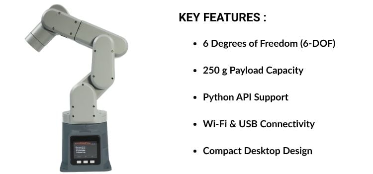
The MechArm 270 can be controlled through both USB and Wi-Fi, making it flexible for different application requirements. In this project, the robotic arm communicates wirelessly with the NVIDIA Jetson Nano using the Python API provided by Elephant Robotics. This allows the Jetson Nano to send movement commands after completing the machine vision inspection, creating a seamless workflow between vision processing and robotic manipulation.
To handle the lightweight 3D-printed car components, the standard end effector was replaced with a vacuum gripper. Unlike conventional mechanical grippers, the vacuum gripper securely lifts small plastic components by creating suction, making it ideal for parts that are lightweight, flat, or difficult to grasp mechanically. This results in more reliable pick-and-place operations while reducing the risk of damaging the components.
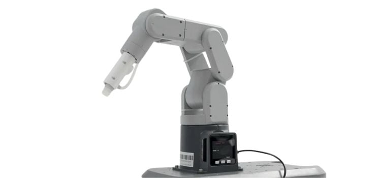
The vacuum gripper is powered directly from the robotic arm, with both the power supply and control signals routed through the arm's built-in GPIO interface. This eliminates the need for additional external wiring and allows the gripper to be controlled directly from the robot program. During the assembly sequence, the robotic arm activates the vacuum gripper to pick up a component, transports it to the assembly station, and then releases the suction once the part has been accurately positioned.
Don't have a commercial robotic arm? No problem! We've published several DIY robotic arm projects that you can build yourself using readily available components. If you're looking for more options, our "Top 10 Open-Source Robotic Arms For Beginners" guide compares some of the best open-source robotic arms for learning, research, and automation.
Linear Rail
While the MechArm 270 provides sufficient reach for desktop automation, its workspace is limited to a 270 mm operating radius. To enable the robotic arm to access multiple component trays and the assembly station, it is mounted on a custom-built motorized linear rail, effectively adding an axis of motion. This extended workspace allows the robot to travel between different pickup locations without repositioning the workpieces, making the overall assembly process more efficient and flexible.
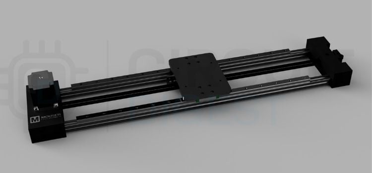
The linear motion platform is built using an aluminium profile frame, a precision linear guide rail, and a stepper motor to provide smooth and accurate movement along the X-axis. Several custom 3D-printed parts were designed to mount the robotic arm, support the moving carriage, and integrate the drive mechanism, allowing the platform to be customised for the project's mechanical requirements while maintaining a rigid and stable structure.
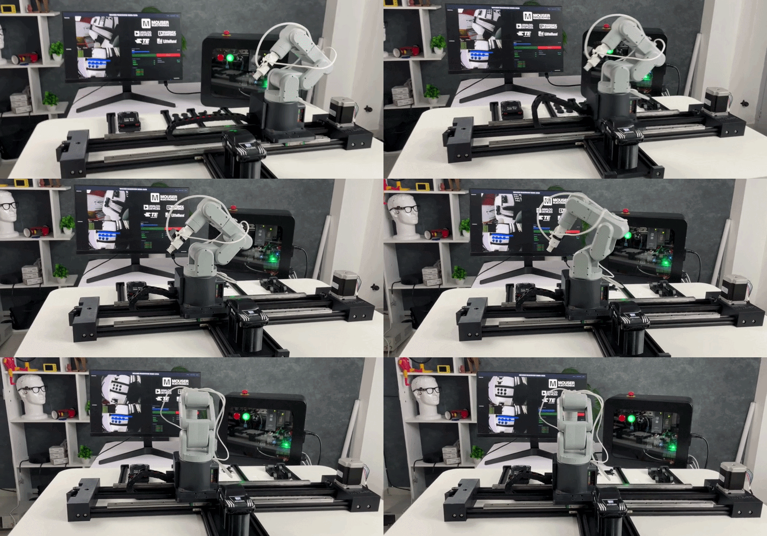
To ensure repeatable positioning, a limit switch is installed at one end of the rail and used as the homing sensor. During system startup, the carriage moves to this reference position, establishing a known origin before the assembly cycle begins. A cable drag chain is also incorporated into the design to safely route the power, communication, and vacuum tubing connected to the robotic arm. This prevents cable entanglement, minimises mechanical stress during continuous motion, and gives the system a cleaner, more organised appearance similar to that of industrial automation equipment.
Control Panel
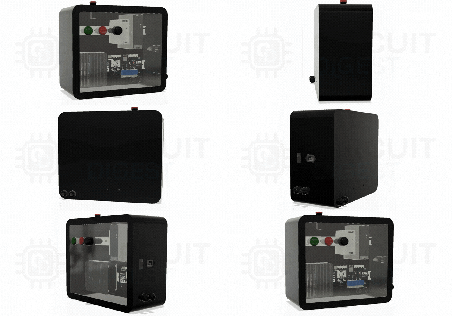
The control panel serves as the central hub of the robotic assembly system, housing all the electronics required for motion control, vision processing, power distribution, and system monitoring. Instead of distributing the electronics across the machine, the control panel provides a centralised and organized enclosure that simplifies wiring, improves maintenance, and protects the electronic components during operation.
Control Panel Architecture
The control panel serves as the central power distribution and control unit for the robotic assembly system. A 240V AC mains input first passes through a Littelfuse Miniature Circuit Breaker (MCB), protecting against overloads and short circuits. The power is then divided into two separate branches. The controller section is powered by a 12V, 120W DIN-rail power supply from Phoenix Contact, which supplies the NVIDIA Jetson Nano, the custom ESP32 controller board, and all the onboard peripherals. The robotic arm is powered independently using a 12V, 75W Phoenix Contact power supply, ensuring that the control electronics remain operational even if the robot's power is interrupted.
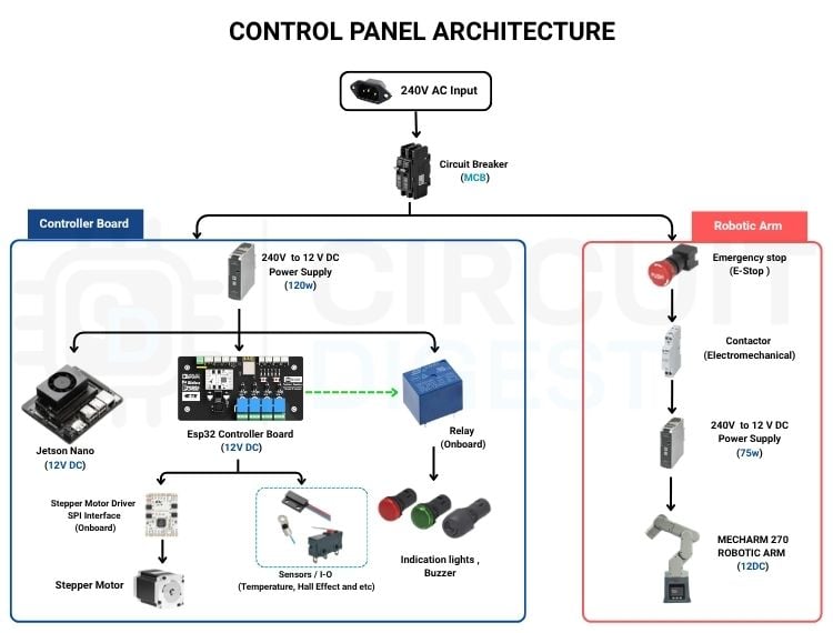
For safety, the robotic arm power line passes through an Emergency Stop switch and a Phoenix Contact electromechanical contactor, allowing the arm to be disconnected instantly while keeping the controller section active. The custom ESP32 controller board interfaces with the TMC5160 stepper motor driver, stepper motor, Hall-effect and temperature sensors, status indicators, relay, and industrial buzzer to manage the linear rail and monitor the overall system. Reliable connectivity is achieved using TE Connectivity connectors and terminal blocks, while Littelfuse protection devices safeguard the controller against overcurrent and ESD events. Most of the electronic components used in the control panel were sourced through Mouser Electronics, with industrial-grade products from Phoenix Contact, Littelfuse, TE Connectivity, and Analog Devices contributing to the system's reliability and robustness.
Custom PCB
We designed a dedicated ESP32-based Controller Board that brings all the essential control functions onto a single PCB. It handles the linear rail motion, sensor inputs, relay outputs, and other peripheral connections, eliminating the need for multiple development boards and scattered wiring inside the control panel. This not only makes the system easier to assemble and troubleshoot but also gives it a cleaner, more reliable design. To further improve the installation, the controller board is mounted on a DIN rail inside the control panel, making it easy to install, replace, and maintain while following standard industrial panel practices.

The figure above shows the complete schematic of the ESP32 Controller Board, illustrating the various circuits integrated into the design, including power regulation, motor control, sensor interfaces, and relay outputs. After completing the schematic, the PCB was designed and fabricated as shown below, resulting in a compact controller board that neatly integrates all the required hardware for the robotic assembly system.
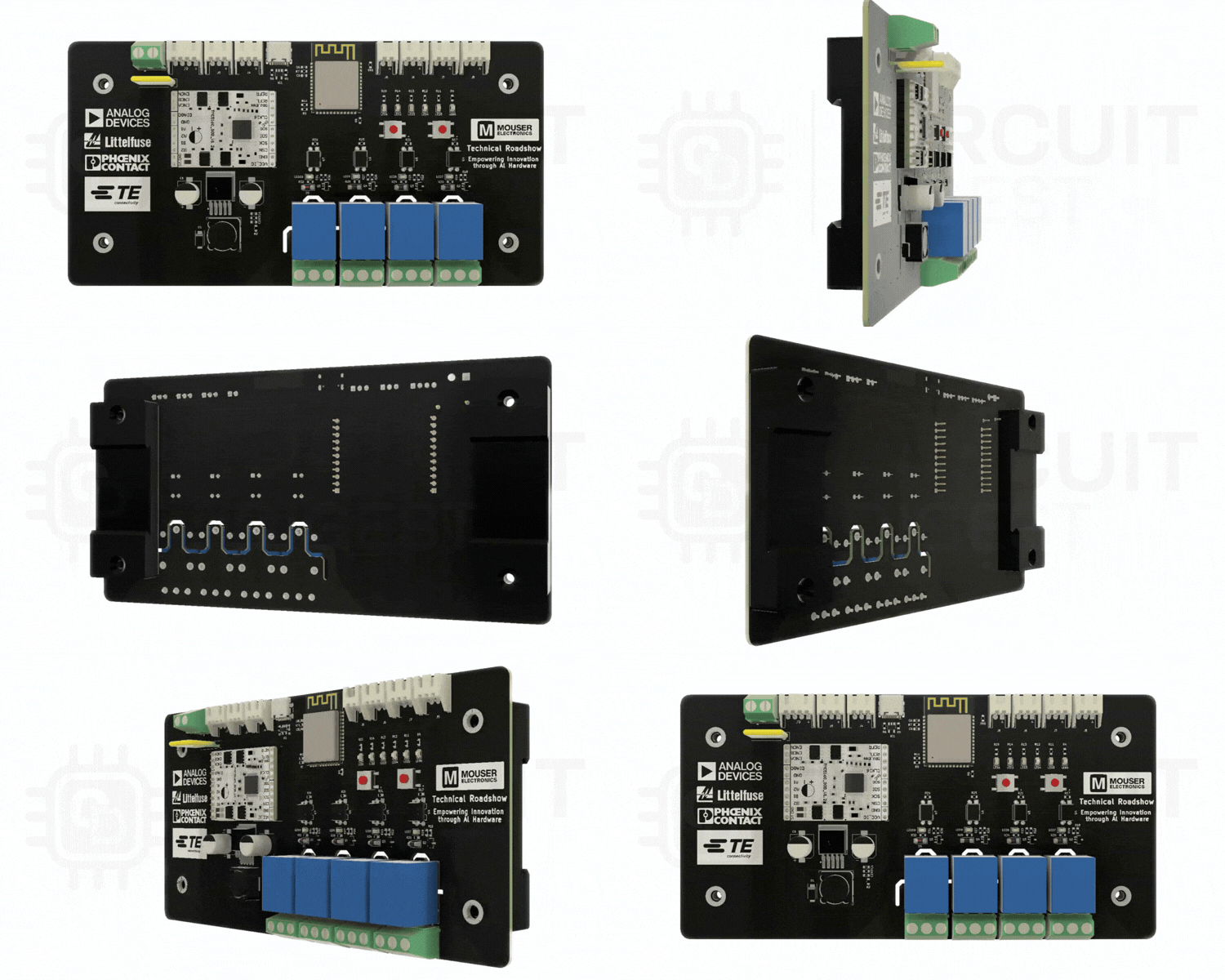
With the controller board assembled and integrated into the control panel, it serves as the central interface between the hardware components and the overall automation system. By handling motion control, sensor monitoring, and peripheral interfaces on a single PCB, the design simplifies system integration while providing a reliable foundation for the robotic assembly cell. The next section focuses on the NVIDIA Jetson Nano, which performs the machine vision processing and coordinates the overall assembly workflow.
Jetson Nano
To enable machine vision, the system requires a computing platform capable of processing images captured by the camera mounted on the robotic arm. For this project, we selected the Seeed Studio reComputer J401, based on the NVIDIA Jetson Nano. While a Raspberry Pi would have been sufficient for basic OpenCV-based image processing, the Jetson Nano offers significantly higher GPU computing capability, making it a better choice for future expansion. This provides the flexibility to integrate edge AI features such as object classification, defect detection, or intelligent inspection without requiring major hardware changes. Its compact form factor also allows it to be easily installed inside the control panel alongside the controller board.
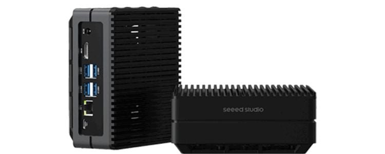
The panel contains a Controller Board ( Customs PCB design ) responsible for controlling the linear motion system and interfacing with various sensors and peripherals. It also houses the NVIDIA Jetson Nano, which performs all computer vision and high-level processing tasks. In addition, the enclosure includes the power supplies, wiring, communication interfaces, and protection circuitry required for reliable operation. The following sections provide a closer look at the custom control PCB and the Jetson Nano and their roles within the overall system.
Real-Time Working Demo
Watch this real-time demonstration of a machine vision-based robotic assembly system in action. The MechArm 270 uses computer vision with Jetson Nano and OpenCV to identify, pick, and assemble components automatically.
Software Architecture
With all the hardware components integrated, the next step is to understand the software that controls them. The software acts as the backbone of the system, coordinating the robotic arm, machine vision, linear rail, and control panel to perform the assembly sequence. For better organization, the software is divided into four functional modules, as shown below.
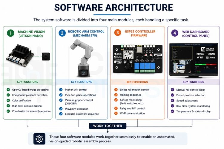
With the overall software architecture established, let's take a closer look at each module and understand how they work together to automate the complete robotic assembly process.
Machine Vision
The machine vision system is implemented on the NVIDIA Jetson Nano using Python, OpenCV, and NumPy to verify each component before it is picked by the robotic arm. A USB camera mounted near the end effector captures images of the component tray, which are first undistorted using camera calibration parameters and then cropped to a predefined Region of Interest (ROI). The ROI is converted from the BGR color space to HSV, where color thresholding is applied to generate a binary mask of the required component. Morphological operations are then used to remove image noise, followed by contour detection and area filtering to accurately identify the target component and determine its position.
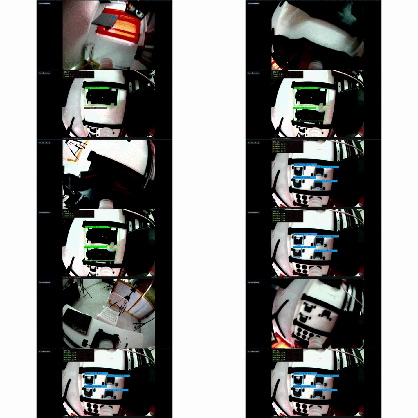
Once the required component is successfully detected, the software loads the corresponding predefined joint angles from a JSON configuration file instead of calculating robot trajectories in real time. These waypoint files contain the pickup, inspection, and placement positions that were manually taught during system calibration. Using the Elephant Robotics Python API, the robotic arm executes the appropriate movement sequence, activates the vacuum gripper to pick the component, and places it at the assembly station. This combination of machine vision and predefined robot waypoints provides a reliable, repeatable, and efficient vision-guided assembly process.
Robot Arm Control
The MechArm 270 is controlled using the Elephant Robotics Python API, allowing the Jetson Nano to communicate with the robotic arm over the local network. The pickup, placement, inspection, and other required robot positions are first taught and saved as JSON waypoint files using the custom web application developed for this project. During operation, the Python application simply loads the required waypoint from the JSON file and commands the robotic arm to move to that position. This approach makes the robot's movements accurate, repeatable, and easy to modify whenever new assembly positions need to be added or updated. Some of the commonly used API functions in this project are shown below.
| Functions | Description |
| MechArm270("COM3", 115200) | Establishes communication with the robotic arm. |
| get_angles() | Returns the current joint angles of all six axes. |
| get_coords() | Returns the current Cartesian coordinates (X, Y, Z, RX, RY, RZ). |
| send_angles([...], speed) | Moves all six joints to the specified angles |
| release_all_servos() | Releases the servo motors for manual positioning |
During the assembly process, the Python program loads the appropriate waypoint from the JSON file based on the current assembly stage. Each waypoint contains the robot's six joint angles, movement speed, linear rail preset, and vacuum gripper state. Once the machine vision system confirms the required component, the corresponding pickup waypoint is executed, followed by activation of the vacuum gripper. After the component is picked, the placement waypoint is loaded to complete the assembly operation. This data-driven approach separates the robot motion from the application logic, making the system modular, easy to maintain, and simple to recalibrate.
{ "name": "chassis-1", "type": "angles", "moveMode": 0, "speed": 100, "rail_preset": "P1", "data": [ -88.16, 1.49, 2.02, -1.40, 4.57, 0.13 ], "vacuum": "none", "vacuum_delay_ms": 300, "delay_ms": 0 }Above is an example of a JSON waypoint containing the predefined joint angles and motion parameters used to control the MechArm 270 during the assembly process.
ESP32 Controller Firmware
The ESP32-S3 Controller Board acts as the dedicated hardware controller for the robotic assembly system, handling all the real-time operations inside the control panel. While the Jetson Nano coordinates the overall assembly process and machine vision, the ESP32 is responsible for controlling the linear rail, reading sensor inputs, and managing the connected peripheral devices. Separating these tasks between the Jetson Nano and the ESP32 creates a more modular architecture, ensuring reliable hardware control without affecting the vision processing.
The firmware is developed using the Arduino framework and handles all the major functions of the controller board. It connects to the Jetson Nano and the web dashboard over Wi-Fi using WebSocket communication, controls the TMC5160 stepper driver to move the linear rail, performs the homing sequence using the limit switch, monitors the temperature and cabinet door sensors, and controls the relay, buzzer, and status indicator lights during system operation.
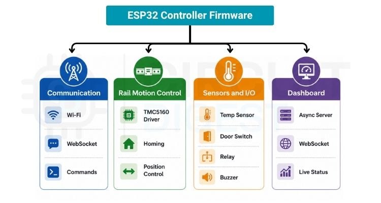
» Communication - The firmware establishes a Wi-Fi connection and exchanges commands and status information with the Jetson Nano through WebSocket communication.
» Motion Control - The firmware controls the TMC5160 stepper motor driver, performs the homing sequence, and accurately positions the linear rail based on the received commands.
» Sensor and Peripheral Control - The firmware continuously monitors the temperature sensor and cabinet door switch and controls the relay, buzzer, and status indicators to ensure reliable system operation.
» Dashboard Interface - The firmware hosts the asynchronous web server and updates the web dashboard with live information such as rail position, controller temperature, and system status while also accepting manual control commands.
Web Dashboard
The web dashboard is divided into three dedicated pages, each designed for a specific task. Developed using Flask, HTML, CSS, and JavaScript, the dashboard communicates with the backend through Flask-SocketIO (WebSockets), enabling real-time data exchange without refreshing the page. This architecture allows the operator to seamlessly switch between live system monitoring, machine vision configuration, and robotic arm control, while continuously receiving updates from the Jetson Nano, ESP32 Controller Board, and MechArm 270 over the local Wi-Fi network.
1. Main Dashboard
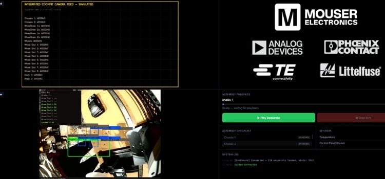
The Main Dashboard serves as the primary interface during the assembly process. It displays the live camera feed with OpenCV detection overlays, assembly progress, component verification status, sensor information, and system logs in real time. From this page, the operator can start or stop the complete assembly sequence while continuously monitoring the status of the robotic arm and the control panel.
2. Camera Settings & ROI Configuration
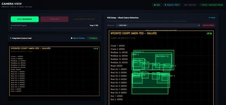
The Camera Settings page is used to configure the machine vision system. It allows the operator to define the Region of Interest (ROI) for each component by drawing bounding regions directly on the live camera feed. These ROI coordinates are saved and later used by the OpenCV detection algorithm to inspect the correct locations during the assembly process. The page also provides options for camera tuning and visualization of the detection overlays.
3. MechArm & Rail Control
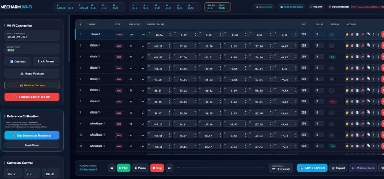
The MechArm & Rail Control page is primarily intended for system setup and calibration. It provides manual control over the robotic arm and linear rail, allowing users to jog individual joints, move the rail to predefined positions, create and edit waypoints, configure robot speeds, and save or export the recorded positions as JSON files. This interface simplifies robot calibration and enables quick modifications to the assembly sequence without changing the main Python application.
While this article provides an overview of the system architecture and software workflow, the complete source code, PCB design files, and implementation details are available on the project's GitHub repository. If you're interested in understanding the firmware, machine vision algorithms, or web dashboard in greater depth, be sure to check out the repository.
GitHub Repository
While this article provides an overview of the system architecture and software workflow, the complete source code, PCB design files, and implementation details are available on the project's GitHub repository. If you're interested in understanding the firmware, machine vision algorithms, or web dashboard in greater depth, be sure to check out the repository.


Challenges Faced
Building a robotic assembly system involved much more than simply integrating different hardware components. Since the robotic arm, machine vision system, linear rail, and controller board all operate together, achieving reliable synchronization requires careful testing and calibration. Throughout the development process, several practical challenges were encountered and gradually resolved through hardware and software improvements.
Some of the key challenges included:
- Robot Calibration: Precisely recording and tuning the pick-and-place positions to ensure consistent and repeatable movements.
- Machine Vision Accuracy: Maintaining reliable colour detection under varying lighting conditions and correctly defining the ROI for each component.
- Linear Rail Alignment: Aligning the rail with the robotic arm to ensure accurate positioning across all component trays.
- System Synchronisation: Coordinating communication between the Jetson Nano, MechArm 270, and ESP32 controller to execute the assembly sequence without timing issues.
- Vacuum Pickup Reliability: Optimising the vacuum delay and pickup height to ensure small 3D-printed components were picked consistently.
- Cable Management: Routing power, communication, and pneumatic tubing neatly through drag chains to prevent interference with the robot's movement.
Future Improvements
While the current system uses ROI-based color detection with OpenCV for component verification, future versions could leverage the GPU capabilities of the Jetson Nano to run Edge AI models such as YOLO for real-time object detection. This would eliminate the need to manually define ROIs, making the system more robust against changes in lighting, component orientation, and tray layout while allowing it to identify multiple components automatically.
Another major improvement would be dynamic pick-and-place. Instead of relying on predefined pickup positions stored as JSON waypoints, the machine vision system could estimate the exact position and orientation of each component and generate the robot's pickup coordinates in real time. This would enable the robotic arm to locate and pick components regardless of where they are placed within its workspace, making the assembly system significantly more flexible and closer to modern industrial automation solutions.