

Nowadays, visual indication is a must-have feature for any electronic device, which will make user interaction much easier. There are multiple ways to implement the visual indication, from simple light indications to LCDs or even holograms. Today, we will be talking about such a device, which has been used in the industry for decades – the Seven Segment Display. The 7 segment display Arduino interface is one of the most fundamental projects for electronics beginners. In this comprehensive tutorial, you'll learn everything about 7 segment display Arduino code, circuit connections, and practical applications.
The seven segment displays are designed for displaying numeric values. You can find them anywhere, from instruments to space shuttles. They are the most practical way to display numeric values in your Arduino Projects. They are cheap and easy to use. Not only that, they are highly readable in any light condition, unlike LCDs. You can find them in many everyday usages, like counters or token systems, etc.
Table of Contents
Required Components
| Component | Quantity | Specifications | Purpose |
| Arduino Uno | 1 | ATmega328P based | Microcontroller board |
| 7 Segment Display | 1 | Common Cathode/Anode | Display unit |
| Resistors | 8 | 330Ω | Current limiting |
| Breadboard | 1 | Full size | Circuit connections |
| Jumper Wires | 10+ | Male to Male | Connections |
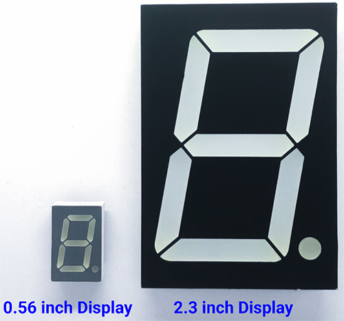
And here is a small simulation showing the Seven Segment Interface. The Arduino will count from 0 to 9 and repeat. The value will be displayed on the seven-segment display. Seven-segment displays are available in various sizes and colours. They are available from 0.28 inches to 18 inches, and even bigger sizes are available for industrial usage. The most commonly used display size is 0.56 inches.
Understanding 7 Segment Display Pinout
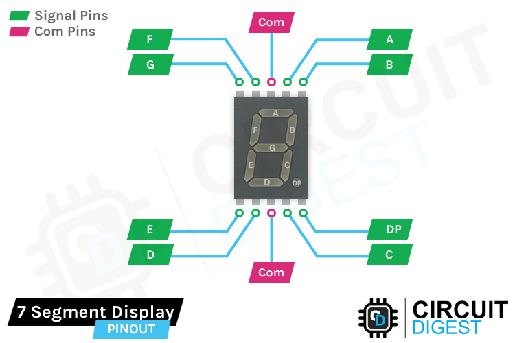
The 7 segment display pinout is crucial for proper Arduino interfacing. As the name suggests, the seven-segment display consists of seven LEDs, which are arranged in a particular order to form the digit eight. And most common modules will come with an additional LED to indicate the decimal point. This will be useful when using multiple display modules to display a decimal number. Each one of these LEDs is arranged in a specific order as a segment, and one of its pins is brought out of the plastic package. The other LED pins are connected and wired to form a common pin.
Standard Pin Configuration
- Segments A-G: Individual LED anodes/cathodes for each segment
- Common Pin: Shared connection for all LEDs (pin 3 or 8)
- Decimal Point (DP): Additional LED for decimal indication
By forward-biasing the appropriate pins of LED segments in a particular order, we can generate the character pattern of a desired number on the display. The 7 segment display Arduino working principle allows us to display the numbers from 0 to 9 on the display. In the above image, we have highlighted the eight data pins in green and the common pin in pink.
Types of Seven Segment Displays
Seven segment displays are mainly categorised into two types, Common Cathode (CC) and Common Anode (CA). This classification is done based on which pin of the LEDs is connected to the common pin. If the Anodes of these LEDs are connected, then it’s called a Common Anode display. And if the Cathode is connected, then they are called Common Cathode displays.
Common Cathode Displays
In a Common Cathode (CC) display, all the cathodes of the LEDs are connected to the common pin. This common pin is then connected to the ground rail of the circuit. The individual LEDs can be activated by applying a high pulse or a logic 1 signal to the corresponding pin.
In the above image, you can see the basic working of the seven-segment. The common pin is connected to the GND, and each data pin is connected to VCC through a switch. When a switch is pressed, the corresponding LED will be forward-biased, and the segment will light up. On the right side, you can see the simplified diagram of a seven-segment display.
Common Anode Displays
In a Common Anode (CA) display, all the anodes of the LEDs are connected to the common pin. This common pin is then connected to the positive rail of the circuit. The individual LEDs can be activated by applying a low pulse or a logic 0 signal to the corresponding pin.
In the above image, you can see the basic working of the seven-segment. The common pin is connected to the VCC, and each data pin is connected to GND through a switch. When a switch is pressed, the corresponding LED will be forward-biased, and the segment will light up. On the right side, you can see the simplified diagram of a seven-segment display.
Seven Segment Display Truth Table
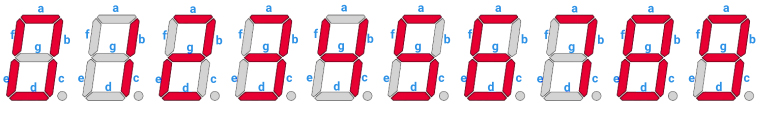
To display a number or pattern, we must activate the corresponding pins with the appropriate signal, i.e. for Common Cathode display Logic 0 or LOW and for Common Anode display Logic 1 or HIGH. By this method, we can display various digits from 0 to 9. Here is the character map for each character.
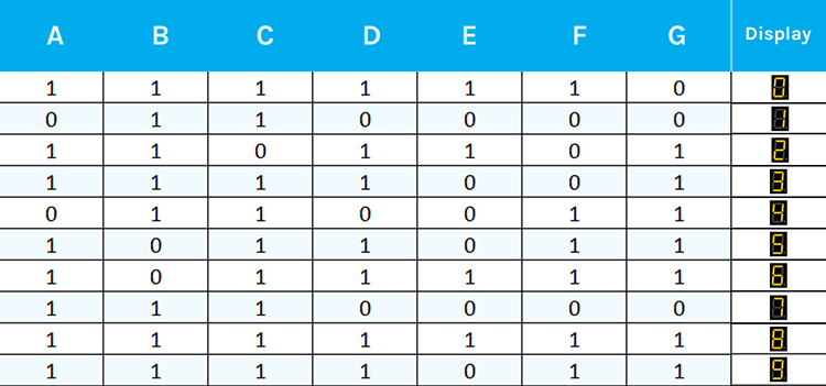
And here is the truth table for the Common Cathode display. For the Common Anode display, the signals will be inverted.
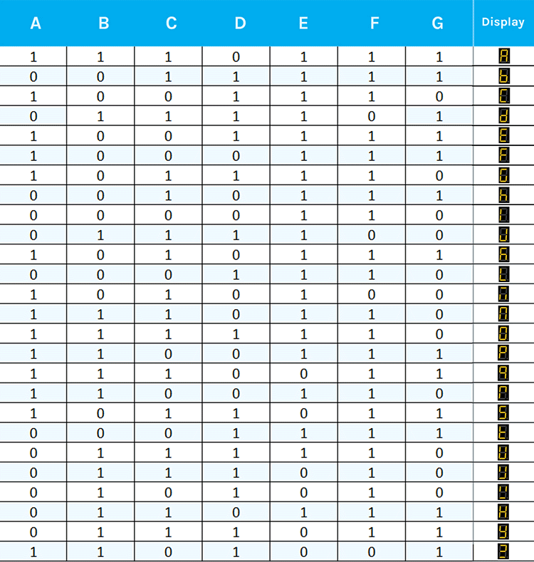
Even though the seven segments are designed to display numbers, we can also display letters using them. Here is the truth table for the alphabet.
7 Segment Display Arduino TinkerCAD Simulation
Let’s simulate the circuit on ThinkerCAD before testing it on the breadboard. Here is the Thinkercad simulation for interfacing the seven-segment display with Arduino. Before building the physical circuit, test your 7 segment display Arduino TinkerCAD simulation.
Click on the start simulation button to test the circuit. The Tinkercad code for the interfacing seven-segment display with Arduino will show numbers 0-9 on the display. If you want to edit the code, please click the code button and modify as needed.
Benefits of TinkerCAD Simulation
- Evaluate circuit performance before creating real hardware.
- Troubleshoot software bugs in a safe environment.
- Try with varying values for components.
- Publish your created projects for the community.
- Engage in a more hands-on learning of Arduino programming.
7 Segment Display Arduino Circuit Diagram
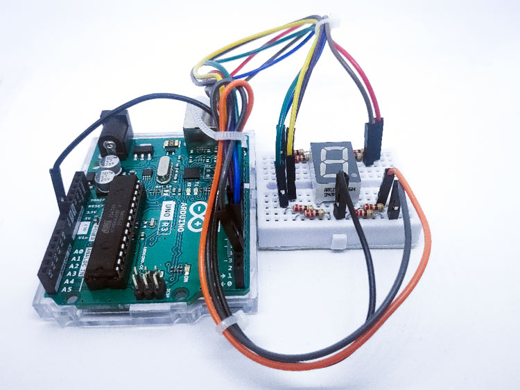
Now let’s see how we can drive a seven-segment display with an Arduino. For that, let’s start by placing the display module on a breadboard with the decimal point facing downwards. Then wire up each pin as per the connection diagram below. In this tutorial, we will be using a Common Cathode display. The 7 segment display Arduino circuit diagram shows the complete wiring setup for interfacing a common cathode display with Arduino Uno.

Connect either of the common pins (seven-segment pin 3 or 8) to the ground. And connect the rest of the pins to D2 to D9 of the Arduino through a current-limiting resistor, as per the connection diagram. Just like driving an LED, it is preferable to use these current-limiting resistors to increase the display life. Choose these values depending on the display colour and size. Here we will be using a 330 ohms resistor, which will provide around 10mA current for the LEDs.
And here is the actual circuit.
Arduino Code for Seven Segment Display
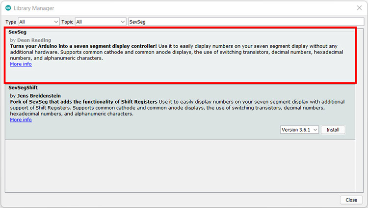
Now let’s get to the coding part. For this tutorial, we will need to install several Arduino libraries, and this can be done directly via the library manager. To install the libraries, navigate to the Arduino IDE > Sketch > Include Library > Manage Libraries… Wait for the Library Manager to download the library's index and update the list of installed libraries. Then search for SevSeg and install the SevSeg library by Dean Reading. The following 7 segment display Arduino code demonstrates how to control a common cathode display using the SevSeg library:
Once you have installed the library, create a new sketch and copy our Arduino example code to it. Our example code will count from 0 to 9 and reset back to 0. And the process will repeat. You can see the numbers are counting up on the display.
Method 1: Using SevSeg Library (Recommended)
#include "SevSeg.h"
SevSeg sevseg;
void setup()
{
      //Set to 1 for single-digit display
      byte numDigits = 1;
      //defines common pins while using multi-digit display. Left for single digit display
      byte digitPins[] = {};
      //Defines Arduino pin connections in order: A, B, C, D, E, F, G, DP
      byte segmentPins[] = {9,8, 7, 6, 5, 4, 3, 2};
      byte displayType = COMMON_CATHODE; //Use COMMON_ANODE for Common Anode display
      bool resistorsOnSegments = true; //‘false’ if resistors are connected to common pin
      //Initialize sevseg object. Use COMMON_ANODE instead of COMMON_CATHODE for CA display
      sevseg.begin(displayType, numDigits, digitPins, segmentPins, resistorsOnSegments);
      sevseg.setBrightness(90);
}
void loop()
{
   //Display numbers 0-9 with 1 seconds delay
   for(int i = 0; i <= 10; i++)
   {
     if (i == 10)
{
 i = 0;
}
     sevseg.setNumber(i);
     sevseg.refreshDisplay();
     delay(1000);
   }
}
Code Explanation
In the sketch, we have added the SevSeg library and created an object with the name sevseg. We will be using this object to control the display with the help of the SevSeg library.
#include "SevSeg.h"
SevSeg sevseg;
In the setup() function, we are initialising the SevSeg library. To initialise the library, we will be using the following variable.
- The first one is numDIgits; this variable indicates the number of displays connected. We are using only one display, so for us, this variable is 1.
- The second variable is digitPins; this variable represents the Arduino pins connected to the common pins of multi-segment displays. Since we are only using one segment display, we are connecting the common pin to the ground. So, we can leave this blank.
- The Variable segmentPins; contain the Arduino PINs to which the segment pins are connected. The pin connection is in the following order: a, b, c, d, e, f, g, dp.
- displayType indicates the display type, whether common anode or common cathode.
- And the resistors OnSegment indicate whether the current limiting resistors are connected to the segment pins or the common pin.
Method 2: Manual Control (Educational)
void setup()
 {
      //Set to 1 for single digit display
      byte numDigits = 1;
      //defines common pins while using multi-digit display. Left for single digit display
      byte digitPins[] = {};
      //Defines arduino pin connections in order: A, B, C, D, E, F, G, DP
      byte segmentPins[] = {9,8, 7, 6, 5, 4, 3, 2};
      byte displayType = COMMON_CATHODE; //Use COMMON_ANODE for Common Anode display
      bool resistorsOnSegments = true; //‘false’ if resistors are connected to common pin
      //Initialize sevseg object. Use COMMON_ANODE instead of COMMON_CATHODE for CA display
      sevseg.begin(displayType, numDigits, digitPins, segmentPins, resistorsOnSegments);
      sevseg.setBrightness(90);
 }
And in the loop function, the variable 'i is counting from 0 to 9 and displays this value with the help of the setNumber and refreshDisplay functions. The counting interval is set to 1 second using the delay function.
Technical Summary and GitHub Repository
The Technical Summary highlights the project’s design, workflow, and core functionality in a concise manner. The GitHub Repository complements it with complete code, schematics, and resources for hands-on replication.


Troubleshooting Common Issues
| Problem | Possible Cause | Solution |
| Display not lighting up | Wrong common pin connection | Check CC/CA type and wire common pin correctly |
| Segments too dim | High resistance values | Use lower value resistors (220Ω-330Ω) |
| Wrong digits displayed | Incorrect pin mapping | Verify segment pin connections with datasheet |
| Flickering display | Loose connections | Check breadboard connections and wiring |
| LEDs burning out | Missing current limiting resistors | Always use appropriate resistors (330Ω recommended) |
Commonly Asked Questions about Seven Segment Displays
⇥ 1. What are the size and colour options available for seven-segment displays?
The seven-segment displays are available in various sizes and colours. They are available from 0.28 inches to 18 inches, and even bigger sizes are available for industrial usage. The most commonly used sizes are 0.28 inches, 0.36 inches and 0.56 inches.
⇥ 2. Are there multi-segment displays available?
Yes, there are multi-segment displays available. From 2 segments onwards. You can choose whichever is suitable for you.
⇥ 3. Are the current-limiting resistors necessary?
The display will work without the current-limiting resistors. But it is recommended to use those current-limiting resistors to increase the life of those displays. They will limit the current through the LED below the recommended value so that the LED won’t burn out and last longer.
⇥ 4. How do common cathode and common anode displays differ?
In common cathode displays, all of the cathodes of LEDs are connected (to ground), whereas in common anode displays, all anodes are connected (to VCC). This influences the levels of logic required for lighting segments.
⇥ 5. Why do 7-segment displays require current-limiting resistors?
Current-limiting resistors are used to prevent excessive current from flowing through LEDs, which can otherwise cause damage. For example, LEDs can burn out if they are not loaded with resistors and experience the potential for overcurrent. Common values are 220Ω and 470Ω.
⇥ 6. How many Arduino pins are required for a single 7-segment display?
A single 7-segment display requires 8 Arduino pins (7 segments, plus the decimal point) and 1 common pin connection to power or ground. Therefore, an overall total of 8 digital pins is required to control the segment outputs.
⇥ 7. How many 7-segment displays can I connect to an Arduino?
An Arduino Uno has 14 digital pins, so directly connecting the displays would at the very most be 1-2 displays. You could utilise multiplexing or shift registers (such as 74HC595) to run more displays efficiently with fewer control pins.
⇥ 8. How do I make a 7-segment display brighter?
You can adjust brightness by changing the values of the resistors, using PWM signals, or by adjusting the supply voltage. The SevSeg library has a great function setBrightness that takes a value from 0-100% to adjust brightness.
Learning to interface a 7 segment display Arduino will allow you to take on many more electronics projects. In this tutorial, you covered everything from what's in the 7 segment display pinout to implementing it in an advanced project. With repetition and play, you will easily be making some excellent 7 segment display Arduino projects and demonstrating more skills in electronics.
Projects Using Seven Segment Displays
Previously, we at Circuit Digest have built a lot of Electronics Projects with detailed step-by-step instructions. Once you master basic interfacing, explore these advanced 7 segment display projects:

Interfacing a Seven-Segment Display with Raspberry Pi
In this tutorial, you will find a Circuit Diagram, Complete code, and a step-by-step guide to interface a seven-segment display with Raspberry Pi.

Arduino 7 Segment Display Clock
Build a Digital clock by multiplexing four 7-segment displays using Arduino UNO and displaying the time in HH: MM format.

7-Segment Counter using 555 Timer IC
Digital counters are needed everywhere in this digital world, so build your own 7-Segment Counter using a 555 Timer IC

Interfacing a Seven-Segment Display with ARM7-LPC2148
Learn how to Interface a Seven-Segment Display with ARM7-LPC2148. Here you can find the Complete Circuit Diagram, Code, and Step-by-step guide

2 Digit Object/Product Counter Circuit
We designed a simple object counter circuit without using any microcontroller. Object counters count objects or products automatically and so reduce human efforts.
Complete Project Code
#include "SevSeg.h"
SevSeg sevseg;
void setup()
{
  //Set to 1 for single-digit display
  byte numDigits = 1;
  //defines common pins while using multi-digit display. Left for single digit display
  byte digitPins[] = {};
  //Defines Arduino pin connections in order: A, B, C, D, E, F, G, DP
  byte segmentPins[] = {9,8, 7, 6, 5, 4, 3, 2};
  byte displayType = COMMON_CATHODE; //Use COMMON_ANODE for Common Anode display
  bool resistorsOnSegments = true; //‘false’ if resistors are connected to common pin
  //Initialize sevseg object. Use COMMON_ANODE instead of COMMON_CATHODE for CA display
  sevseg.begin(displayType, numDigits, digitPins, segmentPins, resistorsOnSegments);
  sevseg.setBrightness(90);
}
void loop()
{
   //Display numbers 0-9 with 1 seconds delay
   for(int i = 0; i <= 10; i++)
   {
     if (i == 10)
{
 i = 0;
}
     sevseg.setNumber(i);
     sevseg.refreshDisplay();
     delay(1000);
   }

0,1,2,3 dont works correctly