
In this project, we integrate the GP2Y0D810Z0F distance sensor to the Arduino UNO and display the detection result on the 16x2 I2C LCD screen and the Serial Monitor. The sensor is designed for quick on and off detection within a set distance of about 10 cm. This is great for detecting obstacles, sensing presence, and handling simple automation jobs. At the end of this GP2Y0D80Z0F module with Arduino Uno project, you’ll have a system that tells you if something is within 10 cm and displays that info in real time. In the process, you will also learn how to wire I2C devices properly, how to read digital sensors effectively, and how to make small decisions that boost the system’s reliability and ease of use. To get started on the infrared sensors checkout the project on Interfacing IR Proximity Sensor with Arduino
Table of Contents
- Understanding the GP2Y0D80Z0F Distance Sensor
- How the GP2Y0D80Z0F Sensor Works
- └ GP2Y0D80Z0F Technical Specifications
- Why Choose GP2Y0D80Z0F?
- Pin Configuration
- Hardware Components Required
- Circuit Diagram
- └ Complete Pin Mapping Reference
- How the GP2Y0D80Z0F Arduino System Works
- Code Explanation
- Real-World Applications
- Troubleshooting
- GitHub Repository
Understanding the GP2Y0D80Z0F Distance Sensor
The GP2Y0D810Z0F is a digital infrared proximity sensor that doesn’t provide a continuous voltage signal based on distance, but instead gives a clear HIGH or LOW signal that changes when an object comes within its set range, which is around 10 cm. It sends out infrared light and then detects the light that bounces back from nearby objects. If the reflected light is strong, the sensor’s output will be LOW, showing that something has been detected. Similar to other infrared sensors, how well it works can depend on the material, colour, shine, and angle of the object being detected. Very dark or absorbent surfaces may not reflect much infrared light, while shiny surfaces can make the sensor detect things from farther away. The sensor has a narrow viewing angle, which helps prevent false readings from objects not directly in front, but accurate placement and alignment are still important for reliable performance.
How the GP2Y0D80Z0F Sensor Works
Infrared light is transmitted by the sensor, and then the sensor, through a receiver, measures the brightness/intensity of infrared light reflected to it from nearby objects. When enough infrared light is returned (reflected) to the sensor’s receiver, indicating that there is an object within the 10 cm detection area, the output of that sensor switches to a low level. If there is no object detected, or the detected object is past the minimum detection requirement of 10 cm, the value of the sensor’s output remains at a high level.
GP2Y0D80Z0F Technical Specifications
| Parameter | Specification |
| Detection Type | Digital (Binary output) |
| Detection Distance | ~10 cm (fixed threshold) |
| Operating Voltage | 2.7V – 6.2V DC |
| Output Signal | LOW (object detected) / HIGH (no object) |
| Response Time | Fast (milliseconds) |
| Viewing Angle | Narrow (reduces false triggers) |
| Interface Type | 3-pin header (GND, VIN, OUT) |
Why Choose GP2Y0D80Z0F?
✓ Simple digital output eliminates complex signal processing requirements
✓ Fast response time enables real-time reactive systems
✓ Low power consumption suitable for battery-powered applications
✓ Easy integration with relays, buzzers, LEDs, and other actuators
✓ Compact size fits in space-constrained installations
✓ Cost-effective solution for binary proximity detection needs
GP2Y0D80Z0F Distance Sensor Pin Configuration
The image below shows the pinout of the GP2Y0D810Z0F Distance Sensor module. Understanding the GP2Y0D80Z0F distance sensor pinout is crucial for correct wiring and successful project implementation.
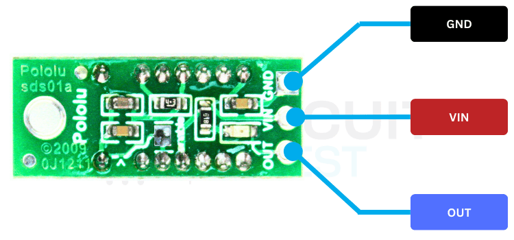
The carrier board exposes a 3-pin header interface; the pinout is explained in the table below.
| Pin | Name | Description |
| 1 | GND | Ground reference |
| 2 | VIN | Power input (2.7 V – 6.2 V) |
| 3 | OUT | Digital output (LOW = object detected) |
Hardware Components Required to Interface GP2Y0D810Z0F with Arduino UNO
The image below shows the list of components used to interface the Distance sensor with Arduino Uno
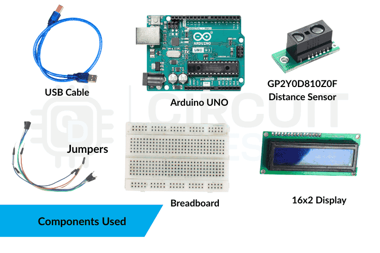
The list of required components is listed in the table below.
| Component | Quantity | Role |
| Arduino UNO | 1 | Main controller |
| GP2Y0D810Z0F | 1 | A sensor to detect the distance |
| 16x2 I2C LCD | 1 | Displays the texts |
| Breadboard | 1 | For easy prototyping |
| Jumper Wires | Several | Electrical connections |
| USB Cable | 1 | Uploading sketch and power |
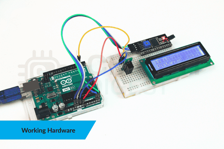
Circuit Diagram on Interfacing GP2Y0D810Z0F Distance Sensor with Arduino UNO
The following wiring diagram illustrates the complete electrical connections for interfacing the GP2Y0D80Z0F sensor with Arduino Uno.

Complete Pin Mapping Reference
| Device | Device Pin | Arduino Uno Pin | Wire Color Suggestion |
| GP2Y0D80Z0F Sensor | GND | GND | Black |
| VIN | 5V | Red | |
| OUT | Digital Pin 2 | Yellow/Orange | |
| 16x2 I2C LCD | GND | GND | Black |
| VCC | 5V | Red | |
| SDA | A4 (SDA) | Blue | |
| SCL | A5 (SCL) | Green |
How the GP2Y0D80Z0F Arduino System Works
The sensor continuously sends out infrared light and measures how much of that light is reflected. When a reflective object is within its set detection range, it returns a low signal. The Arduino constantly checks this signal, interpreting a low signal as "Object detected" and a high signal as "No object." It then updates both the LCD and the serial console. Since the output has only two possible states, it doesn't show how close the object is, just whether it's within or outside the 10 cm range. To keep the interface smooth and stable, the code includes a short delay between updates. In more advanced setups, you could use methods like debouncing or a state machine to update the display only when the sensor's state changes, which helps avoid flickering and lowers I2C activity. This simple approach makes the system easy to understand, test, and modify.
GP2Y0D80Z0F Arduino Code Explanation
The following sections break down the GP2Y0D80Z0F module with Arduino Uno code implementation, explaining each component's purpose and functionality. The code starts by loading the required libraries for the LCD:
Required Libraries
#include <Wire.h>
#include <LiquidCrystal_I2C.h>
Then the sensor pin is defined:
Pin Configuration and LCD Initialization
const int SENSOR_PIN = 2;In the setup section, serial communication is started, the sensor pin is configured as an input, and the LCD is initialized using commands like:
Setup Function Configuration
lcd.begin();
lcd.backlight();
A short startup message is shown on the display just to confirm that everything is powered and responding correctly.
The main logic sits inside the loop. The Arduino continuously reads the sensor output using:
int sensorState = digitalRead(SENSOR_PIN);The important thing to understand is that the sensor itself decides whether something is within 10 cm. It sends LOW when an object is close and HIGH when nothing is detected. The code simply checks this value and updates the LCD accordingly using blocks like:
lcd.print("Object Detected");or
lcd.print("No Object");At the same time, the same status message is printed to the Serial Monitor, so testing becomes easier. A small delay at the end keeps the display steady without rapid flickering. The overall program stays clean and minimal because the sensor already handles all the distance calculations internally. The Arduino just reads one digital pin and shows the result.
Real-World Applications of GP2Y0D80Z0F Proximity Sensor
- It's great for small robots, acting as a fast obstacle detector to help stop or turn before a collision happens.
- It's also useful in kiosks or smart bins, where it can trigger a screen to wake up or open a lid when someone approaches without needing to touch it.
- On conveyor systems, it helps detect the presence of items, start or stop actuators, or count objects passing a checkpoint.
- It can also act as a near-field safety guard around machine inlets, alerting when hands or tools get too close.
- Since it outputs digital signals, it integrates easily into bigger systems, making it simple to connect with relays, buzzers, LEDs, or other sensors.
- Multiple sensors can be used together to create simple detection zones around a device or workspace.
Troubleshooting GP2Y0D80Z0F Sensor Issues
| Issue | Possible Causes | Fix |
| The LCD shows nothing | Address mismatch | Try switching between 0x27 and 0x3F |
| Contrast too low | Adjust the contrast trimpot on the I2C backpack | |
| Incorrect I2C wiring | Ensure SDA → A4 and SCL → A5 on Arduino Uno | |
| The Serial Monitor is blank | Wrong baud rate | Set Serial Monitor to 9600 baud |
| Wrong COM port | Select the correct COM port and ensure the board is connected | |
| Sensor never detects / always detects | Incorrect wiring | Check VCC, GND, and OUT; loose grounds cause unstable logic |
| Output pin floating | Add 10 kΩ pull-up to 5 V, or use INPUT_PULLUP and invert logic | |
| Poor target reflectivity | Use a light-colored object; avoid dark or angled surfaces | |
| Flickering display / unstable readings | Frequent LCD clearing | Update the LCD only when the state changes |
| Delay too short | Use a 300–500 ms delay for stability | |
| Power noise | Place a decoupling capacitor across 5V–GND; avoid motor power sharing | |
| I2C issues | Long or noisy wires | Keep SDA/SCL short and away from high-current lines |
| Loose jumper wires | Reseat connectors; intermittent contact causes random failures |
Connecting the GP2Y0D810Z0F proximity sensor to an Arduino Uno creates a reliable and easy-to-implement detection system with fast response times. The sensor's digital signal simplifies programming by providing a straightforward on/off output when objects come within 10 cm, while the LCD displays this status information clearly and concisely. Performance enhancements can include updating the screen only during state transitions, implementing interrupt-driven detection for quicker reactions, or securing the sensor with a fixed mount for consistent alignment. This setup serves as an excellent foundation for contactless interfaces, obstacle-detecting robotics, and presence-activated automation systems. The design is highly expandable, offering opportunities to integrate additional sensors, establish multiple detection areas, or connect with motors and wireless modules for more advanced applications. Explore a curated collection of arduino projects ideas with complete circuits and source code.
GitHub Repository
Access the complete project repository containing Arduino source code, wiring diagrams, demonstration videos, and additional documentation through our GitHub repository:


Frequently Asked Questions: Interfacing gp2y0d80z0f sensor with Arduino Uno
⇥ 1. What is the GP2Y0D80Z0F distance sensor?
The GP2Y0D80Z0F is a digital proximity infrared sensor for detecting objects in proximity (within a 10 cm distance). It differs from analog distance sensors in that it only produces a digital high/low signal, which makes it relatively easy to use for many of applications that require the presence of an object without needing to know the distance to the object.
⇥ 2. How do I connect the GP2Y0D80Z0F to my Arduino UNO?
To connect the GP2Y0D80Z0F, you will need to connect the: VIN pin of the GP2Y0D80Z0F to the 5V pin of the Arduino, the GND pin of the GP2Y0D80Z0F to the GND pin of the Arduino, and the OUT pin of the GP2Y0D80Z0F to Digital Pin 2 of the Arduino. The GP2Y0D80Z0F operates at 2.7V to 6.2V voltage and produces a digital output signal (LOW when an object is detected within 10cm, HIGH when there are no objects detected).
⇥ 3. What is the detection range of the GP2Y0D80Z0F sensor?
The detection range of the GP2Y0D80Z0F is approximately 10 cm (4 inches). The detection range is factory-calibrated and cannot be changed. The GP2Y0D80Z0F provides binary detection output: LOW when an object is present within the 10 cm detection range, HIGH when there are no objects detected within the 10 cm detection range or the objects fall outside of the 10 cm distance of detection.
⇥ 4. What can cause my GP2Y0D80Z0F sensor to produce multiple readings that don’t match one another?
There can be many possible reasons why a sensor will produce unpredictable readings. The most common causes for a sensor to produce poor quality readings are due to low reflective properties of the surface being detected (e.g., dark color or dull finish), loose connections on the wiring harnesses, floating output voltage, or noise on the power supply. Some suggestions to fix these problems are to use light-colored test surfaces, check all wire connections, add a 10k ohm pull-up resistor to the output signal line, and add a decoupling capacitor placed across the power pins.
⇥ 5. How do I identify the GP2Y0D80Z0F distance sensor pinout connections?
The GP2Y0D80Z0F has a total of three pins in a header configuration: Pin 1 (ground reference), Pin 2 (power supply input rated at 2.7 to 6.2 volts), and Pin 3 (digital output). When an object is detected in range, pin 3’s output goes LOW (0V), and when an object is out of range, pin 3’s output goes HIGH (supply voltage).
⇥ 6. Do GP2Y0D80Z0F sensors have the ability to measure actual distance, like ultrasonic distance measuring devices?
No, the GP2Y0D80Z0F is considered to be a binary proximity sensor and only produces a signal that indicates whether or not an object is present within a distance of 10 centimetres. The GP2Y0D80Z0F has no capability of measuring physical distances in the same way that ultrasonic sensors do. For measuring distance, consider using an analog IR distance sensor such as the GP2Y0A21YK, or an ultrasonic distance sensor like the HC-SR04, instead.
⇥ 7. Which Arduino libraries do I have to use to convert Arduino Uno code to control the GP2Y0D80Z0F module?
The sensor doesn't require special library support. It uses the built-in digitalRead() function from the Arduino IDE. The following LCD display libraries will need to be included for display on an LCD: The built-in Wire.h library (provided with the Arduino IDE) and a second library, LiquidCrystal_I2C.h, (also included in the Arduino IDE) must be installed using the Library Manager in the Arduino IDE before programming. The sensor has a simple digital output, which makes it possible to operate without relying on any complex libraries.
Conclusion
Interfacing the GP2Y0D80Z0F distance sensor with Arduino Uno project we worked on created a versatile, reliable proximity detection system that can be used for all kinds of robotics, automation, and interactive displays. The GP2Y0D80Z0F distance sensor has a digital output that makes programming simpler and more reliable for objective detection (within 10 cm) quickly and consistently.
This tutorial has shown the complete hardware assembly of the GP2Y0D80Z0F distance sensor with Arduino Uno as well as all pinout configurations, functional code examples, and troubleshooting strategies. Using an LCD to get visual feedback and the Serial Monitor for debugging will provide you with many different methods to verify and troubleshoot your code during development and when deploying a product.
Arduino Projects Using IR Sensors
Explore practical Arduino projects using IR sensors with step-by-step guides, wiring diagrams, and example code.

Interfacing the PCA9306 Module with Arduino Uno
Learn how to interface the PCA9306 I²C level shifter with an Arduino Uno - complete with wiring guide, Arduino code examples, and troubleshooting tips.

How to Build a Speed Sensor using Arduino?
Build a Speed Sensor using Arduino with IR speed sensors to accurately measure the speed of moving objects.

How to Build a Bidirectional Visitor Counter using Arduino
Build a Bidirectional Visitor Counter using Arduino and IR sensors to track entry and exit movements with real-time counting on an LCD display.
Complete Project Code
#include <Wire.h>
#include <LiquidCrystal_I2C.h>
// GP2Y0D810Z0F sensor pin
const int SENSOR_PIN = 2;
// Initialize LCD (address 0x27, 16 columns, 2 rows)
// If 0x27 doesn't work, try 0x3F
LiquidCrystal_I2C lcd(0x27, 16, 2);
void setup() {
 // Initialize serial communication
 Serial.begin(9600);

 // Initialize sensor pin
 pinMode(SENSOR_PIN, INPUT);

 // Initialize LCD
 lcd.begin();
 lcd.backlight();

 // Display startup message
 lcd.setCursor(0, 0);
 lcd.print("Distance Sensor");
 lcd.setCursor(0, 1);
 lcd.print("Initializing...");
 delay(2000);
 lcd.clear();
}
void loop() {
 // Read sensor state (LOW = object detected, HIGH = no object)
 int sensorState = digitalRead(SENSOR_PIN);

 // Clear LCD
 lcd.clear();

 if (sensorState == LOW) {
   // Object detected within 10cm
   lcd.setCursor(0, 0);
   lcd.print("Object Detected");
   lcd.setCursor(0, 1);
   lcd.print("Distance: <10cm");

   Serial.print("Status: Object detected | Distance: <10cm");
   Serial.println();
 } else {
   // No object detected
   lcd.setCursor(0, 0);
   lcd.print("No Object");
   lcd.setCursor(0, 1);
   lcd.print("Distance: >10cm");

   Serial.print("Status: No object | Distance: >10cm");
   Serial.println();
 }

 delay(200);
}
