
Have you ever noticed how shopping malls, parking lots, or event venues seem to track the number of people or cars present inside? You might think they use an AI camera to count them, but in reality, a simple sensor based system can efficiently accomplish this task. By placing sensors at a single entry/exit point, these systems can detect movement direction and track the number of people inside.
In this Arduino project tutorial, I will show you how to build a simple bidirectional counter system that detects whether a visitor is entering or exiting a pathway. We will count the entries and exits using arduino and display the total visitor count on a LCD display. This is a fun weekend DIY project which you can build with a handful of easily available components and a few lines of code. You can also improvise on this project to build an automatic room light controller based on the number of visitors in the room.
By the end of the guide, you’ll not only have a fully functional bidirectional counter but also gain hands-on experience with IR sensors,16x2 LCD display, Arduino programming, and some hardware/software hacks tips. Let’s get started.
Table of Contents
- How does an IR sensor detect the direction of visitor?
- Components Required
- Block Diagram for Bidirectional Visitor Counter
- Circuit Diagram
- └ Tips to Avoid False Trigger
- Arduino code for Bidirectional Counter System
- └ Including HeaderFiles
- └ Create an LCD Object
- └ Global Variable Declaration
- └ updateDisplay() Function to Update the count on Display
- └ Setup() Function to Initialize GPIO Pins and Display
- └ Loop() Function to continuously check for Sensor Trigger
- Uploading Code to Arduino UNO
- Demo of Bidirectional Counter System using Arduino
- └ Arduino Bidirectional Visitor Counter - Working Video
- GitHub Repo with Code and Circuit
- Similar Projects
How does an IR sensor detect the direction of visitor?
Basically, IR sensors detect objects by emitting infrared(IR) light, if there is an object in front of the sensor, this IR light gets reflected back to the sensor from the object, allowing the sensor to detect the object. However, when we use the pair of IR sensors, we can not only detect the presence of the moving object but also detect the direction in which the object (or visitor) is moving. We are going to use this technique to build a our bidirectional visitor counter using arduino and ir sensor.
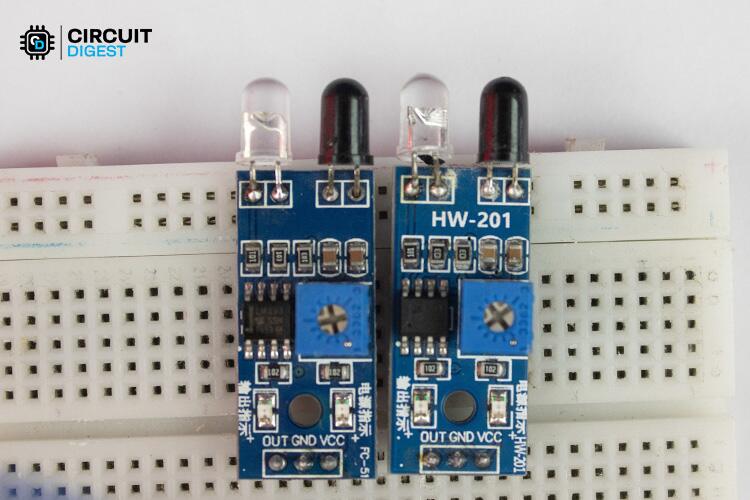
By placing two IR sensors one after another in series as shown in the above image at a single entry/exit point, we can track the direction in which a visitor is moving. Here is how we detect the entry and exit of a visitor
Entry Detection - If Sensor 1 detects a person first, followed by Sensor 2 within a specific timeout period, it means the visitor is entering the room.
Exit Detection - If Sensor 2 detects a person first, followed by Sensor 1 within a specific timeout period, it means the visitor is leaving the room.
The timeout period ensures accuracy by preventing errors from partial crossings or accidental triggers. For example, let's consider if only one sensor is triggered and the second sensor does not detect movement within the timeout period, then it completely ignores the detection to avoid a false trigger.
Components Required
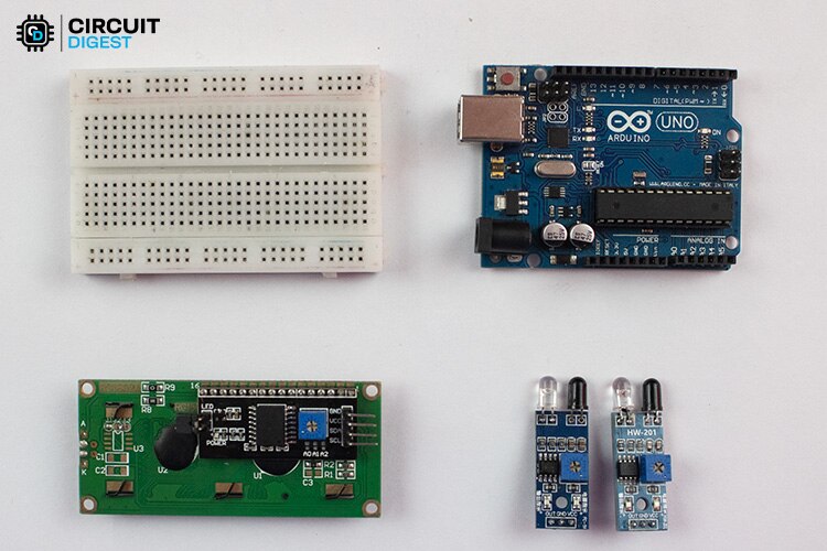
Here is the simple list of components, which is mandatory to build an arduino visitor counter. Let’s see what are the things we need.
A pair of IR Sensors
Breadboard
Connecting wires
12V Barrel Jack Power Adaptor
In the next section, we will be going to see the block diagram of this Bidirectional, which gives an overview of this system’s architecture.
Block Diagram for Bidirectional Visitor Counter
Below you can find the block diagram which describes the Bidirectional Counter System design architecture
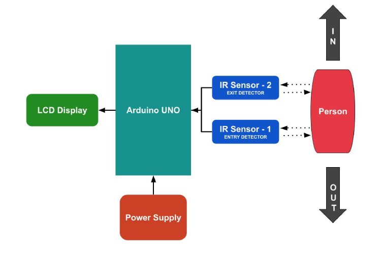
Here you can notice that the pair of IR sensors is used for determining whether the person is entering or leaving, by knowing which sensor gets triggered first, followed by checking whether the consecutive sensor gets triggered within the time frame as we discussed previously.
Later the count details get updated on the LCD display, Here Arduino gets powered by an external power source, and later connected components get drawn power from the Arduino power pins.
Circuit Diagram
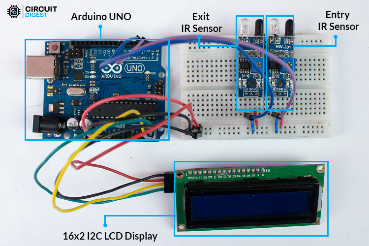
Here you can find the circuit diagram for the Bidirectional Counter using Arduino. The circuit diagram below represents how an Arduino, a pair of IR sensors, and the LCD display are secured together to create a functional system.

For Power supply purposes, I decided to use a 12V DC Power Adaptor to power this whole setup through a barrel jack connector. In the below image, you can find our actual hardware setup of our Bidirectional Counter System using Arduino and IR sensors, by using the above circuit diagram as a reference.
Tips to Avoid False Trigger
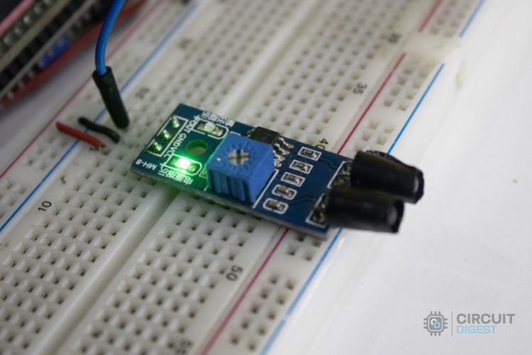
Here is a hardware hack tip, if you need to avoid the false trigger and precisely detect the person’s movement, you want to make sure the pair of IR sensors are placed as near as possible as shown in the above pic.
You can also wrap your IR LED sensor using black tape by leaving the focus point alone uncovered to avoid getting triggered due to Sunlight or external environmental factors, as shown in the below image.
That’s all about the hardware part, Next we are going to dive into the software part to give life to our hardware. Let’s get started.
Arduino code for Bidirectional Counter System
The complete code for a Bidirectional counter system using Arduino is given below. It continuously checks for which sensor gets triggered first. It then checks whether consecutive sensors get triggered within the timeout period. Based on that it counts the people gone inside and left outside. Later it calculates the Current count of people and makes those values get updated on Display.
//Code for Arduino bidirectional visitor counter
//by www.circuitdigest.com
#include <LiquidCrystal_I2C.h>
// Initialize the LCD with I2C address 0x27
LiquidCrystal_I2C lcd(0x27, 16, 2);
const int irPin1 = 2; // IR sensor 1(Entrance Detector) connected to digital pin 2
const int irPin2 = 3; // IR sensor 2(Exit Detector) connected to digital pin 3
int in_count = 0;        // Variable to store the number of people went inside
int out_count = 0;       // Variable to store the number of people went outside
int current_count = 0;   // Variable to store the current number of people present inside
const unsigned long timeout = 50; // Object detection Timeout period in milliseconds
void setup() {
 /* Initialise LCD Display */
 lcd.init();
 lcd.backlight();
 lcd.setCursor(0, 0);
 lcd.print("IN: 0   OUT: 0");
 lcd.setCursor(0, 1);
 lcd.print("Current: 0");
 /* Pull up the input pins */
 pinMode(irPin1, INPUT_PULLUP);
 pinMode(irPin2, INPUT_PULLUP);
}
void loop() {
 /*  Check if the first sensor is triggered */
 if (digitalRead(irPin1) == LOW) {
   unsigned long startTime = millis();
   while ((millis() - startTime) < timeout) {
     if(digitalRead(irPin2) == LOW){
        ++in_count;
        updateDisplay();
        break;
     }
   }
   //wait until both sensors return to a normal state
   while(!digitalRead(irPin1) || !digitalRead(irPin2));
 }

 /* Check if the second sensor is triggered */
 else if (digitalRead(irPin2) == LOW) {
   unsigned long startTime = millis();
   while ((millis() - startTime) < timeout) {
     if(digitalRead(irPin1) == LOW){
       if(out_count < in_count){
          ++out_count;
          updateDisplay();
          break;
       }
     }
   }
   //wait until both sensors return to a normal state
   while(!digitalRead(irPin1) || !digitalRead(irPin2));
 }
}
void updateDisplay() {
 lcd.setCursor(4, 0);
 lcd.print("   ");
 lcd.setCursor(4, 0);
 lcd.print(in_count);
 lcd.setCursor(13, 0);
 lcd.print("   ");
 lcd.setCursor(13, 0);
 lcd.print(out_count);
 current_count = in_count - out_count;
 lcd.setCursor(9, 1);
 lcd.print("   ");
 lcd.setCursor(9, 1);
 lcd.print(current_count);
}
Including HeaderFiles
#include <LiquidCrystal_I2C.h>In order to make our Arduino UNO communicate with a 16x2 I2C LCD display properly, the above library is an essential one. Here you can get this library by clicking here LiquidCrystal_I2C.h.
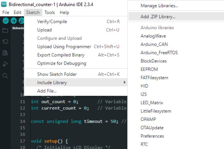
After downloading the ZIP file from the Github Repository, you can install it either through the Arduino IDE, by going to Sketch -> Include Library -> Add ZIP Library and selecting the .ZIP file, or by just simply extracting the Zip file into the Arduino Library folder.
Create an LCD Object
// Initialize the LCD with I2C address 0x27
LiquidCrystal_I2C lcd(0x27, 16, 2);
Here I create an Object of the LiquidCrystal_I2C class by specifying the I2C address used by your LCD display, in my case it is (0x27), followed by specifying the number of columns(16) and number of rows(2).
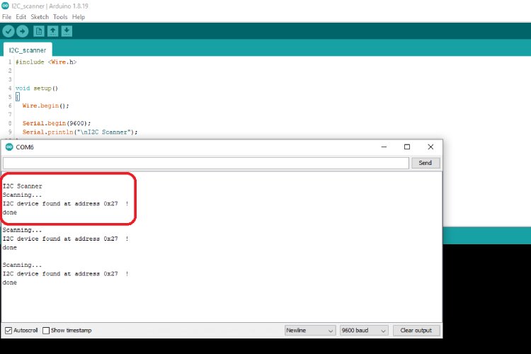
If you don’t know the I2C address of your I2C LCD display, Just copy the code from this GitHub link, and paste it into Arduino IDE to dump the code. Later you got the I2C address of the display in the serial Monitor.
Global Variable Declaration
const int irPin1 = 2; // IR sensor 1(Entrance Detector) connected to digital pin 2
const int irPin2 = 3; // IR sensor 2(Exit Detector) connected to digital pin 3
Here I declare the variables for the Arduino Pins which get connected to the IR sensor signal pins. Here Digital pin 2 is connected to the IR sensor 1 signal pin and Digital pin 3 is connected to the IR sensor 2 signal pin.
int in_count = 0;        // Variable to store the number of people went inside
int out_count = 0;       // Variable to store the number of people went outside
int current_count = 0;   // Variable to store the current number of people present inside
These above variables are used for storing the count of the number of people gets entered, the number of people moveing outside, and the current number of people present inside.
const unsigned long timeout = 50; // Object detection Timeout period in millisecondsThe timeout variable is used to set the minimum time required for the following IR sensor to get triggered after the trigger of the first IR sensor. Here I set 50ms due to the shorter distance between the two IR sensors.
updateDisplay() Function to Update the count on Display
void updateDisplay() {
 lcd.setCursor(4, 0);
 lcd.print("   ");
 lcd.setCursor(4, 0);
 lcd.print(in_count);
 lcd.setCursor(13, 0);
 lcd.print("   ");
 lcd.setCursor(13, 0);
 lcd.print(out_count);
 current_count = in_count - out_count;
 lcd.setCursor(9, 1);
 lcd.print("   ");
 lcd.setCursor(9, 1);
 lcd.print(current_count);
}
This function is used to update the count of a number of people who come inside, the number of people gone outside, and the current number of people present inside that is shown on the I2C LCD display.
Setup() Function to Initialize GPIO Pins and Display
void setup() {
 /* Initialise LCD Display */
 lcd.init();
 lcd.backlight();
 lcd.setCursor(0, 0);
 lcd.print("IN: 0   OUT: 0");
 lcd.setCursor(0, 1);
 lcd.print("Current: 0");
 /* Pull up the input pins */
 pinMode(irPin1, INPUT_PULLUP);
 pinMode(irPin2, INPUT_PULLUP);
}
This setup() function is used to initialize the 16x2 I2C LCD display by setting the backlight and bring back the default values on it. After that make the Digital pins 2 and 3 as Digital input pins with internal pull-ups to avoid noise due to floating signal pins.
Loop() Function to continuously check for Sensor Trigger
void loop() {
 /*  Check if the first sensor is triggered */
 if (digitalRead(irPin1) == LOW) {
   unsigned long startTime = millis();
   while ((millis() - startTime) < timeout) {
     if(digitalRead(irPin2) == LOW){
        ++in_count;
        updateDisplay();
        break;
     }
   }
   //wait until both sensors return to a normal state
   while(!digitalRead(irPin1) || !digitalRead(irPin2));
 }

 /* Check if the second sensor is triggered */
 else if (digitalRead(irPin2) == LOW) {
   unsigned long startTime = millis();
   while ((millis() - startTime) < timeout) {
     if(digitalRead(irPin1) == LOW){
       if(out_count < in_count){
          ++out_count;
          updateDisplay();
          break;
       }
     }
   }
   //wait until both sensors return to a normal state
   while(!digitalRead(irPin1) || !digitalRead(irPin2));
 }
}
This loop() keeps on checking for, which sensor gets triggered first, suppose if the second sensor gets triggered(Exit Sensor), it jumps on the else if statement and starts the countdown using millis().
After that, it continuously checks for whether the following IR sensor (In this case, it is the First IR Sensor [Entry Sensor]) is getting triggered or not within the set timeout(50 ms). If it detects within timeout, it makes a count on it and updates it on display. If not, it just discards this whole trigger status.
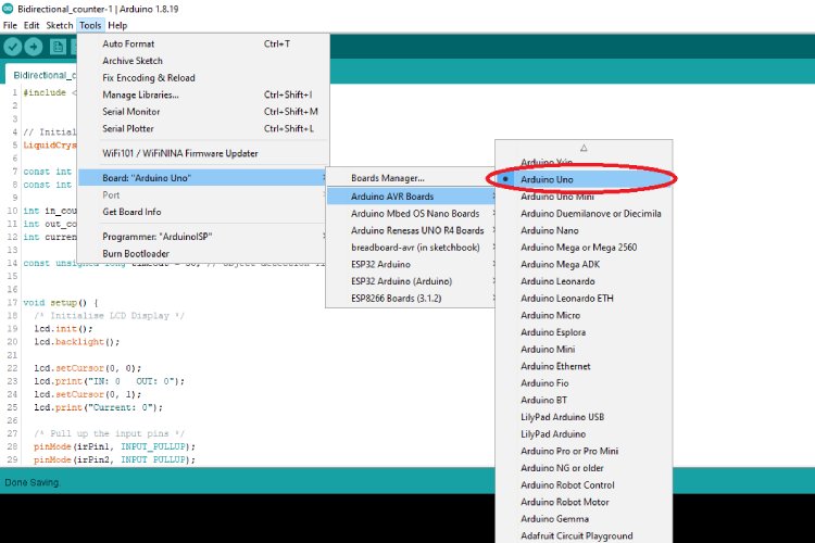
Uploading Code to Arduino UNO
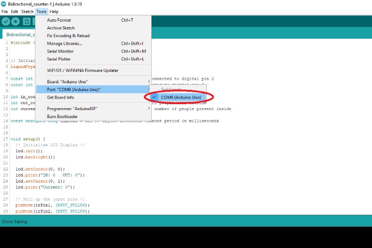
It is the stage where we are going to give life to the Arduino UNO board. For that, let's make sure the board is properly selected in the Arduino IDE.
After that, we want to select the USB Serial port associated with our Arduino UNO Board.
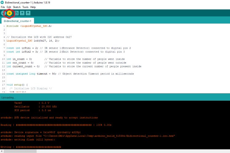
Finally, click the upload button in order to bring back the new life to our Arduino.
Demo of Bidirectional Counter System using Arduino
This is the most exciting phase, yeah, it is time to experiment with our Innovation. If everything goes right, you will be able to see the actual working as shown in the GIF below.
This arduino bidirectional counter, not only displays the current number of people or objects present inside, but it also tracks and displays the history of how many members entered inside and left outside.
Arduino Bidirectional Visitor Counter - Working Video
The above video shows step by step instructions on how to build a bidirectional visitor counter project using Arduino. If you have any questions please feel free to ask them in the comment section below or use our forums.
GitHub Repo with Code and Circuit
The complete code for Bidirectional Counter System using IR Sensors project is given at the bottom of this page. Further more here is also a link to our GitHub repo, where you'll find the source code for this project.

Similar Projects
These projects showcase how IR sensors can be used for automation and monitoring, including visitor counting, object tracking, and speed measurement. Each project provides a hands-on learning experience in sensor integration and embedded system development using Arduino.

Automatic Room Light Controller with Bidirectional Visitor Counter
This project employs an Arduino Uno along with IR sensors to count the number of people entering or exiting a room. It automatically controls the room's lighting based on occupancy, ensuring lights are turned on when someone enters and off when the room is vacant.

Arduino Currency Counter using IR and Color Sensor
Arduino Uno is combined with IR and TCS230 color sensors to detect and count paper currency notes. The system identifies different denominations and displays the total amount on a 16x2 LCD.

DIY Tachometer using Arduino and IR Sensor
Demonstrates how to build a digital tachometer using an Arduino and an IR sensor module. It measures the rotations per minute (RPM) of a rotating object by detecting interruptions in the IR beam, providing accurate speed readings.

Coin Sorting Machine using Arduino
Learn how to build a coin sorting and counting machine built with Arduino. It utilizes IR sensors to detect and count coins of different denominations as they pass through designated paths, displaying the count on an LCD.

Crowd Monitoring Device with Arduino UNO R4 and IoT Cloud
This project integrates Arduino Cloud to enable remote monitoring of crowd density. An IR sensor detects individuals entering or exiting a premises, and the data is transmitted to the IoT dashboard for real-time monitoring.
Complete Project Code
#include <LiquidCrystal_I2C.h>

// Initialize the LCD with I2C address 0x27
LiquidCrystal_I2C lcd(0x27, 16, 2);
const int irPin1 = 2; // IR sensor 1(Entrance Detector) connected to digital pin 2
const int irPin2 = 3; // IR sensor 2(Exit Detector) connected to digital pin 3
int in_count = 0;        // Variable to store the number of people went inside
int out_count = 0;       // Variable to store the number of people went outside
int current_count = 0;   // Variable to store the current number of people present inside
const unsigned long timeout = 50; // Object detection Timeout period in milliseconds

void setup() {
 /* Initialise LCD Display */
 lcd.init();
 lcd.backlight();
 lcd.setCursor(0, 0);
 lcd.print("IN: 0   OUT: 0");
 lcd.setCursor(0, 1);
 lcd.print("Current: 0");

 /* Pull up the input pins */
 pinMode(irPin1, INPUT_PULLUP);
 pinMode(irPin2, INPUT_PULLUP);
}

void loop() {
 /*  Check if the first sensor is triggered */
 if (digitalRead(irPin1) == LOW) {
   unsigned long startTime = millis();
   while ((millis() - startTime) < timeout) {
     if(digitalRead(irPin2) == LOW){
        ++in_count;
        updateDisplay();
        break;
     }
   }
   //wait until both sensors return to a normal state
   while(!digitalRead(irPin1) || !digitalRead(irPin2));
 }

 /* Check if the second sensor is triggered */
 else if (digitalRead(irPin2) == LOW) {
   unsigned long startTime = millis();
   while ((millis() - startTime) < timeout) {
     if(digitalRead(irPin1) == LOW){
       if(out_count < in_count){
          ++out_count;
          updateDisplay();
          break;
       }
     }
   }
   //wait until both sensors return to a normal state
   while(!digitalRead(irPin1) || !digitalRead(irPin2));
 }

}

void updateDisplay() {
 lcd.setCursor(4, 0);
 lcd.print("   ");
 lcd.setCursor(4, 0);
 lcd.print(in_count);
 lcd.setCursor(13, 0);
 lcd.print("   ");
 lcd.setCursor(13, 0);
 lcd.print(out_count);
 current_count = in_count - out_count;
 lcd.setCursor(9, 1);
 lcd.print("   ");
 lcd.setCursor(9, 1);
 lcd.print(current_count);
}
