
Pulse Width Modulation (PWM) is a technique that varies the width of a pulse while keeping the wave frequency constant. The PWM technique mainly used to control the brightness of the LED, speed of DC motor, controlling a servo motor, or in other cases, where have to generate an analog signal using a digital source. We explained the PWM in detail in the previous article.
In this tutorial, we are going to talk about PWM (pulse width modulation) pins of the ESP32 development board. All GPIO pins of ESP32 development board (Except Power, GND, Tx, Rx, and EN) can be used to get the PWM signal. As an ESP32 PWM example, we’ll build a simple circuit that changes the LED brightness according to PWM signals.
Components Required
- ESP32
- LED
- 330 Ω Resistor
- 10k Pot
- Breadboard
PWM Generation
Before explaining the PWM generation on ESP32, let’s discuss some terms associated with PWM.
TON (On Time): The duration of time when the signal is high.
TOFF (Off Time): The duration of time when the signal is low.
Period: It is the sum of on time and off time of the PWM signal.
TotalPeriod = TON + TOFF
Duty Cycle: The percentage of time when the signal was high during the period of the PWM signal.
Duty Cycle = TON /TTotal * 100
For example, if a pulse with a total period of 10ms remains ON (high) for 5ms. Then, the duty cycle will be:
Duty Cycle = 5/10 * 100 = 50% Duty Cycle
Frequency of a PWM: The frequency of a PWM signal determines how fast a PWM completes one period. One Period is complete ON and OFF of a PWM signal as shown in the above figure.
We also created PWM tutorials with many other popular Microcontrollers like Arduino, Raspberry Pi, MSP430 etc:
- Raspberry Pi PWM Tutorial
- Arduino Based LED Dimmer using PWM
- Pulse width Modulation (PWM) using MSP430G2
- ARM7-LPC2148 PWM Tutorial: Controlling Brightness of LED
- Pulse width Modulation (PWM) using MSP430G2: Controlling Brightness of LED
- Generating PWM using PIC Microcontroller with MPLAB and XC8
- Pulse width Modulation (PWM) in STM32F103C8: Controlling Speed of DC Fan
Check all the PWM related projects here.
PWM Generation on ESP32
In Arduino and NodeMCU, we use the analogWrite() function to "write" value between 0 and 254 to the LED pin. But the ESP32 development board does not support the analogWrite() function. So instead of analogWrite(), we will use another function i.e. the ledcWrite() function. The ledcWrite() is very similar to analogWrite(). It also requires two parameters: The PWM channel that we want to "write" a PWM value to and the PWM value which we want to write to the selected channel. ESP32 has 16 PWM channels, and you can use any GPIO to generate PWM output. The ESP32 provides three functions to assign a PWM channel to a pin and to configure the resolution, frequency, and duty cycle of PWM signals. These functions are:
ledcAttachPin(gpio, channel)
ledcSetup(channel, frequency, resolution)
ledcWrite(channel, dutycycle)
Circuit Diagram
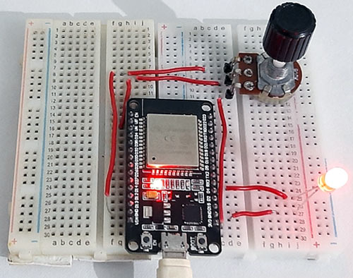
The circuit diagram for ESP32 PWM is given below.

The circuit contains a single LED, a resistor, and a 10K potentiometer. The negative pin of LED is connected to the GND of ESP32 through a 330 Ω resistor. You can use any resistor value between 230 Ω and 500 Ω. Connect the LED positive pin to GPIO 16 and signal pin of Pot to ADC1 (VP) pin of ESP32.
Code Explanation for ESP32 PWM
The complete code is given at the end of the page.
This code doesn’t require any library, so start your code by defining the pin, the LED is attached to. In my case, I used GPIO 16 to connect the LED.
const int ledPin = 16; // 16 corresponds to GPIO16
After that, set the PWM signal properties in the next lines. I set the PWM frequency to 9000, and the resolution to 10, you can change it to generate different PWM signals. ESP32 boards support PWM resolution from 1 bit to 16 bits. You also need to choose a PWM channel. ESP32 has a total of 16 (0 to 15) PWM channels.
const int freq = 9000;
const int ledChannel = 0;
const int resolution = 10;
Now inside the void setup() function, configure the LED PWM with the properties you set earlier by using the ledcSetup() function. In the next line, define the GPIO pin where the LED is connected. The ledcAttachPin() function is used to define the GPIO pin and the channel that is generating the signal. In my case, I used the ledPin that is GPIO 16 and ledChannel that corresponds to channel 0.
void setup(){
  Serial.begin(9600);
  ledcSetup(ledChannel, freq, resolution);
  ledcAttachPin(ledPin, ledChannel);
}
In the void loop, read the Analog pin where the Pot is connected and store the reading in a variable called ‘dutyCycle’. The LED brightness will increase or decrease according to the rotation of potentiometer. The ledcWrite() is very similar to analogWrite().
void loop(){
   dutyCycle =  analogRead(A0);
   ledcWrite(ledChannel, dutyCycle);
   delay(15);
  }
Testing the ESP32 PWM Signals
To test the ESP32 PWM signals, connect the LED and potentiometer as per the circuit diagram, and upload the code to your ESP32. Make sure you have the right board and COM port selected. Now rotate the potentiometer to increase or decrease the LED brightness.
Complete working is shown in the video given below. Also, check other ESP32 based projects by following the link.
Complete Project Code
const int ledPin = 16;  // 16 corresponds to GPIO16
uint16_t dutyCycle;
// setting PWM properties
const int freq = 15000;
const int ledChannel = 0;
const int resolution = 13;
void setup(){
  Serial.begin(9600);
  // configure LED PWM functionalitites
  ledcSetup(ledChannel, freq, resolution);
  // attach the channel to the GPIO to be controlled
  ledcAttachPin(ledPin, ledChannel);
}
void loop(){
   dutyCycle =  analogRead(A0);
   Serial.print(dutyCycle);
   // changing the LED brightness with PWM
   ledcWrite(ledChannel, dutyCycle);
   delay(15);
  }
This doesn't work on a Heltec ESP32 WiFi Kit. Use the onboard PWMExample sketch instead.
ESP32PWM::allocateTimer(0);
pwm.attachPin(APin, freq,10); //1KHz 8 bit
void loop() {
pwm.writeScaled(brightness);
delay(2);