 Vedhathiri
Author

Nowadays, everything is rapidly transitioning into the digital world, from the way we communicate to how industries operate and services are delivered. Traditional methods that once relied on manual processes are now being replaced by smart, automated, and interconnected systems. Building an automated attendance system using ESP32-CAM is a practical, affordable way to solve this problem for classrooms, coaching centres, hostels, and small offices.
Think about your daily life. You no longer need to stand in long queues to pay bills; you can do it instantly with just a few taps on your phone. Carrying cash is becoming optional, as digital payments are fast, secure, and widely accepted. Even documents have gone digital; you can store, share, and access them anytime, anywhere without worrying about losing paper copies. So, in a world that is becoming smarter and faster, why should attendance systems remain outdated? Every day in classrooms, time is spent calling out names, “Arun?” “Present, ma’am.” “Geetha?” “Absent, ma’am.” This process is repetitive, time-consuming, and prone to errors. It takes away valuable teaching time and often leads to manual mistakes in recording or maintaining records. This tutorial provides a complete, hands-on walkthrough of the ESP32-CAM based attendance system: from understanding the hardware and circuit diagram, to explaining every block of the source code, to troubleshooting common issues
Table of Contents
What You Will Build: System Overview
The ESP32-CAM attendance system is a self-contained IoT device fixed at a classroom entrance. So, the question is, in a world that is becoming smarter and faster, why should attendance systems remain the same? This idea led to the development of a smarter solution: an automated attendance system using ESP32-CAM. It simplifies the process by recording attendance instantly with time and image proof, making it efficient, reliable, and error-free. To get started, we suggest you explore our tutorial, How to Send WhatsApp Messages from ESP32, which offers a clear and structured walkthrough.
| Feature | Manual Register | RFID-Based | ESP32-CAM Based |
| Photo verification | No | No | captured on each event |
| Real-time parent/admin alert | No | Limited | WhatsApp with image |
| Accurate timestamp | Manual/prone to error | System clock | NTP-synchronised |
| Cost (approx. INR) | Nil | ₹500–₹1,500 | ₹600–₹900 |
| Internet required | No | No | Yes (Wi-Fi) |
| Proxy-attendance prevention | No | No | photo proof |
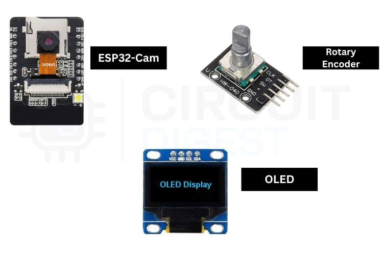
Components Required
The table below lists every component needed to complete the full hardware setup for the attendance system using ESP32-CAM.
| S.No | Components | Purpose |
| 1. | ESP32-Cam | Act as a microcontroller and is also used to capture images |
| 2. | Rotary Encoder | Used to select and also click the option |
| 3. | OLED | For displaying the output of the system |
| 4. | Puff Board | Used to connect all the components easily |
| 5. | Case | Used to give protection and a good look |
Important: If you are using the standard ESP32-CAM (without onboard USB), you will need a USB-to-Serial (FTDI) adapter for programming. Connect FTDI TX → ESP32-CAM RX (U0R), RX → TX (U0T), GND → GND, and hold GPIO0 LOW during upload to enter flash mode. If your board has a micro-USB port already, no adapter is required. If you are just getting started with the ESP32-CAM module, we recommend checking out our guide “How to Program the ESP32-CAM?
Circuit Diagram of the ESP32-CAM Attendance System
The circuit diagram of this system represents the interconnection between the ESP32-CAM, OLED display, and rotary encoder. The OLED is connected to the 13th and 14th pins of the ESP32-Cam, and the rotary encoder is connected to the 15th,2nd, and 4th GPIO pins of the ESP32-Cam.

| Peripheral | Peripheral Pin | ESP32-CAM GPIO |
| OLED Display | SDA | GPIO13 |
| OLED Display | SCL | GPIO14 |
| OLED Display | VCC / GND | 3.3 V / GND |
| Rotary Encoder | CLK | GPIO15 |
| Rotary Encoder | DT | GPIO2 |
| Rotary Encoder | SW (push-button) | GPIO4 |
| Rotary Encoder | VCC / GND | 3.3 V / GND |
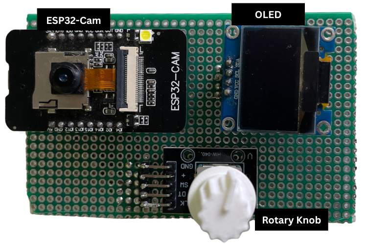
Hardware Setup for the Attendance System Using ESP32-Cam
The hardware connection shows how all components are connected in real time, making the system simple, organized, and efficient for setting up a smart attendance system.
Detailed Working of the ESP32-Cam Attendance System
The working principle of the ESP32-CAM attendance system is simple, but it combines multiple embedded and IoT concepts to make the process smart and efficient. At the core of the system is the ESP32-CAM, which acts as both the microcontroller and the image-capturing device. Once all the hardware connections are completed, the ESP32-CAM, OLED display, rotary encoder, and power supply are all fixed, and the system is mounted in a fixed location, such as at the classroom entrance. When the system is powered through the USB port, the ESP32-CAM initializes and attempts to connect to a predefined Wi-Fi network. This step is crucial because the system relies on internet connectivity for time synchronization and sending data. Once connected successfully, the device fetches the current time from an NTP (Network Time Protocol) server, ensuring accurate and real-time timestamps. After initialisation, the OLED display shows the list of student names that are already stored in the program memory. Now the system becomes interactive.
A student approaches the device and uses the rotary encoder:
- Rotating the encoder scrolls through the list of names.
- Pressing (clicking) the encoder selects the highlighted name.
Once the name is selected, the system prompts the user to choose the event type: “IN” or “OUT.”
Again, the rotary encoder is used:
- Rotate to switch between IN and OUT
- Click to confirm the selection
After confirmation, the system starts a short countdown: 3, 2, 1 displayed on the OLED. This gives the student a moment to position themselves properly in front of the camera. At the end of the countdown, the ESP32-CAM activates and captures an image of the student. Immediately after capturing the image, the system processes the data. The image is combined with details such as student name, event type (IN/OUT), timestamp (from NTP), and location (predefined in code). This data is then sent over the internet using an API (such as the CircuitDigest Cloud API). Within seconds, the registered WhatsApp number receives a message containing:
- The captured image
- Student name
- Entry/Exit status
- Exact time and location
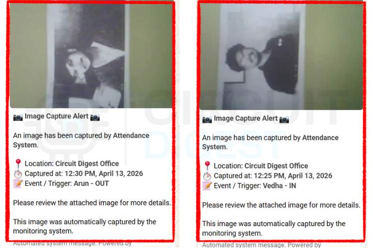
This entire process ensures that every attendance record is verified with visual proof, making the system more reliable than traditional methods. The same workflow is repeated for both “IN” and “OUT” events, allowing complete tracking of student entry and exit. By combining hardware interaction, real-time networking, and cloud communication, this system transforms a basic attendance task into a smart, automated, and secure solution. If you need a different version of the project, we have also done that: an RFID-Based Attendance System Using Arduino. Refer to the link to get full details about it.
Source Code Explanation
The program is designed for the ESP32-CAM and integrates multiple functionalities like camera control, Wi-Fi communication, OLED display, and user input handling. It starts by initializing all required libraries, hardware pins, and system variables. The setup() function configures the camera, connects to Wi-Fi, and prepares the display and input devices. The loop() function continuously reads the rotary encoder input, updates the display, and controls the system flow. Separate functions are used for image capture, data processing, and secure data transmission.
1. Credentials and Configuration
const char *ssid = "YOURSSID";
const char *pwd = "YOURWIFIPASSWORD”;
const char *apiKey = "YOURAPIKEY";
const char *phone = “YOURNUMBER";
This section stores all the required credentials for network and cloud communication. The Wi-Fi SSID and password are used to connect the ESP32-CAM to the internet. The API key and phone number are used to authenticate and send attendance data to WhatsApp via the cloud service.
2. Camera Initialisation
cfg.pixel_format = PIXFORMAT_JPEG;
cfg.frame_size = FRAMESIZE_QVGA;
cfg.jpeg_quality = 12;
cfg.fb_count = 1;
if (esp_camera_init(&cfg) != ESP_OK) {
ESP.restart();
}
This section configures and initializes the ESP32-CAM. The image format is set to JPEG and resolution to QVGA to ensure stable performance with limited memory. If the camera fails to initialize, the system automatically restarts to recover from the error.
3. Rotary Encoder Driver
int clkState = digitalRead(CLK);
if (clkState == LOW && lastCLK == HIGH) {
lastCLK = clkState;
return (digitalRead(DT) != clkState) ? 1 : -1;
}
This code reads the rotary encoder input and determines the direction of rotation. Based on the signal change, it returns +1 or -1, which helps in navigating through menu options. It provides a simple and efficient way for user interaction.
4. Student Name Array
String users[] = {"Vedha", "Arun", "Priya", "Kiran"};
int totalUsers = 4;
int selectedIndex = 0;
This section defines the list of students stored inside the system. The selectedIndex variable keeps track of the currently selected user. This list is displayed on the OLED, allowing users to scroll and select their name.
5. WhatsApp API POST Request
client.println("POST /api/v1/whatsapp/send-with-image HTTP/1.1");
client.println("Host: www.circuitdigest.cloud");
client.print(body);
client.write(imgBuf, imgLen);
This section handles sending the captured image and attendance details to the cloud server. The data is sent using an HTTP POST request in multipart format. Once processed, the server forwards the attendance information to the registered WhatsApp number.
Future Enhancements
The current ESP32-CAM based attendance system is intentionally kept simple to serve as a clear learning platform.
- Face Recognition Integration
- AI-based face recognition can be added to automatically identify students, eliminating manual name selection and improving speed.
- Cloud Database Storage
Attendance data can be stored in a cloud database for secure backup, easy access, and detailed analysis over time. - Mobile App Support
A mobile application can provide real-time notifications, attendance tracking, and remote monitoring for users or administrators. - GPS Location Tracking
Integrating GPS can help record the exact location of attendance, making the system more reliable and location-aware. - Fingerprint/RFID Support
Biometric or RFID authentication can be added for enhanced security and to support multi-factor attendance verification.
Applications of the ESP32-CAM Attendance System
1. Offices and Companies
Can be used for employee attendance with real-time updates, reducing manual tracking and improving efficiency.
2. Coaching Centers
Useful for managing student attendance efficiently while maintaining digital records for reference.
3. Events and Conferences
Enables quick and reliable participant check-in with digital logging and verification.
4. Hostels and Secure Areas
Helps monitor entry and exit of individuals with image proof, improving safety and accountability.
5. Libraries and Study Centers
Helps track student usage, entry time, and duration of stay in a digital format.
6. Examination Halls
Ensures accurate attendance of students during exams with image proof to avoid malpractice.
Troubleshooting
Issue 1: Wi-Fi Connection Failure
If the ESP32-CAM fails to connect to Wi-Fi, check whether the SSID and password are entered correctly in the code. Ensure the network is available and within range. Restart the device and verify that the router is not blocking new connections.
Issue 2: Camera Initialization Failed
If the camera does not initialize, it may be due to incorrect pin configuration or insufficient power supply. Ensure all camera pins are properly defined, and the ESP32-CAM is powered with a stable 5V source. Restarting the device can also resolve temporary issues.
Issue 3: OLED Display Not Working
If the OLED does not display anything, check the I2C connections (SDA, SCL) and verify the correct I2C address (0x3C or 0x3D). Also, ensure proper wiring and power supply. Reinitialising the display in code can help fix communication errors.
Issue 4: Image Not Sending to WhatsApp
If the image is not sent, check the internet connection and API key validity. Ensure the server is reachable and the correct endpoint is used. Also, verify that the image size is within limits and that the request format is correct.
Issue 5: Rotary Encoder Not Responding Properly
If the encoder skips or behaves inconsistently, it may be due to noise or improper connections. Ensure proper wiring and use debouncing logic in code. Adding small delays or checking timing conditions can improve accuracy.
Conclusion
In conclusion, this ESP32-CAM attendance system project shows how a simple idea can be improved using modern technology to make it faster, smarter, and more reliable. Instead of depending on manual work, the system uses automation to reduce time, effort, and human errors. It also ensures that the data is recorded accurately and can be accessed easily whenever needed. Overall, this work gives a clear understanding of how embedded systems and IoT can be used in real-life applications. It also creates a strong base for developing more advanced and intelligent systems in the future. This ESP32-CAM attendance system tutorial demonstrates how an IoT device can replace a process that has barely changed in a century. We have also done an interesting project, a Biometric Attendance System with Google Sheets Integration, which provides a clear understanding of how biometric systems work and how to handle and manage data using Google Sheets effectively. So, explore our collection to discover more ESP32-based project ideas.
Frequently Asked Questions
1. Can the ESP32-CAM attendance system work without the internet?
No, an internet connection is required for time synchronization and sending attendance data.
2. How does the system ensure accurate time for attendance?
The system uses NTP (Network Time Protocol) to fetch real-time data from the internet, ensuring accurate timestamps.
3. What is the role of the rotary encoder in this attendance project?
The rotary encoder is used for user interaction, allowing selection of names and options like IN or OUT.
4. How is the attendance data sent to the user?
The data, along with the captured image, is sent through a cloud API to a registered WhatsApp number.
5. What happens if the Wi-Fi connection is lost?
The system attempts to reconnect automatically, and if it fails, it may restart to restore proper functionality.
6. Can more students be added to the ESP32-CAM attendance system?
Yes, more students can be added by updating the user list in the program code.
7. Is the system secure?
Basic security is provided through API authentication, but it can be further enhanced with encryption or user authentication methods.
8. What is the resolution of the attendance photo taken with the ESP32-CAM (firmware)?
For attendance photography, the firmware is configured for QVGA (320 × 240 pixels) at a JPEG quality setting of 12. Typically, this will create files between 15 and 40 KB in size. These files will be of good enough quality to capture an image of someone's face, yet small enough to transfer quickly over most Wi-Fi connections. If you are concerned with the quality of the image, you can change the configuration to VGA (640 × 480 pixels) at JPEG quality 10, and if you have sufficient bandwidth, you will receive a clearer image than if you were using QVGA and JPEG quality setting 12.
9. Do I need an FTDI Adapter for the ESP32-CAM?
You will need an FTDI adapter if you are using one of the standard AI-Thinker ESP32-CAM boards that do not have USB ports. To connect these boards to the FTDI adapter, connect the FTDI TX line to the ESP32-CAM RX (U0R) line, the FTDI RX line to the ESP32-CAM TX (U0T) line, and the Ground (GND) wire from the FTDI adapter to the Ground (GND) wire on the ESP32-CAM board. You should hold the GPIO0 pin low while you are uploading the code using the Arduino IDE. After the upload has completed, you can release your GPIO0 pin and press the reset button. You will not need an FTDI adapter if you are using the ESP32-CAM-MB programmer board
GitHub Repository
If you want the project code, check out this GitHub repository.


Relevant Projects Using CircuitDigest Cloud
These projects show how ESP32, Arduino, and Raspberry Pi Pico can send real-time WhatsApp alerts using WiFi and cloud APIs, enabling smart monitoring and automation without GSM modules.

Raspberry Pi Pico-Based Rain Detection System with WhatsApp Alert
A Raspberry Pi Pico W-based rain detection system that sends real-time WhatsApp alerts via WiFi using CircuitDigest Cloud without GSM hardware.

How to Send WhatsApp Messages from Arduino Uno R4 Wifi Board
Send WhatsApp alerts from Arduino using WiFi and CircuitDigest Cloud API, where sensor data triggers messages without GSM or complex setup.

Real-Time Motion Detection with XIAO ESP32 WhatsApp Alert System
Real-time motion detection system using XIAO ESP32 and an IR sensor that sends instant WhatsApp alerts via WiFi using CircuitDigest Cloud—no GSM required.
Complete Project Code
#include "esp_camera.h"
#include "esp_task_wdt.h" // Watchdog
#include <Adafruit_GFX.h>
#include <Adafruit_SSD1306.h>
#include <WiFi.h>
#include <WiFiClientSecure.h>
#include <Wire.h>
#include <time.h>
// ---------------- OLED ----------------
#define SCREEN_WIDTH 128
#define SCREEN_HEIGHT 64
Adafruit_SSD1306 display(SCREEN_WIDTH, SCREEN_HEIGHT, &Wire, -1);
// ---------------- WiFi ----------------
const char *ssid = "Wifi SSID";
const char *pwd = "Wifi Password";
const char *apiKey = "YourApikey";
const char *phone = "Yourphonenumber";
// ---------------- Encoder ----------------
#define CLK 15
#define DT 3
#define SW 2
// ---------------- Users ----------------
String users[] = {"Vedha", "Arun", "Priya", "Kiran"};
int totalUsers = 4;
int selectedIndex = 0;
// ---------------- Mode ----------------
int modeIndex = 0;
String modeOptions[] = {"IN", "OUT"};
// ---------------- State ----------------
bool selectingMode = false;
unsigned long bootTime;
int lastCLK = HIGH;
bool lastSW = HIGH;
unsigned long lastEncoderMove = 0;
unsigned long lastSWPress = 0;
// ---------------- Camera Init ----------------
void initCam() {
 camera_config_t cfg;
 cfg.ledc_channel = LEDC_CHANNEL_0;
 cfg.ledc_timer = LEDC_TIMER_0;
 cfg.pin_d0 = 5;
 cfg.pin_d1 = 18;
 cfg.pin_d2 = 19;
 cfg.pin_d3 = 21;
 cfg.pin_d4 = 36;
 cfg.pin_d5 = 39;
 cfg.pin_d6 = 34;
 cfg.pin_d7 = 35;
 cfg.pin_xclk = 0;
 cfg.pin_pclk = 22;
 cfg.pin_vsync = 25;
 cfg.pin_href = 23;
 cfg.pin_sscb_sda = 26;
 cfg.pin_sscb_scl = 27;
 cfg.pin_pwdn = 32;
 cfg.pin_reset = -1;
 cfg.xclk_freq_hz = 20000000;
 cfg.pixel_format = PIXFORMAT_JPEG;
 cfg.frame_size = FRAMESIZE_QVGA; // Keep QVGA — smaller = more stable
 cfg.jpeg_quality = 12;
 cfg.fb_count = 1; // Single buffer — safer with OLED
 if (esp_camera_init(&cfg) != ESP_OK) {
   Serial.println("Camera Init Failed");
   ESP.restart();
 }
}
// ---------------- OLED Init ----------------
void initOLED() {
 Wire.begin(14, 13);
 Wire.setClock(100000);
 delay(100);
 if (!display.begin(SSD1306_SWITCHCAPVCC, 0x3C)) {
   if (!display.begin(SSD1306_SWITCHCAPVCC, 0x3D)) {
     Serial.println("OLED FAIL");
     while (true)
       ;
   }
 }
 display.clearDisplay();
 display.setTextColor(WHITE);
 display.display();
}
// ---------------- OLED Screens ----------------
void showWelcome() {
 display.clearDisplay();
 display.setTextSize(2);
 display.setCursor(5, 20);
 display.println("Attendance");
 display.display();
 delay(2000);
}
void showUsers() {
 display.clearDisplay();
 display.setTextSize(2); // Bigger text
 // At size 2: each row is ~16px tall; fit 3 rows with 21px spacing on 64px
 // screen
 int rowH = 21;
 int visible = 3;
 int startIdx = selectedIndex - 1;
 if (startIdx < 0)
   startIdx = 0;
 if (startIdx > totalUsers - visible)
   startIdx = max(0, totalUsers - visible);
 for (int i = startIdx; i < min(startIdx + visible, totalUsers); i++) {
   int y = (i - startIdx) * rowH;
   if (i == selectedIndex) {
     display.fillRect(0, y, SCREEN_WIDTH, rowH, WHITE);
     display.setTextColor(BLACK);
   } else {
     display.setTextColor(WHITE);
   }
   display.setCursor(4, y + 2);
   display.println(users[i]);
 }
 display.setTextColor(WHITE);
 display.display();
}
void showMode() {
 display.clearDisplay();
 // Header: name in size 1 to save space, then a divider
 display.setTextSize(1);
 display.setTextColor(WHITE);
 display.setCursor(0, 0);
 display.println(users[selectedIndex]);
 display.drawLine(0, 10, SCREEN_WIDTH, 10, WHITE);
 // Options in size 2
 display.setTextSize(2);
 if (modeIndex == 0) {
   display.fillRect(0, 14, SCREEN_WIDTH, 22, WHITE);
   display.setTextColor(BLACK);
 } else {
   display.setTextColor(WHITE);
 }
 display.setCursor(4, 16);
 display.println("IN");
 if (modeIndex == 1) {
   display.fillRect(0, 40, SCREEN_WIDTH, 22, WHITE);
   display.setTextColor(BLACK);
 } else {
   display.setTextColor(WHITE);
 }
 display.setCursor(4, 42);
 display.println("OUT");
 display.setTextColor(WHITE);
 display.display();
}
void showMessage(String msg) {
 display.clearDisplay();
 display.setTextSize(2); // Bigger text
 display.setTextColor(WHITE);
 display.setCursor(0, 10);
 display.println(msg);
 display.display();
}
void showCountdown() {
 for (int i = 3; i >= 1; i--) {
   display.clearDisplay();
   display.setTextSize(4);
   display.setTextColor(WHITE);
   display.setCursor(55, 12);
   display.println(i);
   display.display();
   esp_task_wdt_reset(); // Feed watchdog during delay
   delay(1000);
 }
 display.clearDisplay();
 display.setTextSize(2);
 display.setTextColor(WHITE);
 display.setCursor(10, 20);
 display.println("Cheese! :)");
 display.display();
 delay(300);
}
// ---------------- Encoder ----------------
int readEncoderDelta() {
 int clkState = digitalRead(CLK);
 if (clkState == LOW && lastCLK == HIGH) {
   lastCLK = clkState;
   if (millis() - lastEncoderMove < 200)
     return 0;
   lastEncoderMove = millis();
   return (digitalRead(DT) != clkState) ? 1 : -1;
 }
 lastCLK = clkState;
 return 0;
}
bool readSWPress() {
 bool swState = digitalRead(SW);
 if (swState == LOW && lastSW == HIGH) {
   lastSW = swState; // record edge immediately
   if (millis() - lastSWPress > 300) {
     lastSWPress = millis();
     return true;
   }
   return false;
 }
 if (swState == HIGH)
   lastSW = HIGH; // only reset when button is released
 return false;
}
// ---------------- WhatsApp Send ----------------
// ✅ NO camera deinit — pass image buffer directly
void sendWa(uint8_t *imgBuf, size_t imgLen) {
 if (WiFi.status() != WL_CONNECTED) {
   showMessage("Reconnecting\nWiFi...");
   WiFi.reconnect();
   int w = 0;
   while (WiFi.status() != WL_CONNECTED && w < 20) {
     delay(500);
     w++;
     esp_task_wdt_reset();
   }
   if (WiFi.status() != WL_CONNECTED) {
     showMessage("WiFi Lost!\nRestarting...");
     delay(2000);
     ESP.restart();
   }
 }
 WiFiClientSecure client;
 client.setInsecure();
 client.setTimeout(20);
 showMessage("Connecting\nto server...");
 esp_task_wdt_reset();
 if (!client.connect("www.circuitdigest.cloud", 443)) {
   Serial.println("Server Connection Failed");
   showMessage("Server Failed!\nRetry later.");
   delay(2000);
   return;
 }
 esp_task_wdt_reset();
 struct tm ti;
 char ts[64] = "Time Unknown";
 if (getLocalTime(&ti, 1000)) {
   strftime(ts, 64, "%I:%M %p, %B %d, %Y", &ti);
 }
 String name = users[selectedIndex];
 String statusMode = modeOptions[modeIndex];
 String variables = "{\"event_type\":\"" + name + " - " + statusMode +
                    "\","
                    "\"location\":\"Office\","
                    "\"device_name\":\"ESP32 CAM #1\","
                    "\"captured_time\":\"" +
                    String(ts) + "\"}";
 String b = "ESP32CAMBound7MA4YWxkTrZu0gW";
 String cr = "\r\n";
 String d = "--";
 String body =
     d + b + cr + "Content-Disposition: form-data; name=\"phone_number\"" +
     cr + cr + String(phone) + cr + d + b + cr +
     "Content-Disposition: form-data; name=\"template_id\"" + cr + cr +
     "image_capture_alert" + cr + d + b + cr +
     "Content-Disposition: form-data; name=\"variables\"" + cr + cr +
     variables + cr + d + b + cr +
     "Content-Disposition: form-data; name=\"image\"; filename=\"p.jpg\"" +
     cr + "Content-Type: image/jpeg" + cr + cr;
 String endPart = cr + d + b + d + cr;
 int totalLen = body.length() + imgLen + endPart.length();
 client.println("POST /api/v1/whatsapp/send-with-image HTTP/1.1");
 client.println("Host: www.circuitdigest.cloud\r\nAuthorization: " +
                String(apiKey));
 client.println("Content-Type: multipart/form-data; boundary=" + b);
 client.println("Content-Length: " + String(totalLen) + "\r\n");
 esp_task_wdt_reset();
 showMessage("Uploading\nimage...");
 client.print(body);
 client.write(imgBuf, imgLen);
 client.print(endPart);
 esp_task_wdt_reset();
 // Read response
 Serial.println("--- Server Response ---");
 while (client.connected()) {
   esp_task_wdt_reset();
   String line = client.readStringUntil('\n');
   Serial.println(line);
   if (line == "\r")
     break;
 }
 while (client.available()) {
   esp_task_wdt_reset();
   Serial.println(client.readStringUntil('\n'));
 }
 Serial.println("-----------------------");
 client.stop();
 showMessage("Sent!\n" + name + " - " + statusMode);
 delay(2000);
}
// ---------------- Capture ----------------
void captureImage() {
 showCountdown();
 // ✅ Discard first frame (camera auto-exposure needs 1 warm-up frame)
 esp_task_wdt_reset();
 camera_fb_t *warmup = esp_camera_fb_get();
 if (warmup)
   esp_camera_fb_return(warmup);
 // Capture real frame
 camera_fb_t *fb = esp_camera_fb_get();
 if (!fb) {
   showMessage("Capture Failed!\nTry again.");
   delay(2000);
   return;
 }
 // ✅ Copy to heap buffer — do NOT deinit camera
 uint8_t *imgBuf = (uint8_t *)ps_malloc(fb->len); // Use PSRAM if available
 if (!imgBuf) {
   imgBuf = (uint8_t *)malloc(fb->len); // Fallback to normal RAM
 }
 if (!imgBuf) {
   Serial.println("Memory alloc failed!");
   esp_camera_fb_return(fb);
   showMessage("Memory Error!\nTry again.");
   delay(2000);
   return;
 }
 size_t imgLen = fb->len;
 memcpy(imgBuf, fb->buf, imgLen);
 esp_camera_fb_return(fb); // Return frame buffer immediately
 Serial.printf("Image size: %d bytes\n", imgLen);
 sendWa(imgBuf, imgLen);
 free(imgBuf); // Free after send
}
// ---------------- Setup ----------------
void setup() {
 Serial.begin(115200);
 // Force boot-sensitive pins LOW
 pinMode(12, OUTPUT);
 digitalWrite(12, LOW);
 pinMode(15, OUTPUT);
 digitalWrite(15, LOW);
 delay(2000);
 pinMode(4, OUTPUT); // Flash LED — keep OFF always
 digitalWrite(4, LOW);
 pinMode(CLK, INPUT);
 pinMode(DT, INPUT);
 pinMode(SW, INPUT_PULLUP);
 lastCLK = digitalRead(CLK);
 lastSW = digitalRead(SW);
 // ✅ Watchdog set to 30 seconds (IDF v5.x API)
 esp_task_wdt_config_t wdt_cfg = {.timeout_ms = 30000, // 30 seconds
                                  .idle_core_mask = 0,
                                  .trigger_panic = true};
 esp_task_wdt_reconfigure(&wdt_cfg);
 esp_task_wdt_add(NULL);
 initOLED();
 showWelcome();
 initCam();
 showMessage("Connecting WiFi");
 WiFi.begin(ssid, pwd);
 int retries = 0;
 while (WiFi.status() != WL_CONNECTED && retries < 20) {
   delay(500);
   Serial.print(".");
   retries++;
   esp_task_wdt_reset();
 }
 if (WiFi.status() != WL_CONNECTED) {
   showMessage("WiFi Failed!\nCheck SSID/Pass");
   delay(3000);
   ESP.restart();
 }
 Serial.println("\nWiFi Connected: " + WiFi.localIP().toString());
 showMessage("WiFi OK!");
 delay(1000);
 configTime(19800, 0, "pool.ntp.org");
 bootTime = millis();
 showUsers();
}
// ---------------- Loop ----------------
void loop() {
 esp_task_wdt_reset();
 if (millis() - bootTime < 3000)
   return;
 int delta = readEncoderDelta();
 bool pressed = readSWPress();
 if (!selectingMode) {
   if (delta != 0) {
     selectedIndex += delta;
     if (selectedIndex >= totalUsers)
       selectedIndex = 0;
     if (selectedIndex < 0)
       selectedIndex = totalUsers - 1;
     showUsers();
   }
   if (pressed) {
     selectingMode = true;
     modeIndex = 0;
     showMode();
   }
 } else {
   if (delta != 0) {
     modeIndex += delta;
     if (modeIndex >= 2)
       modeIndex = 0;
     if (modeIndex < 0)
       modeIndex = 1;
     showMode();
   }
   if (pressed) {
     showMessage(users[selectedIndex] + "\n" + modeOptions[modeIndex]);
     delay(1000);
     captureImage();
     selectingMode = false;
     showUsers();
   }
 }
}
