

The A7672S 4G LTE GNSS module is a powerful cellular communication solution that brings reliable internet connectivity and precise GPS tracking to Arduino projects. In the world of IoT (Internet of Things), the A7672S module provides seamless connectivity between devices when Wi-Fi isn't available or reliable. If your project is stationary, Wi-Fi is usually a great choice. But what if your application is on the move, like in a vehicle, a drone, or a remote monitoring system? In such cases, Wi-Fi won't always be reliable or even available. That's where the A7672S 4G LTE cellular connectivity comes in.
What You'll Learn
- How to interface A7672S with Arduino projects
- Complete A7672S AT commands reference guide
- Building a real-world GPS tracker using A7672S
- Understanding A7672S variants and their differences
- Implementing SMS, calls, and HTTPS requests
- Working with 4G LTE cellular connectivity in IoT projects
What makes the A7672S GSM module particularly appealing for Indian developers is its comprehensive network compatibility. This 4G GSM module was specifically designed for India, supporting all major cellular networks including Jio, Airtel, and VI. This extensive network support ensures reliable connectivity across India, from metropolitan cities to remote villages, making it an ideal choice for nationwide IoT deployments.
Whether you're building a GPS tracker, a smart vehicle system, or a remote environmental monitor, the A7672S Arduino module provides reliable connectivity and precise location data in a compact, all-in-one solution. If you are interested in more cost-effective 2G GSM modules, you can check out, how to use the SIM800L GSM module with Arduino.
Important: A7672S Module Variants
The A7672 series has multiple variants with different capabilities. This tutorial covers the A7672S-FASE, which includes built-in GNSS for location tracking. Other variants like A7672S-LASC and A7672S-LASE do not have GNSS support. While this tutorial applies to all A7672S variants, the GNSS-related AT commands only work with A7672S-FASE modules.
Table of Contents
- Key Features
- Specifications
- Pinout
- Hardware Overview
- Arduino Circuit Diagram
- AT commands of the A7672S Module
- └ Basic AT Commands
- └ AT Commands for Making a Voice Call
- └ AT Commands for Sending Message
- └ AT Commands for Reading GNSS (GPS) Data
- └ AT Commands for HTTPS Request in A7672S
- GPS Tracking Demo with A7672S Module and GeoLinker
- Frequently Asked Questions - A7672S Module
- └ What's the difference between A7672S-FASE and A7672S-LASE?
- └ Can A7672S work with Arduino Uno?
- └ Which SIM cards work with A7672S in India?
- GitHub Repository for A7672S
- Projects using GSM Module
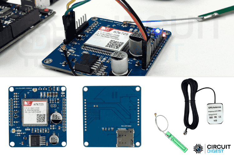
A7672S 4G LTE GNSS Module
The A7672S module combines 4G LTE cellular communication with GNSS (Global Navigation Satellite System, like GPS, BeiDou etc) positioning in a single Arduino-compatible package, making it ideal for remote IoT projects requiring both internet connectivity and location tracking.
Key Features of the A7672S Module
Understanding the A7672S features is crucial for selecting the right cellular module for your project. Here are the key capabilities that make the A7672S Arduino module stand out:
⇒ 4G LTE Connectivity: Supports high-speed cellular internet, allowing your project to send and receive data over the mobile network without Wi-Fi.
⇒ Integrated GNSS Support: Works with GPS, GLONASS, BeiDou, and Galileo satellite systems for accurate and fast location tracking.
⇒ SMS and Voice Call Capability: Can send and receive SMS messages, and even make voice calls—just like a basic mobile phone.
⇒ Arduino-Compatible Interface (UART): Easily connects with Arduino and other microcontrollers via serial communication (TX/RX pins).
⇒ Multiple Protocol Support: Supports TCP/IP, HTTP, FTP, and MQTT protocols, useful for connecting to web servers, cloud platforms, or IoT dashboards.
⇒ Low Power Consumption: Designed for energy-efficient operation, making it suitable for battery-powered devices.
⇒ Compact All-in-One Design: Combines GSM (for mobile network) and GNSS (for GPS) into a single module, saving space and reducing wiring complexity.
⇒ Global Network Support: Works with various LTE bands, so it’s compatible with mobile networks in many countries.
⇒ Real-Time Clock (RTC) Built-in: Useful for timestamping data even without an external RTC module.
The A7672S module is perfect for projects like GPS trackers, remote data loggers, smart farming devices, and any application that needs reliable internet and precise location, even in places where Wi-Fi can't reach.
A7672S 4G LTE GNSS Module Specifications
The A7672S specifications show its versatility in power requirements and operating conditions. The module uses the MIC29302 voltage regulator to provide a stable 3.9V output, allowing flexible power input options for various Arduino projects. This means you can power it with anything from 5V to 12V, making it compatible with common power supplies or USB adapters.
If you’re using a lithium battery, it supports voltages between 3.4V and 4.2V—perfect for standard Li-ion or LiPo cells. If you're using something like an Arduino Uno that operates on 5V logic, you might typically need a level shifter to safely connect the two. However, since this module has a built-in level shifter circuit, no external shifter is required.
On average, the module draws around 500 mA to 1A of current, but during startup, it can spike up to 3 amps. So, a good and stable power supply is essential.
It’s also robust enough for extreme environments, operating reliably in temperatures from -40°C to 85°C, and it can be safely stored up to 90°C. This makes it a solid choice for outdoor and mobile projects.
Next, let’s have a look at the pinouts.
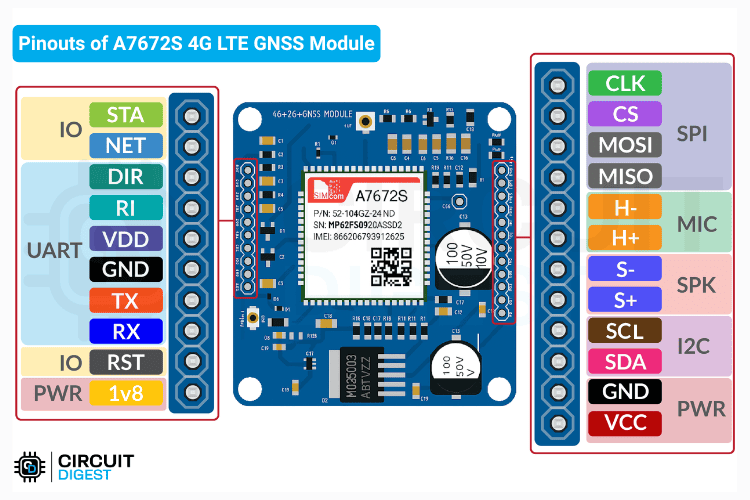
A7672S 4G LTE GNSS Module Pinout
The A7672S module comes with a variety of pins that support multiple communication interfaces and functions, making it versatile for different types of projects. Below you can see the pinout image of the A7672S Module.
STA - Module status indication.
NET - Network Registration status indication.
DTR - UART DTE Ready.
RI - UART Ring Indicator.
VDD - High Reference Voltage for Level Shifter.
GND - Ground.
TX - UART Transmitter.
RX - UART Receiver.
RST - System Reset (Active HIGH).
1V8 - 1.8v 50mA Output Voltage for Level Conversion..
Starting with the status and control pins, STA indicates the module's current status (such as power or activity), while NET shows the network registration status—great for visual feedback using LEDs. The RST pin is used to reset the module and is active high, meaning it triggers a reset when pulled high.
CLK - SPI Clock.
CS - SPI Chip Select.
MOSI - SPI Master Out Slave In.
MISO - SPI Master In Slave Out.
H- - Microphone (-ve).
H+ - Microphone (+ve).
S- - Speaker (-ve).
S+ - Speaker (+ve).
SCL - I2C Serial Clock.
SDA - I2C Serial Data.
GND - Ground.
VCC - Main Input Voltage (5v to 12v, 3A).
For serial communication, the module includes TX and RX, which are used for transmitting and receiving data over UART. Supporting pins like DTR indicate when the host is ready for communication, and RI acts as a ring indicator to notify of incoming calls or messages. VDD provides a high reference voltage input for level shifting when connecting to different logic levels, and 1V8 gives a stable 1.8V output (up to 50mA) that can be used for logic level conversion.
Powering the module is straightforward: VCC is the main input pin accepting 5V to 12V, and it’s recommended to use a power source capable of supplying at least 3A. The module also includes two GND pins for grounding the circuit.
If you're using I2C communication, SDA and SCL are provided for data and clock lines, allowing easy integration with I2C sensors and peripherals.
For audio support, the module includes a built-in interface for connecting external audio devices: S+ and S- are used for connecting a speaker, while H+ and H- are for connecting a microphone, making it possible to build voice call or alert-based systems.
Lastly, for SPI communication, the module features four dedicated pins: MISO, MOSI, CS, and CLK, allowing fast data transfer and compatibility with SPI-based sensors, displays, or memory devices.
With this rich set of interfaces, the A7672S module is capable of handling everything from basic UART communication to full audio and sensor-based applications. Remember, if you're a beginner, you only need to use the UART and power pins; that's already more than enough to get started. Don’t confuse yourself with all the rest.
A7672S 4G LTE GNSS Module Hardware Overview
This section will help you clearly understand the hardware layout of the A7672S development board. Keep in mind that multiple manufacturers produce breakout boards for the A7672S module. While the physical layout, features, and component placement may vary, the core circuitry remains essentially the same.
Below is the version used in our tutorial,
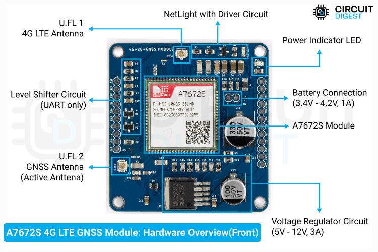
The LDO (Low Dropout Regulator) visible in the bottom-right corner of the board is part of the onboard voltage regulation circuit. It efficiently steps down the input voltage (ranging from 5V to 12V) to a stable 3.9V, which is the required operating voltage for the A7672S module.
Surrounding resistors and capacitors act as filtering components to ensure clean power delivery. This is especially important because cellular modules are sensitive to noise on the power lines, which can negatively impact RF performance and signal stability.
The board also includes a dedicated battery input terminal (3.4V–4.2V, 1A), designed for connecting a Li-ion or LiPo battery. This battery input can be used either as a backup power source in case of primary power loss or as the main supply for portable or low-power applications.
The board includes a built-in level shifter circuit that ensures safe UART communication with microcontrollers operating at different logic voltages (e.g., 3.3V or 5V). This eliminates the need for external level converters, simplifying integration with most Arduino boards and other MCUs.
The A7672S module itself is the central processing unit that handles both 4G LTE cellular communication and GNSS positioning. It integrates the baseband processor, RF frontend, and power management functions in a compact form factor.
The antenna connections are critical - U.FL1 connects to the 4G LTE antenna for cellular communication, while U.FL2 connects to the GNSS antenna ( Active Antenna) for GPS/GLONASS/BeiDou positioning.
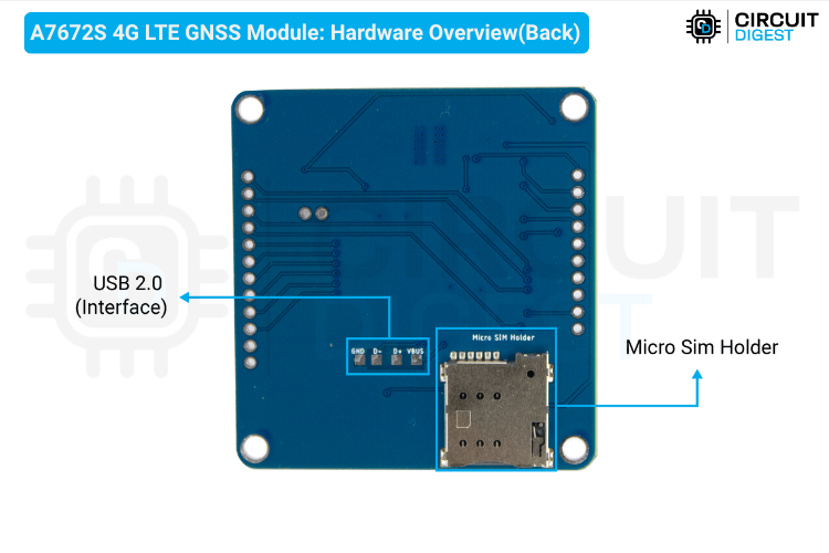
On the back, there is a Micro SIM card slot for inserting your mobile network SIM, allowing the module to register on the 4G network and access cellular services. The USB 2.0 interface provides both data communication and firmware update capabilities.
Interfacing A7672S with Arduino - Circuit Diagram
To keep things simple, we will be using the Serial Monitor alone for debugging. So, the circuit should consist only of the Arduino and the A7672S Module. The circuit connection is quite straightforward.

- The main connections that need to be made are the UART and Power.
- It looks like the TX of the module is connected to the RX of the Arduino, and the RX of the module is connected to the TX of the Arduino.
- For power, the VCC is connected to the 5V pin of the Arduino, and GND to Ground.
- Optionally, you can connect the RST pin. Connecting it to GND for a few milliseconds will reset the module. Below, you can see the fully assembled circuit.
More than just the wire connections, there are two additional connections:
The 4G LTE Network Antenna, and
The GNSS Antenna.
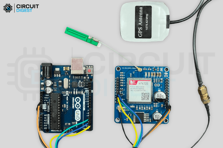
In my case, as I am checking the GPS indoors (inside an office), I used a longer GPS antenna with an SMA connector, along with an SMA to IPEX converter in between.
With this setup, we can now learn more about the AT Commands that are being used.
AT commands of the A7672S Module
Mastering A7672S AT commands is essential for controlling the module's cellular and GNSS functions. These commands allow you to send SMS, make calls, connect to the internet, and retrieve GPS data from any microcontroller or even a simple serial terminal. At the bottom of this page, you will find a simple sketch that turns an Arduino into a USB-to-Serial converter, allowing you to send these commands directly from the Serial Monitor and test them.
The A7672S AT commands are similar to other GSM modules like the SIM800L and SIM900A, making migration from older 2G modules straightforward.
Basic AT Commands
When you enter just AT, the module should reply with OK, confirming that it is powered and serial communication is active.
To set a permanent baud rate, use AT+IPREX=<speed>. A response of OK means it's saved even after a reboot.
The SIM card status can be checked with AT+CPIN?. If the SIM is active, you’ll get +CPIN: READY. Other responses like +CPIN: SIM PIN or +CPIN: SIM PUK indicate the card is locked.
You can retrieve the ICCID using AT+ICCID, which returns a 20-digit number like +ICCID: 8991xxxxxxxxxxxxxxx to verify SIM insertion.
To check signal quality, use AT+CSQ. For example, +CSQ: 15,0 means medium signal with no bit errors. A value of 31 indicates the strongest signal.
The command AT+CREG? helps determine if the module is connected to the mobile network. You’ll get something like +CREG: 0,1 (registered, home) or +CREG: 0,5 (registered, roaming). Before using this, send AT+CREG=1 to enable real-time updates.
To use mobile data services, activate GPRS registration with AT+CGREG=1, and enable the PDP context with AT+CGACT=1,1.
Use AT+CGPADDR=1 to confirm if an IP address has been assigned successfully.
Before accessing GPS features, power on the GNSS module with AT+CGNSSPWR=1. A successful response would be OK followed by +CGNSSPWR: READY!.
AT Commands for Making a Voice Call
This step-by-step sequence outlines the essential commands used to test and initiate a voice call using the A7672S module.
It begins with a basic AT command that returns “OK”, confirming that the module is powered and communicating correctly over the serial interface. The command AT+CSQ provides signal quality in the format +CSQ: xx,yy, where xx is signal strength (0 = worst, 31 = best) and yy is bit error rate (typically 0 for good connections or 99 if unknown).
Using AT+ICCID, the module returns the SIM’s unique 20-digit ICCID (e.g., +ICCID: 8991xxxxxxxxxxxxxxx), helping confirm that the SIM card is properly inserted.
To check network connection, AT+CREG? returns +CREG: n,stat. A stat value of 1 indicates successful registration to the home network, while 5 indicates roaming. If the status is 0, 2, or 3, the module may not be connected yet or may require a better signal.
To make a call, use ATD +91xxxxxxxxxx;. A successful response includes OK and a call status like +CLCC. To end the call, send ATH. Repeated calls without proper termination may result in errors like BUSY or NO CARRIER.
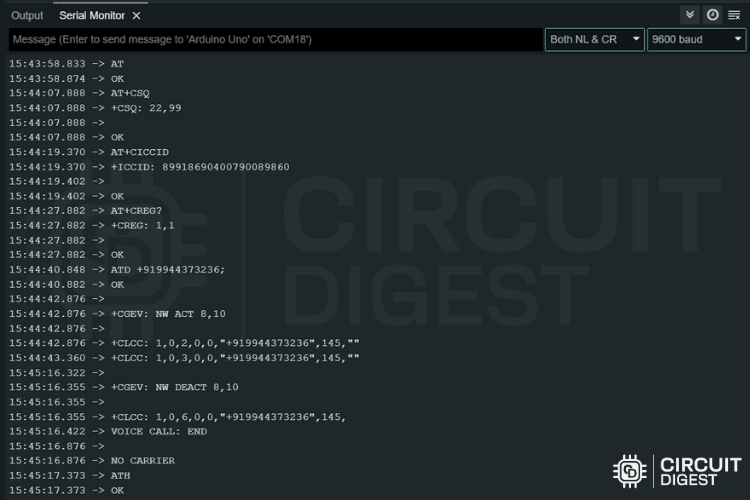
The screenshot above demonstrates the AT command testing process. This call flow is essential for verifying voice functionality and understanding how the module behaves during real-time call operations.
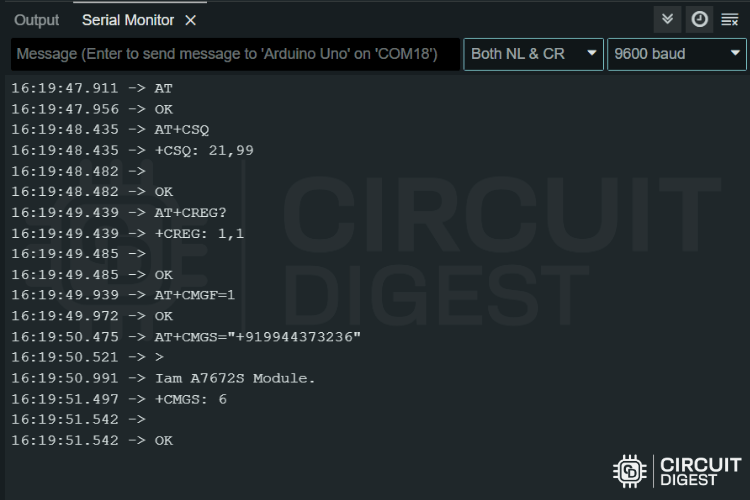
AT Commands for Sending Message
This sequence explains how to send SMS messages using the A7672S module. As always, we begin with basic checks to ensure connectivity and signal quality.
Before sending SMS, the module must be switched to text mode using AT+CMGF=1. Then, you send AT+CMGS="+xxyyyyyyyyyy;" (replace with the correct country code and number). After the > prompt appears, you can type your message and finish it by pressing Ctrl+Z (or sending ASCII code 26). Upon success, the module responds with +CMGS: n, confirming the message has been sent.
AT Commands for Reading GNSS (GPS) Data
The A7672S module has a built-in GNSS engine. To use it, the GNSS hardware must be powered on with the command AT+CGNSSPWR=1. A successful response includes both OK and +CGNSSPWR: READY!.
The AT+CGNSSINFO command provides a long comma-separated string. Here's how to interpret it,
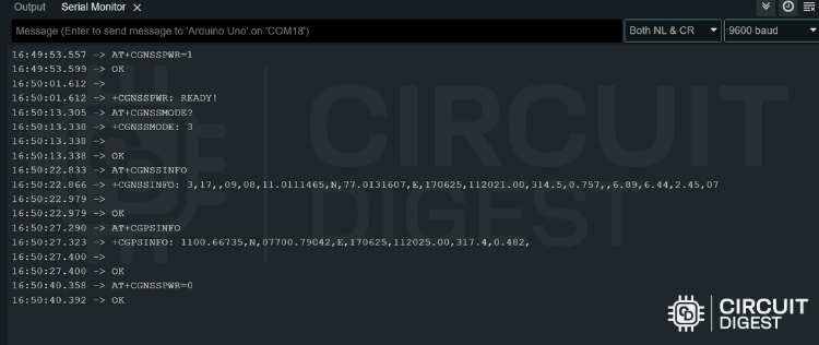
The Fix Mode tells you whether the position is valid. A mode of 3 means a full 3D fix including altitude. The Latitude and Longitude are in decimal degrees. Altitude is in meters, and Speed is in knots (convert to km/h by multiplying by 1.852).
The DOP values reflect the quality of the GPS fix — lower DOP values mean more accurate positioning.
AT Commands for HTTPS Request in A7672S
This entire AT command sequence is designed to send JSON data securely over HTTPS from an A7672S 4G module to a web server, making it highly suitable for IoT telemetry applications like GPS tracking, sensor data logging, smart metering, etc.
The process begins with network initialization, starting with AT+CPIN? to ensure the SIM is ready; the expected response is +CPIN: READY. Next, commands like AT+CREG=1 and AT+CGREG=1 enable registration status reporting for both cellular and GPRS networks. You then verify registration using AT+CREG?, which responds with something like +CREG: 1,1 — the second digit indicates registration (1 = registered on home network, 5 = roaming).
After registering, AT+CGACT=1,1 activates the PDP context, enabling data service, and AT+CGPADDR=1 fetches the assigned IP (e.g., +CGPADDR: 1,10.2.94.78). Once online, you enable verbose errors via AT+CMEE=2 to get detailed error codes, which helps with debugging.
In the SSL configuration section, AT+CSSLCFG="sslversion",0,4 sets the SSL version to TLS 1.2, which is required for most secure APIs. Before any HTTP session, AT+HTTPTERM ensures no previous sessions are active. Then, AT+HTTPINIT initializes the new session.
Next, multiple AT+HTTPPARA commands configure request parameters: you assign the SSL config (SSLCFG), specify the target URL (URL), and set timeouts for connecting and receiving. CONTENT is used to declare the data type (here, application/json), and if your server requires authorization, you set headers using USERDATA.
For sending data, AT+HTTPDATA=174,10000 prepares the module to accept 174 bytes of data, giving you 10 seconds. On receiving the DOWNLOAD prompt, paste your JSON payload (e.g., {"device_id":"Tracker1",...}) and wait for the OK. Then, AT+HTTPACTION=1 performs the actual POST request, and you get a response like +HTTPACTION: 1,200,28, where 200 is the HTTP status code (success) and 28 is the length of the response.
Finally, AT+HTTPREAD can be used to read the response content (e.g., a confirmation message or JSON reply), and AT+HTTPTERM properly ends the session to free resources. This sequence ensures reliable and secure data transfer using HTTPS.
GPS Tracking Demo with A7672S Module and GeoLinker
With a solid understanding of some essential AT Commands, we can now explore a real-world example: building a simple yet functional GPS tracker using the A7672S 4G LTE GNSS Module. For this demonstration, we’ll be using GeoLinker by CircuitDigest, an excellent platform specifically designed to validate the full functionality of the GPS Tracker Projects.
If you're new to GeoLinker or want to learn more about it, we recommend checking out the GPS Visualizer to Upload Data and Visualize GPS Maps for Arduino, ESP32 & other Embedded Devices Article.
The circuit diagram used in this project is identical to the standard interfacing setup for the A7672S module. However, you can easily customize it further by adding optional components depending on your specific use case. Once all the connections are made, your hardware setup should look similar to the image shown below,
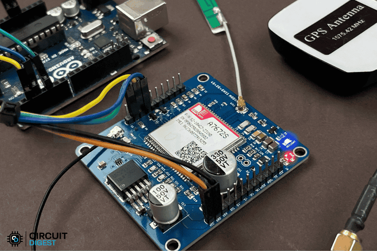
One important thing to keep in mind at this stage is that a valid SIM card is required for the module to function correctly. We tested the module with various SIM cards, including JIO, Airtel, and VI, all of which worked flawlessly.
However, in some instances, the module may not automatically register on the cellular network. In such cases, you can use manual AT commands to initiate registration. Once successfully registered, the NETLIGHT indicator on the module will start blinking, as shown in the GIF below. This blinking pattern confirms that the SIM card is active and connected to the network.
You can now upload the testing code available on the GitHub link provided below. Once the code is uploaded, the tracker will start functioning, and you’ll be able to monitor the GPS data in real time.
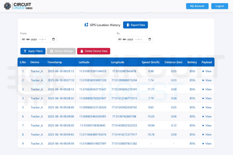
For outdoor testing, we took the device on a short ride around our office campus. Below are screenshots of how the location data was displayed and updated live on the GeoLinker dashboard.
As you can see, the tracker updates its location in real time, and the data points are clearly visible on the interface.
Frequently Asked Questions - A7672S Module
What's the difference between A7672S-FASE and A7672S-LASE?
A7672S-FASE includes GNSS and BLE support for GPS tracking, while A7672S-LASE/LASC variants do not have GNSS capabilities.
Can A7672S work with Arduino Uno?
Yes, the A7672S has built-in level shifting, making it compatible with 5V Arduino boards like Arduino Uno without external level converters.
Which SIM cards work with A7672S in India?
A7672S supports all major Indian networks including Jio, Airtel, and VI. However, some Jio SIMs configured for 5G mode may require network reconfiguration.
GitHub Repository for A7672S
The GitHub repository provides all the essentials to work with the A7672S module, including Arduino code for enabling cellular connectivity and GNSS-based location tracking, support for SMS and cloud communication protocols, and detailed documentation with circuit diagram to guide users through setup and integration for various mobile or remote IoT applications.


Projects using GSM Module
Previously, we have built many tutorials and projects using GSM module. If you want to know more about those topics, links are given below.

Send/Receive SMS with STM32F103C8 and SIM800C GSM Module
In this tutorial, such GSM module will be interfaced with STM32F103C8 ARM microcontroller to send and receive Text Messages (SMS) from the cellular mobile number configured in the program.

Interfacing GSM Module with AVR Microcontroller: Send and Receive Messages
Learn how we can Interface the GSM module (SIM900A) with AVR microcontroller ATmega16 and Send and receive messages using GSM Module.

Interfacing SIM800L GSM/GPRS Module with ESP32
Learn how to interface the SIM800L GSM module with ESP32 for sending SMS, making calls, and enabling cellular communication in IoT and remote monitoring projects.

GSM module Interfacing with PIC Microcontroller - Make and Receive Calls
Learn how to interface a GSM module with PIC16F877A microcontroller to send and receive SMS. Ideal for beginners working on PIC-based IoT or alert systems.
