
GSM modules are interesting to use especially when our project requires remote access. These modules could make all actions that our normal mobile phone could do, like making/receiving a call, sending/receiving a SMS, connecting to internet using GPRS etc. You can also connect a normal microphone and speaker to this module and converse on your mobile calls. This will open doors to lot of creative projects if it could be interfaced with a Microcontroller. Hence in this tutorial we will learn how we can Interface the GSM module (SIM900A) with AVR microcontroller ATmega16 and will demonstrate it by sending and receiving messages using GSM Module.
Materials Required
- Atmega16
- GSM module (SIM900 or any other)
- LCD display
- Push buttons
- 10k resistors, Potentiometer
- Connecting wires
- 12V Adapter
- USBasp programmer
- 10 pin FRC cable
Software Used
We will use CodeVisionAVR software for writing our code and SinaProg software for uploading our code to Atmega16 using USBASP programmer.
You can download these softwares from the given links:
CodeVisionAVR : http://www.hpinfotech.ro/cvavr_download.html
Before going into the schematics and codes, we learn about GSM module and its working.
GSM Module

The GSM module can be used even without any microcontroller by using the AT command mode. As shown above the GSM module comes with a USART adapter which can be directly interfaced to the computer by using a MAX232 module or the Tx and Rx pins can be used to connect it to a Microcontroller. You can also notice the other pins like MIC+, MIC-, SP+, SP- etc where a microphone or a Speaker can be connected. The module can be powered by a 12V adapter through a normal DC barrel jack.
Insert your SIM card in the slot of the module and power it on, you should notice a power LED going ON. Now wait for a minute or so, and you should see a red (or any other colour) LED Flashing once for every 3 seconds. This means that your Module was capable to establish connection with your SIM card. Now you can proceed with connecting you module with Phone or any Microcontroller.
You can build many cool projects using GSM module like:
- Wireless Notice Board using GSM and Arduino
- Automatic Call answering Machine using Arduino and GSM Module
- GSM Based Home Automation using Arduino
- PIR Sensor and GSM Based Security System
Also check all the GSM related projects here.
Communicating with GSM module using AT commands
As you might have guessed it, the GSM module can communicate through Serial communication and could understand only one language and that is “AT commands”. Whatever that you might want to tell or ask to the GSM module it should only be via AT commands. For example if you want to know if your module is active. You should ask (send) a command like “AT” and your module will reply “OK”.
These AT commands are well explained in its data sheet and can be found here in its official datasheet. Okay! Okay! It is a 271 page datasheet and you might take days to read through them. So I have given some most important AT commands below for you to get this up and running soon.
|
AT |
Replies with OK for Acknowledgement |
|
AT+CPIN? |
Check signal Quality |
|
AT+COPS? |
Find service provider name |
|
ATD96XXXXXXXX; |
Call to the specific number, ends with semi-colon |
|
AT+CNUM |
Find the number of SIM card (might not work for some SIM) |
|
ATA |
Answer the Incoming Call |
|
ATH |
Hang off the current Incoming call |
|
AT+COLP |
Show incoming call number |
|
AT+VTS=(number) |
Send DTMF number. You can use any number on your mobile keypad for (number) |
|
AT+CMGR |
AT+CMGR=1 reads message at first position |
|
AT+CMGD=1 |
Delete message at first position |
|
AT+CMGDA=”DEL ALL” |
Delete All messages from SIM |
|
AT+CMGL=”ALL” |
Read all messaged from SIM |
|
AT+CMGF=1 |
Set SMS configuration. “1” is for text only mode |
|
AT+CMGS = “+91 968837XXXX” >CircuitDigest Text<Ctrl+z> |
Sends SMS to a particular number here 968837XXXX. When you see “>” start entering the text. Press Ctrl+Z to send the text. |
|
AT+CGATT? |
To check for internet connection on SIM card |
|
AT+CIPSHUT |
To close TCP connection, meaning to disconnect form internet |
|
AT+CSTT = “APN”,”username”,”Pass” |
Connect to GPRS with your APN and Pass key. Can be obtained from Network Provider. |
|
AT+CIICR |
Check if SIM card has data pack |
|
AT+CIFSR |
Get IP of the SIM network |
|
AT+CIPSTART = “TCP”,”SERVER IP”,”PORT” |
Used to set a TCP IP connection |
|
AT+CIPSEND |
This command is used to send data to server |
Here we will use AT+CMGF and AT+CMGS command to send messages.
If you have used GSM module with Arduino, while receiving messages you can use +CMT: command to view the mobile number and text message on serial monitor. Text message comes on second line as shown in picture.
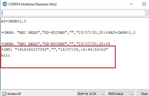
We will scan this +CMT: command to check whether message is available or not.
ATMega16 GSM Module Interfacing Circuit Diagram

Connections will be as follows
- Tx and Rx of GSM module to Rx (Pin14) and Tx (Pin15) of Atmega16 respectively.
- Push Buttons to PD5 (Pin19) and PD6 (Pin20).
- LCD connections:
- RS - PA 0
- R/W - PA1
- EN - PA2
- D4 - PA4
- D5 - PA5
- D6 - PA6
- D7 - PA7
Creating the Project for ATmega16 using CodeVision
After installing CodeVisionAVR and SinaProg softwares, follow the below steps to create project and writing code:
Already uploaded
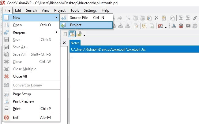
Step 1. Open CodeVision Click on File -> New -> Project. Confirmation Dialogue box will appear. Click On Yes
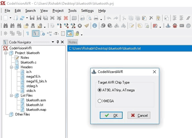
Step 2. CodeWizard will open. Click on first option i.e. AT90, and click OK.
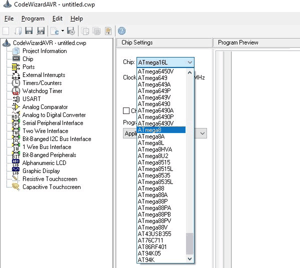
Step 3:- Choose your microcontroller chip, here we will take Atmega16L as shown.
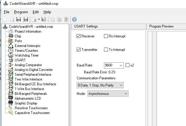
Step 4:- Click on USART. Select Receiver and Transmitter by clicking on it. As shown below:
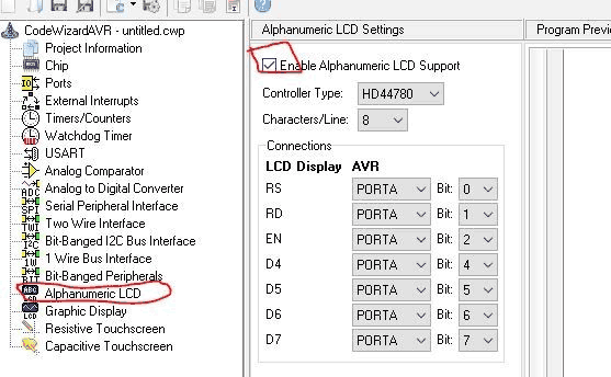
Step 5:- Click on Alphanumeric LCD and select Enable Alphanumeric LCD support.
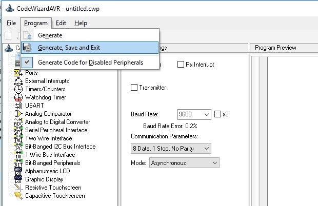
Step 6:- Click on Program -> Generate, Save and Exit. Now, more than half of our work is completed
Step 7:- Make a New folder on desktop so, that our files remains in folder otherwise it we will be scattered on whole desktop window. Name your folder as you want and I suggest use the same name to save program files.
We will be having three dialogue box one after other to save files.
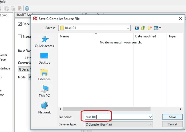
Do the same with other two dialogue boxes which will appear after you save the first.
Now, your workspace looking like this.
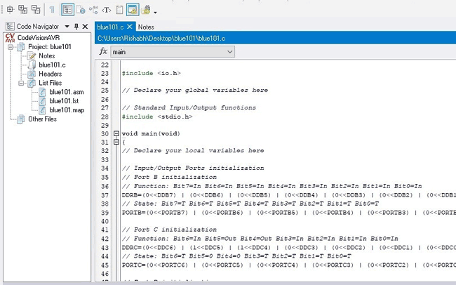
Our most of the work is completed with the help of the Wizard. Now, we have to write code for GSM only.
Code and Explanation
All the header files are automatically attached after creating the project, you have to just include delay.h header file and declare all the variables. Complete code is given at the end of this tutorial.
#include <io.h>
// Alphanumeric LCD functions
#include <alcd.h>
#include <delay.h>
// Standard Input/Output functions
#include <stdio.h>
unsigned char received_value(void);
unsigned char received_data,a,b,c;
unsigned int z;
unsigned char msg[15];
unsigned char cmd_1[]={"AT"};
unsigned char cmd_2[]={"AT+CMGF=1"};
unsigned char cmd_3[]={"AT+CMGS="};
unsigned char cmd_4[]={"Call me"};
unsigned char cmd_5[]={"Receiver mobile number"};
Make a function to receive data from UDR register. This function will return received data.
unsigned char received_value(void)
{
while(!(UCSRA&(1<<RXC)));
{
received_data=UDR;
return received_data;
}
}
Come to the while loop in which we create two if statements, one for sending message and other for receiving. Send button is connected with PIND6 of ATmega and receive message button with PIND5.
When PIND6 (Send Button) is pressed first if statement will execute and all the commands to send message will execute one by one.
while(1){
 //  lcd_clear();
      lcd_putsf("Send->bttn 1");
      lcd_gotoxy(0,1);
        lcd_putsf("Receive->buttn 2");

          if(PIND.6 == 1){
          lcd_clear();
  lcd_gotoxy(0,0);
lcd_putsf("Sending Msg...");
for(z=0;cmd_1[z]!='';z++)
{
UDR = cmd_1[z];
delay_ms(100);
}
UDR = ('\r');
delay_ms(500);
for(z=0;cmd_2[z]!='';z++)
{
UDR = cmd_2[z];
delay_ms(100);
}
…
..
If Receive message button is pressed, while (b!='+') loop will check whether CMT command is present or not. If present, second while loop will execute and go to second line of the command and print the message on LCD one by one.
   while(PIND.5 == 1){
      lcd_clear();
       lcd_gotoxy(0,0);
   lcd_putsf("Receiving Msg...");
   b= received_value ();
while (b!='+')         {
b= received_value ();
}
b= received_value ();
if(b=='C')
{
 b= received_value ();
…
..
This loop takes the program to second line of command and store the message in the array.
while (b!=0x0a)
 {
b= received_value ();
}
for(b=0;b<3;b++)   {
             c=received_value();
             msg[b]=c;
}
..
..
This for loop is to display the message on LCD.
for(z=0;z<3;z++)
{
a=msg[z];
lcd_putchar(a); // PRINT IN lcd
delay_ms(10);
}
Complete code with Demo Video is given below, now we have to Build our project.
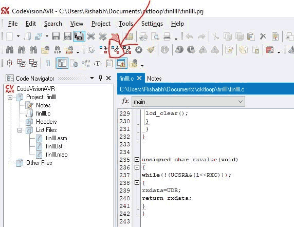
Build the Project
Click on Build the project icon as shown.
After building the project, a HEX file is generated in the Debug-> Exe folder which can be found in the folder which you have made previously to save your project. We will use this HEX file to upload in Atmega16 using Sinaprog software.
Upload the code to Atmega16
Connect your circuits according to given diagram to program Atmega16. Hookup the one side of FRC cable to USBASP programmer and other side will connect to SPI pins of microcontroller as described below:
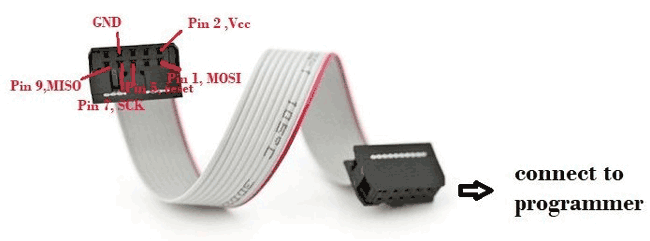
- Pin1 of FRC female connector -> Pin 6 ,MOSI of Atmega16
- Pin 2 connected to Vcc of atmega16 i.e. Pin 10
- Pin 5 connected to Reset of atmega16 i.e. Pin 9
- Pin 7 connected to SCK of atmega16 i.e. Pin 8
- Pin 9 connected to MISO of atmega16 i.e. Pin 7
- Pin 8 connected to GND of atmega16 i.e. Pin 11
We will upload the above generated Hex file using the Sinaprog, so open it and Choose Atmega16 from Device drop down menu. Select the HEX file from the Debug-> Exe folder as shown.
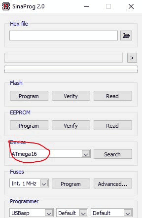
Now, Click on Program and your code will be burned in ATmega16 Microcontroller.
You are done and your Microcontroller is programmed. Just press the buttons to send and receive the messages form GSM and ATmega16 microcontroller.
Complete code and demonstration Video is given below.
Complete Project Code
#include <io.h>

// Alphanumeric LCD functions

#include <alcd.h>

#include <delay.h>

// Standard Input/Output functions

#include <stdio.h>

unsigned char received_value(void);

unsigned char received_data,a,b,c;

unsigned int z;

unsigned char msg[15];

unsigned char cmd_1[]={"AT"};

unsigned char cmd_2[]={"AT+CMGF=1"};

unsigned char cmd_3[]={"AT+CMGS="};

unsigned char cmd_4[]={"Call me"};

unsigned char cmd_5[]={"Receiver mobile number"};
void main(void)

{

// Port A initialization

// Function: Bit7=In Bit6=In Bit5=In Bit4=In Bit3=In Bit2=In Bit1=In Bit0=In

DDRA=(0<<DDA7) | (0<<DDA6) | (0<<DDA5) | (0<<DDA4) | (0<<DDA3) | (0<<DDA2) | (0<<DDA1) | (0<<DDA0);

// State: Bit7=T Bit6=T Bit5=T Bit4=T Bit3=T Bit2=T Bit1=T Bit0=T

PORTA=(0<<PORTA7) | (0<<PORTA6) | (0<<PORTA5) | (0<<PORTA4) | (0<<PORTA3) | (0<<PORTA2) | (0<<PORTA1) | (0<<PORTA0);

// Port B initialization

// Function: Bit7=In Bit6=In Bit5=In Bit4=In Bit3=In Bit2=In Bit1=In Bit0=In

DDRB=(0<<DDB7) | (0<<DDB6) | (0<<DDB5) | (0<<DDB4) | (0<<DDB3) | (0<<DDB2) | (0<<DDB1) | (0<<DDB0);

// State: Bit7=T Bit6=T Bit5=T Bit4=T Bit3=T Bit2=T Bit1=T Bit0=T

PORTB=(0<<PORTB7) | (0<<PORTB6) | (0<<PORTB5) | (0<<PORTB4) | (0<<PORTB3) | (0<<PORTB2) | (0<<PORTB1) | (0<<PORTB0);

// Port C initialization

// Function: Bit7=In Bit6=In Bit5=In Bit4=In Bit3=In Bit2=In Bit1=In Bit0=In

DDRC=(0<<DDC7) | (0<<DDC6) | (0<<DDC5) | (0<<DDC4) | (0<<DDC3) | (0<<DDC2) | (0<<DDC1) | (0<<DDC0);

// State: Bit7=T Bit6=T Bit5=T Bit4=T Bit3=T Bit2=T Bit1=T Bit0=T

PORTC=(0<<PORTC7) | (0<<PORTC6) | (0<<PORTC5) | (0<<PORTC4) | (0<<PORTC3) | (0<<PORTC2) | (0<<PORTC1) | (0<<PORTC0);

// Port D initialization

// Function: Bit7=In Bit6=In Bit5=In Bit4=In Bit3=In Bit2=In Bit1=In Bit0=In

DDRD=(0<<DDD7) | (0<<DDD6) | (0<<DDD5) | (0<<DDD4) | (0<<DDD3) | (0<<DDD2) | (0<<DDD1) | (0<<DDD0);

// State: Bit7=T Bit6=T Bit5=T Bit4=T Bit3=T Bit2=T Bit1=T Bit0=T

PORTD=(0<<PORTD7) | (0<<PORTD6) | (0<<PORTD5) | (0<<PORTD4) | (0<<PORTD3) | (0<<PORTD2) | (0<<PORTD1) | (0<<PORTD0);
// USART initialization

// Communication Parameters: 8 Data, 1 Stop, No Parity

// USART Receiver: On

// USART Transmitter: On

// USART Mode: Asynchronous

// USART Baud Rate: 9600

UCSRA=(0<<RXC) | (0<<TXC) | (0<<UDRE) | (0<<FE) | (0<<DOR) | (0<<UPE) | (0<<U2X) | (0<<MPCM);

UCSRB=(0<<RXCIE) | (0<<TXCIE) | (0<<UDRIE) | (1<<RXEN) | (1<<TXEN) | (0<<UCSZ2) | (0<<RXB8) | (0<<TXB8);

UCSRC=(1<<URSEL) | (0<<UMSEL) | (0<<UPM1) | (0<<UPM0) | (0<<USBS) | (1<<UCSZ1) | (1<<UCSZ0) | (0<<UCPOL);

UBRRH=0x00;

UBRRL=0x33;
lcd_init(16);

lcd_clear();

lcd_gotoxy(0,0);

lcd_putsf("Welcome...");

delay_ms(2000);

lcd_clear();

lcd_putsf("Initialising GSM");

delay_ms(4000);

lcd_clear();
while(1){

      lcd_putsf("Send->bttn 1");

      lcd_gotoxy(0,1);

        lcd_putsf("Receive->buttn 2");
          if(PIND.6 == 1){

          lcd_clear();

  lcd_gotoxy(0,0);

lcd_putsf("Sending Msg...");

for(z=0;cmd_1[z]!='';z++)

{

UDR = cmd_1[z];

delay_ms(100);

}

UDR = ('\r');

delay_ms(500);

for(z=0;cmd_2[z]!='';z++)

{

UDR = cmd_2[z];

delay_ms(100);

}

UDR = ('\r');

delay_ms(500);

for(z=0;cmd_3[z]!='';z++)

{

UDR = cmd_3[z];

delay_ms(100);

}

UDR = ('"');

delay_ms(100);

for(z=0;cmd_5[z]!='';z++)

{

UDR = cmd_5[z];

delay_ms(100);

}

UDR = ('"');

delay_ms(100);

UDR = ('\r');

delay_ms(500);

for(z=0;cmd_4[z]!='';z++)

{

UDR = cmd_4[z];

delay_ms(100);

}

UDR = (26);                   // ctrlZ-> to send the message

delay_ms(500);

lcd_clear();

  lcd_gotoxy(0,0);

lcd_putsf("Message Sent.");

delay_ms(1000);

lcd_clear();

}
   while(PIND.5 == 1){

      lcd_clear();

       lcd_gotoxy(0,0);

   lcd_putsf("Receiving Msg...");

   b= received_value ();

while (b!='+')            // infinite loop when + equal to +. otherwise until the loop infinite

{

b= received_value ();

}

b= received_value ();

if(b=='C')

{

 b= received_value ();

if(b=='M')

{

b= received_value ();

if(b=='T')

{

b= received_value ();

if(b==':')

{

b= received_value ();

while (b!=0x0a)                          // waiting upto next line if no means till loop infinte

{

b= received_value ();

}

for(b=0;b<3;b++)   {

             c= received_value ();

             msg[b]=c;

}

    lcd_clear();
for(z=0;z<3;z++)

{

a=msg[z];

lcd_putchar(a);                                // PRINT IN lcd

delay_ms(10);

}

}

}

}

}

 delay_ms(3000);

 lcd_clear();

 }

 }

}

unsigned char received_value(void)

{

while(!(UCSRA&(1<<RXC)));

{

received_data=UDR;

return received_data;

}

}
Comments
and also what is "call me" ?

hello thanks for this perfect project
should we write our phone number in this array : "unsigned char cmd_5[]={"Receiver mobile number"};" ?