

Switch Mode Power Supplies (SMPS) are one of the most generally used AC-DC Converters on the market as they accept 110V/230V AC as input and convert it to a desirable DC voltage level, making them useful for a wide range of applications. These are omnipresent, from smartphone chargers to lab bench power supplies to medical tools. We've already developed a few SMPS circuits, such as this 5V 2A SMPS circuit, a 12V 1A TNY268 SMPS circuit, and a 12V 1A Viper-based CV Circuit. However, we did not discuss a Constant Current (CC) with a Constant Voltage (CV) power supply in any of those projects. CC and CV configuration is needed to build Lithium Battery Chargers, in this article we will design and build a 12.6V Li-ion battery charger to charge our 12V battery pack which we built in our previous tutorial. Constant current circuits are extremely helpful as they can be used to safeguard your circuit from overcurrent, as well as charge lithium batteries according to manufacturer requirements. It can also be used as a constant current LED driver to keep your LEDs from burning out. So, in this project, we will be adding in constant current capabilities to our Viper22A-based power supply and will document the entire construction process.
Viper22A Based SMPS Circuit Design Specification
Before we start our SMPS design, we need to shortlist the specifications because different types of SMPS work in different environments and they have input and output specifications. We also need to consider if the SMPS is inside an adapter or if it's in an open environment.
Input Specification
The SMPS circuit we are building will have an AC input voltage rating of 220V-240V as it's the standard Indian specification. This is also the rated input voltage for EU.
Output Specification
The output voltage of the power supply will be 12.6V with 1.3A Constant Current. The output power will be 16.8 watts. As discussed earlier, the SMPS will work in both Constant Current and Constant voltage mode, which means the current will be limited to 1.3A considering how big of a load is attached.
Output Ripple
As the purpose of designing a constant current supply is to use it as a LED Driver or a battery charger, the output ripple specification will not matter that much. But if you are using this power supply to power highly sensitive electronics, then you need to consider that a good power supply will have a maximum output ripple voltage of 30mV pk-pk. The output ripple voltage depends upon two major factors which are the Transformer construction and the output filter, so we need to consider the two factors in our design. We are going to order the transformer from a professional manufacturer and for the capacitor, we are going to use a low ESR value capacitor.
Input & Output Protection
There are various types of protection circuits available that can be employed for the safe and reliable operation of the SMPS, but the protection system can be divided into two categories: input protection and output protection. The input protection circuit protects the SMPS from the transient and high input voltage. The output protection circuit protects the load device from getting damaged. Input surge protection will be used with a maximum operating input voltage of 275VAC. Also, to deal with EMI issues, a common mode filter will be used for blanking out the generated EMI. On the Output side, we will include short circuit protection and over-voltage protection circuit.
Selection of the SMPS Driver IC
To build a proper working SMPS we will be needing a PMIC or power management IC, and as we have discussed earlier, we will be using the Viper22A SMPS controller IC. The circuit will have the following features.
- 16.38W output, 12.6V CV and 1.3A CC.
- Standard (220-260) V input voltage rating
- Input surge protection. Maximum input voltage 275VAC.
- Output short circuit, overvoltage and overcurrent protection.
- Constant voltage operations.
From the above requirement, we have a lot of ICS to choose from but as we have mentioned earlier we will be using the viper22A IC as it is cheap and readily available in the market, and from the datasheet of the Viper22A, we can see that the power capabilities are within our requirement for the DIP Package, so we will be using that IC.
| Main Type | SO-8 | DIP-8 |
|---|---|---|
| European(195-265 Vac) | 12W | 20W |
| US / Wide Range(85-265 Vac) | 7W | 12W |
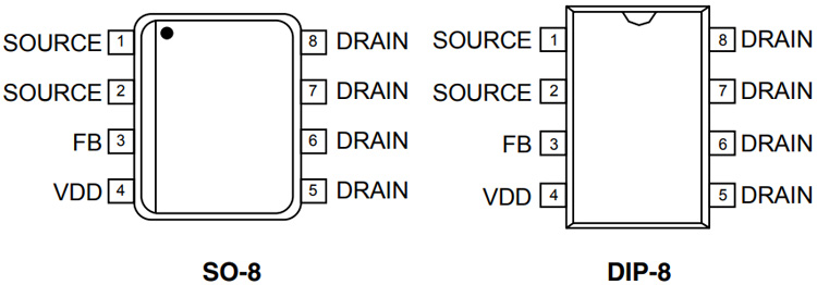
In the above image, the typical power capabilities of the Viper22A IC are shown. As you can see, the DIP-8 version IC with an input voltage of 195-265V can deliver 20W of power. The pinout of the Viper22A IC is given below.
Components Required to build a 12v lithium battery charger
The components required to build the Viper22A-based SMPS circuit are listed below. Most of the components that are used to build this project can be found in your local hobby store or any online store. The Complete BOM of the Viper22A-based battery charger circuit is shown below.
- VIper22A Driver IC - 1
- EE25 SMPS Transformer - 1
- 0.15nF, 250V AC Capacitor - 1
- 100uF, 16V Capacitor - 2
- 10K Resistor-1
- 1K Resistor - 1
- 680R Resistor - 1
- 4.7K Resistor - 1
- 10 Ohms Resistor -2
- 180K Resistor - 1
- 2.2K resistor - 1
- 22uF,400V Capacitor - 1
- 27K Resistor - 1
- 3.3uH,1A inductor -1
- 4.7uF,16V Capacitor - 1
- 9.1K Resistor - 1
- DB107G Bridge Rectifier - 1
- FR107 Fast Recovery Diode - 1
- LM358 Op-amp - 1
- EL817 Optocoupler - 1
- SR360 Schottky Diode - 1
- T500mA Slow Blow Fuse - 1
- TL431 - 1
- UF4007 - 1
- LED Red - 1
- LED Green - 1
- 1R,2W Resistor - 3
- 1000uF,16V Capacitor - 1
- 0.1uF,16V Capacitor - 4
Circuit Diagram of the Viper-Based CC/CV Battery Charger
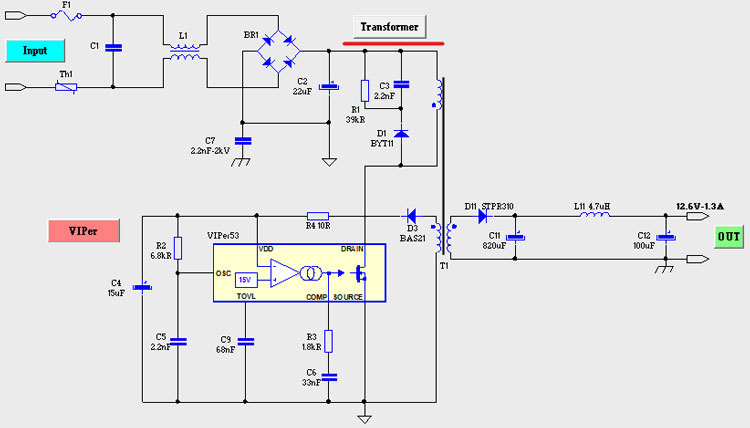
We started designing our circuit by using the power supply design software from Viper. You can download VIPer Design Software Version 2.24. You need to be specific with this version because the latest version of this software from ST does not support the viper22A IC, by selecting the input and output specification, the complete power supply circuit can be generated. The complete circuit for the Viper22A-based CC/CV Battery Charger is shown below.

- Input Surge and Fault Protection
- Input Filter
- AC-DC Conversion
- Driver Circuit or Main Switcher IC
- Clamp Circuit
- EMI Filter
- Secondary Rectifier
- Filter Section
- Feedback section
- Constant Current Section
Input Surge and SMPS Fault Protection
The input surge and fault protection section consist of three parts: First is the Slow Blow Fuse, next is the 10 OHM NTC and finally, we have a 7mm MOV(Metal Oxide Varistor) of 250V, as the max input voltage rating of the VIper22A IC is 265V. During a high voltage surge, the MOV will become dead short, and the fuse will blow up protecting the IC from the high input voltage. The fuse used in an SMPS circuit will have to be a slow-blow type fuse because there will be a huge current flow when the circuit is powered on because of the capacitor. NTC is there to limit the inrush current that is flowing in the first two or three bootup cycles.
Input Filter
For the Input filter, we are using a 0.15nF,250V AC Capacitor. The capacitor is an X-type Capacitor and we have used this type of capacitor in our Transformer less power supply design.
AC-DC Conversion
The main component of the AC-to-DC converter is a Full Bridge Rectifier and for this reason, we are using the DB107 1A Rectifier IC. To filter the noisy DC signal to a smooth DC signal, we are using a 22uF,400V Low ESR Capacitor.
Driver Circuit or Main Switching IC
The Viper22A is the main switching component of our power supply and the device needs power from the auxiliary winding of the transformer to start the switching process. Once the switching voltage is there and it's greater than 9V the switch across the main transformer starts with a built-in MOSFET.
Clamp circuit or Transient Clamp Circuit
The transformer itself is a big inductor. And as with any inductor, it creates a high voltage spike during the turn-off period of the transformer, which could damage the Viper22IC. So to prevent this, we need to use a transient voltage suppressor circuit. The D5, R2, and C7 are what make this circuit.
Secondary Rectifier
The High-Frequency output of the Transformer is rectified and filtered by an SR360 Diode D1. The maximum output current of the diode is 3A so it can easily handle the maximum output current of our power supply which is 1.3A.
Filter Section
In the schematic, C3, L3, and C13 make our LC PI filter. The LC filter is what provides better ripple rejection across the output of the supply.
Feedback Section
The Total feedback section consists of TL431(U2), LM358N(IC1), PC817(OK2), and two LEDs LED1, LED2. The TL431 senses the output voltage and puts out a constant voltage of 2.5V. Now, this 2.5V is compared with the output voltage by op-amp (IC1B), and the feedback from the voltage is lowered with a voltage divider (R7 and R5). Now when the voltage at the non-inverting input of the supply is greater than the inverting input, the output of the op-amp goes high and the LED1 lights up indicating that it's in Constant Voltage or CV mode. Now the optocoupler turns on and it provides some voltage on the feedback pin of the VIPER22A IC and the viper adjusts its switching speed accordingly.
Now for the constant current portion, the operation is almost the same as the constant voltage. The resistors R8, R9 along with R13 form a voltage divider. And this voltage is compared with the voltage drop across the 0.33Ohms resistor, which we have made by paralleling three 1 Ohms resistors. Now if the Voltage at pin3 of the op-amp is higher than pin 2 the output of the op-amp goes high, the LED2 turns on and now controls the optocoupler and the charger module is working in the CC mode.
PCB Design for 12V Battery Charger using Viper22A
The PCB for CC-CV Charger is a simple single-sided board. I have used Eagle to design my PCB but you can use any Design software of your choice. The 2D image of my board design is shown below.

The Top and bottom side of the PCB is shown above. As you can see on the bottom side I have used polygons to ensure sufficient current can flow through it, the thick polygons also act as a heat sink to dissipate heat. The complete design files with the schematic PDF can be found in the link given below.
- Download Gerber files of Viper22A Based CC/CV Flyback Converter PCB
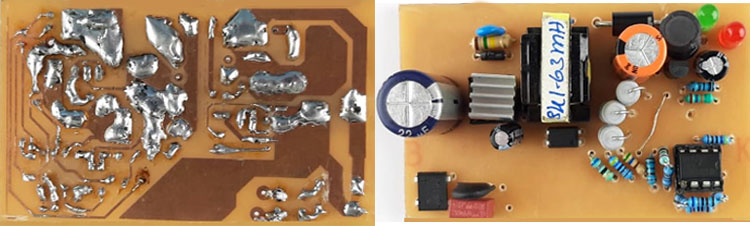
For convenience and testing, we have made a handmade version of the PCB and the top and bottom side after soldering is shown above.
Transformer Construction for the Viper22A-based SMPS Circuit
As we have mentioned earlier, you need the viper design software to set the Input and output parameters, once you have set that you need to click on the Transformer button.
Once you click on the transformer button, you will get something like the image shown below.
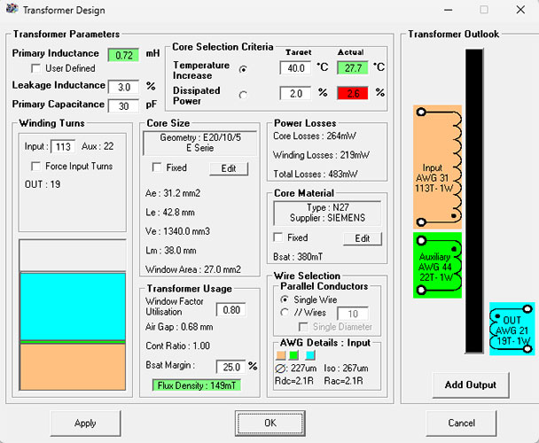
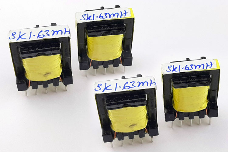
The Core is E20/10/5 with an air gap of 0.68mm. The primary inductance is 0.72mH. The primary turns ratio is 113 Turns with 31 AWG wire. The Auxiliary Wire is 22 Turns with 44 AWG wire. The output windings are made with 19 Turns with 21 AWG wire. With all the information from the Transformer Design tool, we ordered our transformer from a professional construction house and after a week we received our consignment, and the transformers look something like the image shown below.
Testing the Viper22A Based SMPS Circuit
To test the circuit, we have our test setup which is shown below. To measure the output voltage, we are using a multimeter and to measure the current we are using a clamp meter.
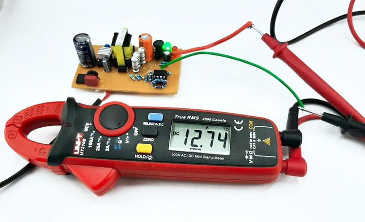
Now as you can see the circuit is powered on and, on the output, we are getting 12.7 volts which make this circuit perfect for 3S battery pack charging.

Now as you can see in the image, we have attached the load to the output of the power supply. The load is two 10 ohms resistors in parallel which makes it 5 ohms load and as you can see there is a 900mA current flow through the resistor. The value of the current is lower because at the time of building the circuit, we did not have a 9.1K resistor with us and we need to put some resistors in series to get that 9.1K value and that is the reason why we are not getting full 1.3A at the output.
Problems while Building the Circuit with Solutions
There are many problems that we have encountered while building the circuit. The biggest of them all is duplicate ICs that we have got our hands on. In the original IC, pin no 5,6,7, and 8 are shorted, but in the duplicate IC pin no 7 and 8 are shorted, and pin no 5 and 6 had no connection with pin 7 and 8.
Next, you need to observe the auxiliary voltage of the transformer. If the auxiliary voltage of the transformer is not greater than 9V the IC will not start its operation.
The next problem was with the constant current design. The Viper IC is not designed for constant current operation, and we had to add an additional circuit to enable constant current mode for Viper IC. On the other hand, if we had used a Power Integrations IC, it would have a current limiting functionality built in, but the viper IC doesn’t have that functionality.

hi
thank you very much for your great project. Unfortunatly, the link to download the gerber file is wrong. I would be very grateful if you could correct it.