

In the modern era, almost every household electronics works on Direct Current (DC) but we get Alternating Current (AC) from power generation plants via transmission lines becuase AC can be transmistted more efficiently than DC in lower cost. So every appliance which works on DC has and AC to DC converter circuit. We previously built a 5v cell phone charger which also has a AC-DC converter circuit in it.
There are mainly two types of converters widely used for AC-DC conversation purpose.
One is the traditional Transformer-based linear converter which uses a simple diode bridge, capacitor, voltage regulator. Simple Diode Bridge can be constructed either with single semiconductor device like DB107 or with 4 independent diodes like 1N4007. The other type of converter is SMPS or Switch mode power supply which uses high-frequency small transformer and a switching regulator to provide DC output.
In this project, we will discuss traditional Transformer based design which use simple diodes and capacitor to convert the Alternating current into Direct Current and an optional voltage regulator to regulate the output DC voltage. The project will be an AC-DC converter using Transformer with an input voltage of 230V and output of 12V 1A.
Components Required
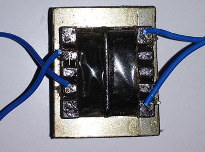
1.Transformer with 1A 13V Rating
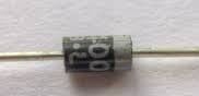
2.4 pcs 1N4007 Diodes
3.A 1000uF Electrolytic capacitor with the 25V rating.
4.Few single strand wires
5.Breadboard
6.LDO or a Linear Voltage Regulator as per specification (Here LM2940 used).
7.A multimeter to measure the voltage.
Circuit Diagram and Explanation

The schematic for this AC-DC converter circuit is simple. The transformer is used to step down the 230V AC to 13V AC.
Four general purpose rectifier diode 1N4007 are used here to retify the AC input. 1N4007 has a peak repetitive reverse voltage of 1000V with an average rectified forward current of 1A. These four diodes are used to convert the 13V AC output across the transformer. The diodes are used to make a bridge converter which is an essential part of the AC to DC conversion circuit. To learn more about Bridge rectifier circuit, follow the link.
Filter capacitor, C1 is added after the bridge converter to smooth out the output voltage.
The LDO, IC1 is also connected to regulate the output voltage.
Working of the AC to DC Converter Circuit
A step-down transformer is used to convert the high voltage AC to the low voltage AC. The transformer is PCB mounted and it is a 1-ampere 13-volt transformer. However, during the load, the transformer voltage drops approximately 12.5-12.7 volt.
The essential part of the circuit is a diode bridge which consists of four diodes. The diode is an electronic semiconductor device which converts the alternating current to direct current.
The flow of current inside the diode bridge can be seen in the below image.

Here two diodes D2 and D4 block the negative peak of the alternating current and make the current flow into the one direction. This is a full bridge rectifier that means the diode bridge rectify both the positive and negative peak of the AC signal.
The large capacitor C1 gets charged during the conversion and smooth out the output voltage. But at the end result, this is not a regulated voltage output. Here the voltage regulation is done by the LDO, LM2940, which is IC1 in the schematic.
The LDO, LM2940 is a 3 pin device into TO220 package. LDO stands for low dropout voltage. The pin diagram can be shown in the below image.
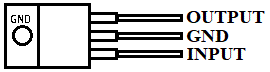
Some voltage regulators have limitations on input voltage which is required to provide guaranteed voltage regulation across the regulator output. In few linear regulators, it is denoted that it requires minimum 2 volts difference in between input voltage and output voltage, that means for regulated 12 volts output, the regulator requires at least 14 volts input voltage for guaranteed 12 volts regulated output voltage. In General, Low Dropout Voltage regulators (LDOs) requires very minimum voltage differences between input and output. For LM2940 datasheet it is minimum 0.5-volt difference requires in between the input and the output. We used a fixed voltage series LDO regulator from Texas Instruments. The LM2940, which has 12 volts output rating.
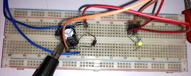
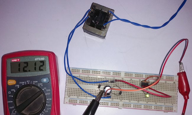
The output can be perfectly seen in the below image.
Check the complete working in the video given at the end.
Transformer-based AC to DC converter is very common where the high voltage AC to DC conversion is required. It is most commonly in amplifier systems, various power adaptors, soldering stations, testing equipment etc.
Limitations of Transformer based AC-DC Converter Circuit
Transformer-based AC to DC conversion is a common choice where DC is required but it has certain drawbacks.
1.Any situations where the input AC voltage has possibilities to fluctuate or if the AC voltage drops significantly, the output AC voltage across the transformer also gets dropped. So a 230V AC to 12V DC converter cannot be powered in 110V AC line. To address this isse, an additional setting is provided for different input voltage levels.
2.Despite not having a universal input voltage range, it is a costly choice, as the transformer itself costs more than 60% of the total manufacturing cost of the converter circuit.
3.Another limitation is low conversion efficiency. The transformer gets heat up and the waste unnecessary energy.
4.The Transformer is heavy stuff which unnecessarily increases the weight of the product.
5.Due to the transformer, the bigger space is required inside the product to fit the converter circuit or at least the transformer.
To overcome these limitations, SMPS or switch mode power supply is a preferable choice.
