
If you think about future technologies then the two names, which immediately comes in your mind, are Artificial Intelligence (AI) and Internet of Things (IoT). AI is still in its initial stage and there is lot more to be developed. But IoT is in Growth stage and lot of IoT based products are already there in the market. Also there are many tools and hardware available in the market to make your product talking with ‘things’ in the internet. Among them ESP8266 is the most popular, cheap and easy-to-use module, which can connect your hardware to the Internet.
We have developed lot of IoT Projects using ESP8266, which not only includes basic interfacing with other microcontrollers like Arduino, PIC, AVR but also includes many intelligent projects like IOT based Air Pollution Monitoring, Vehicle Tracking on Google Maps, IOT based Voice Controlled Home Automation etc. Today in this tutorial, we use ESP8266 to connect STM32F103C8 to the internet. Here we will interface ESP8266 Wi-Fi module with our Blue Pill STM32F103C8 board and send the data to a webpage hosted on ESP8266 webserver.
Components Required
- Blue Pill STM32F103C8 board
- ESP8266 Wi-Fi module
- Laptop & Wi-Fi hotspot
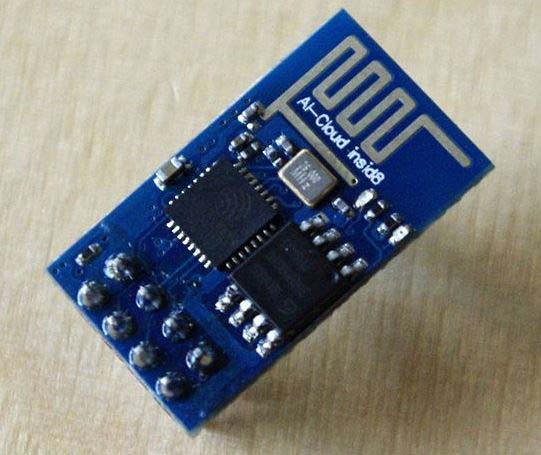
ESP8266 Wi-Fi Module
Most people call ESP8266 as a WIFI module, but it is actually a microcontroller. ESP8266 is the name of the microcontroller developed by Espressif Systems which is a company based out of shanghai. This microcontroller has the ability to perform WIFI related activities hence it is widely used as a WIFI module.
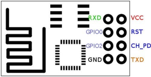
- GND, Ground (0 V)
- TX, Transmit data bit X
- GPIO 2, General-purpose input/output No. 2
- CH_PD, Chip power-down
- GPIO 0, General-purpose input/output No. 0
- RST, Reset
- RX, Receive data bit X
- VCC, Voltage (+3.3 V)
AT command is used for communicating with ESP8266. The table below shows some of useful AT commands
|
AT COMMANDS |
USE |
|
AT |
Acknowledgement returns ‘OK’ |
|
AT+RST |
RESTART module |
|
AT+GMR |
Shows FIRMWARE DETAILS |
|
AT+CWMODE=1 or 2 or 3 |
Wi-Fi mode 1-Station, 2- AP ,3-Both |
|
AT+CWLAP |
List the AP |
|
AT+CWJAP=”SSID”,”PASSWORD” |
Joins AP |
|
AT+CWQAP |
Quits AP |
|
AT+CIFSR |
Gets IP address |
|
AT+CIPMUX= 0 or 1 |
Set multiple connection 0- Single ,1-multiple |
|
AT+CIPSTART AT+CIPSTART=<type>,<address>,<port> AT+CIPSTART=<id>,<type>,<address>,<port> |
Setup up TCP/UDP connection Address- Ip address Port-port address of ip Single Connection :Type-TCP, UDP Multiple Connection: Id-0 to 4,Type-TCP,UDP |
|
AT+CIPSEND AT+CIPSEND=<length> AT+CIPSEND=<id>,<length> |
Sends data Single Connection , Length - Length of data Multiple connection , Id =0 to 4 |
|
AT+CIPSTATUS |
Gets the connection status |
|
AT+CIPSERVER=<mode>,<port> |
Set as Server 0-Server close, 1-Open port |
|
AT+CIPCLOSE |
Close TCP or UDP connection |
We have created a series of tutorials to understand the ESP8266, starting from beginner to advance level:
- Getting Started with ESP8266 WiFi Transceiver (Part 1)
- Getting Started with ESP8266 (Part 2): Using AT Commands
- Getting Started with ESP8266 (Part 3): Programming ESP8266 with Arduino IDE and Flashing its Memory
Circuit Diagram and connections
Below schematic shows the connection between STM32 & ESP8266 Wi-Fi module.

Refer below table to connect ESP8266 pins with STM32 pins:
|
ESP8266 |
STM32 |
|
VCC |
3.3V |
|
GND |
G |
|
CH_PD |
3.3V |
|
TX |
PA3 |
|
RX |
PA2 |
SMT32F103C8 has three sets of UART serial communication. In the below image you can see the following pins for the same:
|
Serial Port |
Pins |
Tolerant |
|
Serial1 (TX1,RX1) |
PA9,PA10 PB6,PB7 |
5V |
|
Serial2 (TX2,RX2) |
PA2,PA3 |
3.3V |
|
Serial3 (TX3,RX3) |
PB10,PB11 |
5V |

ESP8266 uses serial communication for interacting with microcontroller. So here TX & RX of ESP8266 are connected with serial2 port (PA2 & PA3) of STM32 board.
Working & Code Explanation
The working of interfacing ESP8266 with STM32 is very simple. You can find the complete working in the video given at the end of this tutorial along with the code.
We use arduino IDE to write and upload the code to STM32. Learn more about using Arduino IDE to program STM32 board.
First we need to do the circuit connections as shown above in the circuit diagram. After uploading the code, open Serial Monitor (Tools>>Serial Monitor) to view what’s happening. You will see IP address on serial monitor, copy the IP address from serial monitor and paste it in browser and click enter to see our webpage. Remember to connect your computer and ESP8266 module on the same Wi-Fi network.
Complete code is given at the end and well explained by the comments, here we are explaining few important part of it.
First we begin serial communication for serial monitor and for ESP8266, by using following two statements:
Serial.println(cmd);
Serial2.println(cmd);
NOTE: I have used pins (PA2, PA3) of Serial2 port of STM32 because it is 3.3V tolerant.
Then we need to get the ESP8266 ready by quitting any old connected AP by resetting it and setting Wi-Fi mode as both AP & STA
connect_wifi("AT",100);  //Sends AT command with time(Command for Acknowledgement)
connect_wifi("AT+CWMODE=3",100);   //Sends AT command with time (For setting mode of Wi-Fi)
connect_wifi("AT+CWQAP",100);  //Sends AT command with time (for Quit AP)
connect_wifi("AT+RST",5000);   //Sends AT command with time (For RESETTING WIFI)
Then connect the ESP8266 with Wi-Fi network. You have to fill in your Wi-Fi details as shown in below code:
connect_wifi("AT+CWJAP=\"Pramo\",\"pokemon08\"",7000); //provide your WiFi username and password here
Then we get the IP address of the ESP8266 module and show it on serial monitor by using below code
Serial2.println("AT+CIFSR");           //GET IP AT COMMAND
if(Serial2.find("STAIP,"))                 //This finds the STAIP that is the STATIC IP ADDRESS of ESP8266
Serial.print(IP);                                //prints IP address in Serial monitor
Next we will write HTML code for the webpage. To convert HTML code into Arduino code, you can use this link.
webpage = "<h1>Welcome to Circuit Digest</h1><body bgcolor=f0f0f0>"; //This is the heading line with black font colour
String name="<p>Circuit Digest</p><p>A community of electrical and electronics students, engineers and makers</p>";
String data="<p>Data Received Successfully.....</p>";     //These two lines are of two paragraph
webpage = "<a href=\"http://circuitdigest.com/\"";
webpage+="\">Click Here to get into circuitdigest.com</a>"; //At last we insert the hyperlink to link the website address
Next in void send() function, we have printed HTML using sendwebdata function and closed the server connection using AT+CIPCLOSE=0
void Send()                                        //This function contains data to be sent to local server
{
      webpage = "<h1>Welcome to Circuit Digest</h1><body bgcolor=f0f0f0>";
      sendwebdata(webpage);
      webpage=name;
      sendwebdata(webpage);
      delay(1000);
      webpage = "<a href=\"http://circuitdigest.com/\"";
      webpage+="\">Click Here to get into circuitdigest.com</a>";
      webpage+=data;
      sendwebdata(webpage);
      Serial2.println("AT+CIPCLOSE=0");                  //Closes the server connection
}
After all of the work, you can test the working by opening the ESP8266’s IP in any web browser and click on the link shown on the webpage, Click Here to get into circuitdigest.com, like below
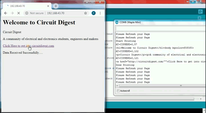
After clicking the link, you see a text on the webpage saying “Data Received Successfully.....”
Complete code with Demonstration Video is given below.
Complete Project Code
//Interfacing ESP8266 Wi-Fi with STM32F103C8
//CIRCUIT DIGEST
//NOTE: Serial is serial monitor with baud rate(9600)
//NOTE: Serial2 (TX2, RX2)is connected with ESP8266(RX,TX)respectively with baud rate (9600)
String webpage="";                                   //String variable to store characters
int i=0,k=0,x=0;                                         //integer variables
String readString;                                   //using readString feature to read characters
boolean No_IP=false;                                 //boolean variables
String IP="";                                         //String variable to store data
char temp1='0';                                      //character variable
String name="<p>Circuit Digest</p><p>A community of electrical and electronics students, engineers and makers</p>";   //String with html notations
String data="<p>Data Received Successfully.....</p>";     //String with html
void check4IP(int t1)                                     //A function to check ip of ESP8266
{
  int t2=millis();
  while(t2+t1>millis())
  {
    while(Serial2.available()>0)
    {
      if(Serial2.find("WIFI GOT IP"))
      {
        No_IP=true;
      }
    }
  }
}
void get_ip()                                           //After cheacking ip ,this is a function to get IP address
{
  IP="";
  char ch=0;
  while(1)
  {
    Serial2.println("AT+CIFSR");                   //GET IP AT COMMAND
    while(Serial2.available()>0)
    {
      if(Serial2.find("STAIP,"))                   //This finds the STAIP that is the STATIC IP ADDRESS of ESP8266
      {
        delay(1000);
        Serial.print("IP Address:");
        while(Serial2.available()>0)
        {
          ch=Serial2.read();                      //Serial2 reads from ESP8266
          if(ch=='+')
          break;
          IP+=ch;
        }
      }
      if(ch=='+')
      break;
    }
    if(ch=='+')
    break;
    delay(1000);
  }
  Serial.print(IP);                                //prints IP address in Serial monitor
  Serial.print("Port:");
  Serial.println(80);
}
void connect_wifi(String cmd, int t)                  //This function is for connecting ESP8266 with wifi network by using AT commands
{
  int temp=0,i=0;
  while(1)
  {
    Serial.println(cmd);                  //Sends to serial monitor
    Serial2.println(cmd);                 //sends to ESP8266 via serial communication
    while(Serial2.available())
    {
      if(Serial2.find("OK"))
      i=8;
    }
    delay(t);
    if(i>5)
    break;
    i++;
  }
  if(i==8)
  Serial.println("OK");
  else
  Serial.println("Error");
}
void wifi_init()                                //This function contains AT commands that passes to connect_wifi()
{
      connect_wifi("AT",100);                   //Sends AT command with time(Command for Achknowledgement)
      connect_wifi("AT+CWMODE=3",100);          //Sends AT command with time (For setting mode of Wifi)
      connect_wifi("AT+CWQAP",100);            //Sends AT command with time (for Quit AP)
      connect_wifi("AT+RST",5000);             //Sends AT command with time (For RESETTING WIFI)
      check4IP(5000);
      if(!No_IP)
      {
        Serial.println("Connecting Wifi....");
        connect_wifi("AT+CWJAP=\"Pramo\",\"pokemon08\"",7000);         //provide your WiFi username and password here
      }
      else
        {
        }
      Serial.println("Wifi Connected");
      get_ip();
      connect_wifi("AT+CIPMUX=1",100);                          //Sends AT command with time (For creating multiple connections)
      connect_wifi("AT+CIPSERVER=1,80",100);                    //Sends AT command with time (For setting up server with port 80)
}
void sendwebdata(String webPage)                          //This function is used to send webpage datas to the localserver
{
    int ii=0;
     while(1)
     {
      unsigned int l=webPage.length();
      Serial.print("AT+CIPSEND=0,");
      Serial2.print("AT+CIPSEND=0,");
      Serial.println(l+2);
      Serial2.println(l+2);
      delay(100);
      Serial.println(webPage);                        //sends webpage data to serial monitor
      Serial2.println(webPage);                       //sends webpage data to serial2 ESP8266
      while(Serial2.available())
      {
        if(Serial2.find("OK"))
        {
          ii=11;
          break;
        }
      }
      if(ii==11)
      break;
      delay(100);
     }
}
void setup()
{
   Serial.begin(9600);                //begins serial monitor with baud rate 9600
   Serial2.begin(9600);               //begins serial communication with esp8266 with baud rate 9600 (Change according to your esp8266 module)
   wifi_init();
   Serial.println("System Ready..");
}
void loop()
{
  k=0;
  Serial.println("Please Refresh your Page");
  while(k<1000)
  {
    k++;
   while(Serial2.available())
   {
    if(Serial2.find("0,CONNECT"))
    {
      Serial.println("Start Printing");
      Send();
      Serial.println("Done Printing");
      delay(1000);
    }
  }
  delay(1);
 }
}
void Send()                                        //This function contains data to be sent to local server
{
      webpage = "<h1>Welcome to Circuit Digest</h1><body bgcolor=f0f0f0>";
      sendwebdata(webpage);
      webpage=name;
      sendwebdata(webpage);
      delay(1000);
      webpage = "<a href=\"http://circuitdigest.com/\"";
      webpage+="\">Click Here to get into circuitdigest.com</a>";
      webpage+=data;
      sendwebdata(webpage);
      Serial2.println("AT+CIPCLOSE=0");                  //Closes the server connection
}
Comments
The ESP8266 isn't powering…
The ESP8266 isn't powering on through Blue Pill. Do I have to connect it through a separate USB breakout board? In that case could I directly give it 3.3V?

it works for me with Serial1 instead of Serial2