

This is the third tutorial in continuation of our previous ESP tutorials, in which we will learn to Program the ESP8266 with Arduino IDE (without Arduino) and Flashing the ESP8266. In previous tutorials we have covered Introduction to ESP8266 WiFi Transceiver and using AT commands with ESP8266. We have also made a development board, using a FTDI Serial Adapter Module, which can be easily used to program the ESP module using both using AT commands and Arduino IDE.
Before we get started, let me tell you why we need to learn the above things. The ESP8266 module comes with a Firmware pre-loaded into it. This Firmware can be used to communicate to the ESP8266 module via AT commands. But, if we use the Arduino IDE this firmware will be over written. This means that once you have used Arduino IDE to program your ESP module you won’t be able to use the AT commands again. Hence, we have to flash the module with the default firmware so that we can start using the AT commands. In this tutorial we will also cover Flashing of ESP8266. Complete detailed is also explained in the Video given at the end.
Prerequisites:
You would need the following components for this project
- ESP8266 Module
- FTDI Breakout Board (3.3V)
- Arduino IDE
- Must have read the Previous tutorial and have made the below connection
Then the most important step is wiring your ESP module properly. This is very well explained in the previous tutorial. The circuit diagram again is shown here for reference

(Check our various ESP8266 based interesting IoT Projects here)
Programming the ESP8266 using Arduino IDE:
Working with ESP modules have become a lot easier since the Arduino Community has started to support it by providing its own library and board manager. This way you don’t have to use the hard way of learning the instruction documentation of the ESP module and program it using AT commands.
In this tutorial let us Set up the Arduino IDE for ESP module and program it to blink a LED light.
Step 1: If you do not have an Arduino IDE download it and install it from here. (make sure the Arduino Version is 1.6.5 or above)
Step 2: Navigate to File -> Preferences to open the below dialog box. In the “Additional Board managers URL” paste the below link as shown in the image. Then press OK
http://arduino.esp8266.com/stable/package_esp8266com_index.json
Step 3: Now, navigate to Tool -> Boards -> Board Managers. Search for ESP8266 by esp8266 community and click on install as shown in the below image
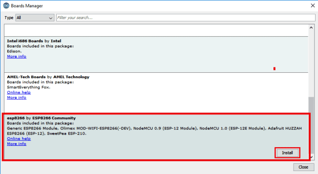
You installation will take some time, once completed we can begin our next step.
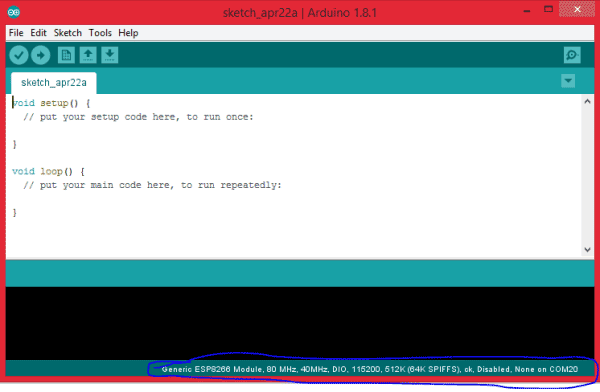
Step 4: Now, Navigate to Tools -> Boards -> Generic ESP8266 modules. You should see the below screen
Step 5: Now let us try uploading the Example blink Program. This program can be found in File -> Examples -> ESP8266 -> Blink.
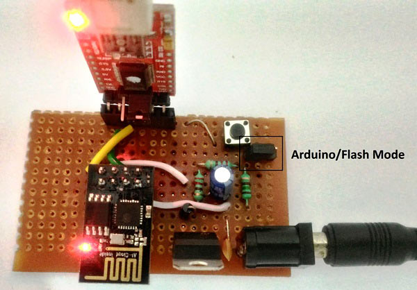
Step 6: Connect your ESP8266 Module and the FTDI board as shown above circuit and make sure your GPIO0 is pulled to ground. To pull down the GPIO0, set the jumper switch as shown in below figure, we have used jumper switch to select between programming through AT command and through Arduino IDE. Then power up the modules and reset it by pressing the pushbutton on the board. If you have followed the previous tutorial on developing the Board, your board should have looked something like this.
Step 7: Now press the upload button, this upload will take a bit more time than the usual Arduino Uploading. So wait for the upload to complete. Once, done you will see the following screen.
You should also see a Blue colour LED blinking on your ESP module. This confirms that the program has been uploaded successfully. The complete procedure is also explained in the video given in end.
After, this if you try to use the AT commands of the module it will not work. To work with AT commands again you have to flash your ESP8266 module with the firmware, which has been explained below.
Also check our simple ESP8266 Tutorials with Arduino:
- Sending Email using Arduino and ESP8266 WiFi Module
- How to Send Data from Arduino to Webpage using WiFi
Flashing ESP8266 Module:
Most of the time while learning to use the ESP8266 Module we will get stuck somewhere and might want to flash the ESP8266 module so that we can get it back to working again. Let us see how we can do it.
Use the same Board above and follow the below steps to Flash the Memory of ESP8266:
Step 1: Download the Flash Download Tools from here. Then download the required firmware, for this tutorial I have downloaded the firmware from here.
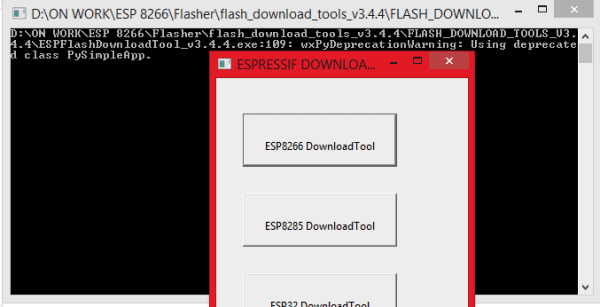
Step 2: Open the Flash Download Tools that we just downloaded. It should look like this below. Click on ESP8266 Download Tool
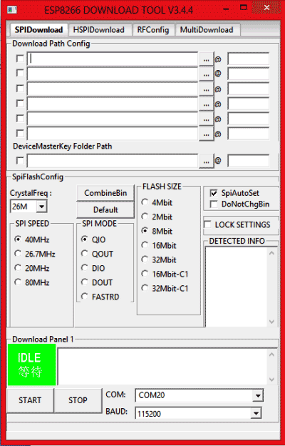
Step 3: A dialog box will open. In which we have to set the Crystal Freq. As 26M, SPI Speed 40MHz, SPI mode QIO, Flash Size 8-bit, COM port as 20 (mine is 20 yours might differ) and baud rate as 115200 as shown below.
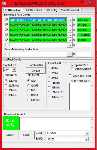
Step 4: Now we have to configure the download path. There will be five bin files inside the firmware folder that we downloaded in step 1. The name of the bin file, their location and address is given in the table below
|
Name of the Bin file |
Location |
Address |
|
esp_init_data_default.bin |
ESP8266_NONOS_SDK_V1.4.0_15_09_18\esp_iot_sdk_v1.4.0\bin |
0xFC000 |
|
blank.bin |
ESP8266_NONOS_SDK_V1.4.0_15_09_18\esp_iot_sdk_v1.4.0\bin |
0xFE000 |
|
boot_v1.4(b1).bin or later |
ESP8266_NONOS_SDK_V1.4.0_15_09_18\esp_iot_sdk_v1.4.0\bin |
0x00000 |
|
user1.1024.new.2.bin |
ESP8266_NONOS_SDK_V1.4.0_15_09_18\esp_iot_sdk_v1.4.0\bin\at\512+512 |
0x01000 |
|
user2.1024.new.2.bin |
ESP8266_NONOS_SDK_V1.4.0_15_09_18\esp_iot_sdk_v1.4.0\bin\at\512+512 |
0x81000 |
Once the files are configured, it should look something like this below.
Step 5: Now, power on your hardware, connect your GPIO0 pin to ground and reset the module by momentarily connect the RST pin to ground and leave it free. Use jumper switch to ground the GPIO0 pin and reset the module using Push button. Then your hardware will look something like this below.
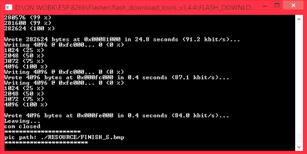
Step 6: Now click on the START button and your ESP module should start getting flashed. You screen will look something like this
Once the flash is done you will get the below screen, this indicates that your Module is flashed successfully
Now, you can close all the windows and power off your module. Then follow the steps in “PROGRAMMING USING AT COMMANDS” and you should be able to work with AT commands again.
The complete procedure is also shown in the video below.
We have covered all the basics required to do your own projects with ESP8266 Module. From our next tutorials we will start building cool stuff using the ESP8266 Module.
Don’t forget to check our other ESP8266 based Projects.
