

A Switch Mode Power Supply (SMPS) is an indispensable part of any electronic design. It is used to convert mains high-voltage AC to low voltage DC, and it does it by first converting the mains AC to high voltage DC, then switching the high voltage DC to generate the desired voltage. We have already made a few SMPS circuits earlier, like this 5V 2A SMPS circuit and 12V 1A TNY268 SMPS circuit. We even did build our own SMPS transformer that could be used in our SMPS designs along with the driver IC.
You may not notice it but most of the household products like mobile charger, laptop charger, Wi-Fi Routers, require a switching mode power supply to operate, and most of those are 5V one. So with that in mind, in this article, we will show you how you can build a 5V, 1A SMPS circuit by salvaging parts from an old throwaway PC ATX power supply.
Warning: Working with AC mains needs prior skills and supervision. Do not open an old SMPS or try building a new one without experience. Be careful around charged capacitors and live wires. You have been warned, proceed with caution, and take expert guidance wherever needed.
Design Considerations for 5V 1A Power Supply
Before we continue further, let's clear out some of the basic design consideration and protection features.
Why should you build an SMPS circuit from a computer power supply?
For me it's cheap, then again cheap is a very expensive word, it's literally free. You may ask how so? Just talk to your local PC service shops, they will give it to you for free at least that was the case for me. Also, ask your friends if they have any of those broken ones lying around.
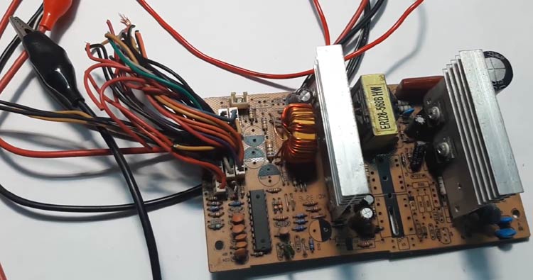
Building/procuring the transformer for the circuit is the most crucial part of any SMPS design, but this method completely avoids this step by salvaging the transformer, also it comes with a very good learning experience if you are an electronic junky like me. My ATX power supply after salvaging the required parts are shown below.
With this design, you can add a potentiometer and vary the output voltage a little. that may come in handy in some cases and the most interesting thing about the circuit is that it's made with very generic parts so if something blows up finding and replacing them is a very easy task.
SMPS circuits function differently in different conditions, if you are building this circuit knowing the actual input-output characteristic can help you to debug the circuit if you find any problem with it.
Input Voltage:
Since the input voltage of the standard PC PSU is 220V, our salvaged circuit also operates on that voltage. But with my current table setup, I will try to operate the circuit with an 85V input voltage as well.
Output voltage:
The output voltage of the circuit is 5V with 1A of current rating, which means this circuit can handle a power of 5W. This circuit operates under constant voltage mode, so the output voltage should stay pretty much the same irrespective of load current.
Output Ripple:
The transformer in this circuit is made by a professional manufacturer so we can expect a low ripple. Since its construction in a dotted board, we can expect a little more ripple than usual.
Protection Features:
In general, there are many protection circuits SMPS designs but our circuit is made from an old PC PSU, so we can add or subtract protection features as per the requirement of our final application. You can also check out the following protection circuits we build earlier.
- Over Voltage Protection Circuit
- Reverse Polarity Protection Circuit
- Short Circuit Protection Circuit
- Inrush Current Protection
- Hot Swap Controller Protection Circuit
I am going to use this circuit to power my IoT projects. So I decided to go with a minimum protection feature which is a fusible resistor at the input, and an overvoltage protection circuit at the output section.
So, to summarize, the AC mains voltage for our power supply would be 220V AC, the output voltage will be 5V DC with 1A of maximum output current. We will try to make the output ripple voltage as low as we can and we have an input fusible resistor with an output overvoltage protection circuit.
Components Required for 5V 1A SMPS Circuit
|
Sl.No |
Parts |
Type |
Quantity |
Part In Schematic |
|
1 |
4.7R |
Resistor |
1 |
R1 |
|
2 |
39R |
Resistor |
1 |
R10 |
|
3 |
56R,1W |
Resistor |
1 |
R9 |
|
4 |
100R |
Resistor |
2 |
R7, R6 |
|
5 |
220R |
Resistor |
1 |
R5 |
|
6 |
100K |
Resistor |
1 |
R2 |
|
7 |
560K, 1W |
Resistor |
2 |
R3, R4 |
|
8 |
1N4007 |
Diode |
4 |
D2,D3,D4,D5 |
|
9 |
UF4007 |
Diode |
1 |
D6 |
|
10 |
1N5819 |
Diode |
1 |
D1 |
|
11 |
1N4148 |
Diode |
1 |
D7 |
|
12 |
103,50V |
Capacitor |
C4 |
|
|
13 |
102, 1KV |
Capacitor |
2 |
C3 |
|
14 |
10uF,400V |
Capacitor |
1 |
C1 |
|
15 |
100uF,16V |
Capacitor |
1 |
C6 |
|
16 |
470uF |
Capacitor |
2 |
C7, C8 |
|
17 |
222pF,50V |
Capacitor |
1 |
C5 |
|
18 |
3.3uH, 2.66A |
Inductor |
1 |
L2 |
|
19 |
2SC945 |
Transistor |
1 |
T1 |
|
20 |
C5353 |
Transistor |
1 |
Q1 |
|
21 |
PC817 |
Optocoupler |
1 |
OK1 |
|
22 |
TL431CLP |
Voltage Reference |
1 |
VR1 |
|
23 |
10K |
Trim Pot |
1 |
R11 |
|
24 |
Screw Terminal |
5mm |
2 |
S1, S2 |
|
25 |
1N5908 |
Diode |
1 |
D9 |
|
26 |
Transformer |
From PC PSU |
1 |
TR1 |
5V 1A SMPS Circuit Diagram
The below image shows the schematics of 5V 1A SMPS Power supply that we will build in this tutorial.

I built the circuit on a breadboard and it looked like this when completed.
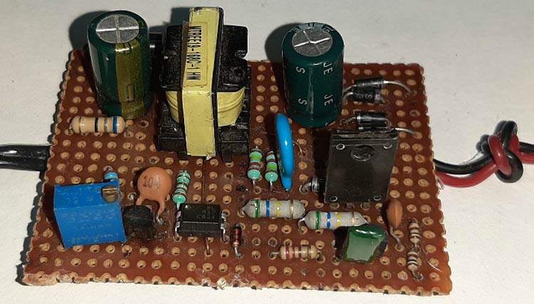
Let's understand the circuit by breaking it down to many functional blocks and let's understand each block.
The Fusible Resistor:
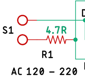
First, we have R1 which serves two purposes. First, it acts as a fusible resistor. Second, it acts as a current limiting resistor.
The Bridge Rectifier & the Filter:
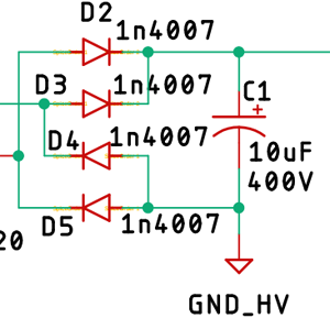
Next, we have 1N4007 diodes, D2, D3, D4, D5, four of which form the bridge rectifier, along with a 10uF filter capacitor to convert AC to DC.
Please note that I have removed the PI filter because I am not going to be using this power supply other than charging a battery, if you intend to use this other way, an EMI filter is must, you can always pull it out from the same power supply. If you are not sure what is PI filter or how it works, you can check out the linked article. You can also check out other designs to reduce EMI in SMPS circuit that we have discussed earlier.
The Start-up Resistors:
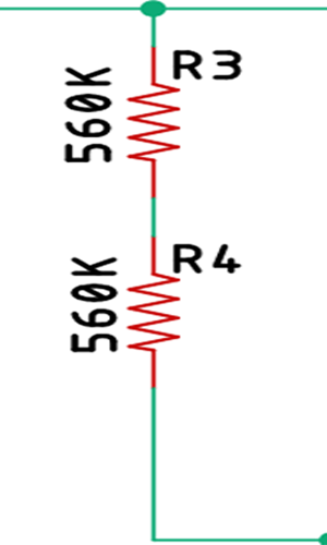
R3 and R4 form the startup resistors, when the power is applied, the startup resistors are responsible for powering the base of the primary switching transistor, I will discuss more about the resistor later in the article.
Collector Voltage Limiting Clamp:
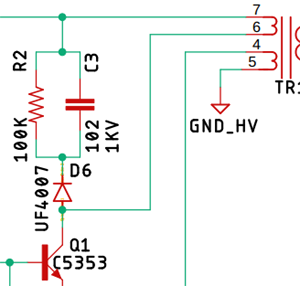
To limit the collector voltage of the primary switching transistor Q1 C3, R2, and D6 form a clamp circuit, and this is a very good example of using a snubber network to decrease the peak voltage at turn-off and to damp the ringing. In most cases, a very simple design technique can be used to determine suitable values for the snubber components (Rs and Cs). In those cases where a more optimum design is needed, a somewhat more complex procedure is used.
Primary & the Auxiliary Switching Transistor:
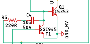
Transistor Q1, C5353 is the main switching transistor and T1 is the auxiliary switching transistor in the circuit. C4 and R5 form the primary oscillator which generates the main switching signal.
Feedback and Control Circuit:
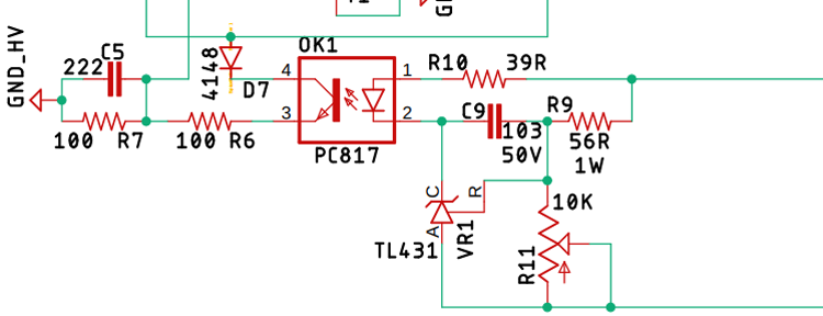
The PC817 optocoupler OK1 along with the voltage reference VR1 and the diode 4148 forms the Feedback & Control Circuit other resistor presents in this portion only acts as a voltage divider, current limiting resistor, and filter capacitor. Other than that, I have added the potentiometer R11 to trim the voltage as per requirement.
Transformer, Output Rectifier, and Filter:
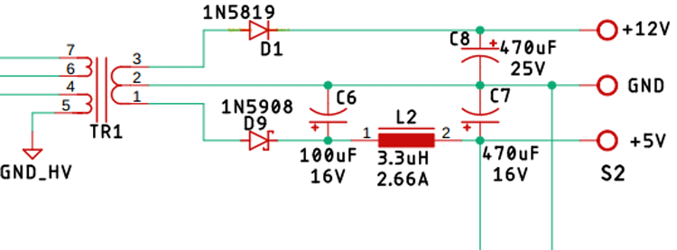
The transformer T1 is made from a ferromagnetic material, which not only converts the high voltage AC to a low voltage AC but also provides galvanic isolation. There are 4 windings in the transformer T1 Pin 1, 2, and 3 is the secondary winding, Pin no 4, 5 is the auxiliary winding, pin no 6 and 7 is the primary winding.
Diode D1 and D9 are the rectifier diodes for the circuit. Capacitor C8 is responsible for filtering the 12V, and the capacitor C6 & C7 along with L2 forms the PI filter for the output section.
Over Voltage Protection Circuit:
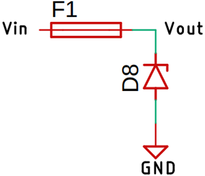
An additional overvoltage protection circuit can be added to protect your application device for getting damaged, it's a very simple circuit consist of a fuse and the Zener diode as you can see it above If an overvoltage condition occurs, the Zener diode will blow up, thus blowing up the Fast Blow Fuse with it.
5V-1A SMPS Circuit Working
Now, that's cleared out, let's understand how the circuit works, When the power is applied to the circuit, the mains AC gets rectified and filtered by the rectifying diodes and capacitor. After that, the two startup resistors R3, R4 limits the current to the base of the transistor, that's why the primary transistor gets on slightly, now a little current flows through the primary winding of the transformer which is pin 6 and 7 of the transistor.
This small amount of current energizes the auxiliary winding, this auxiliary winding starts charging the 103pF capacitor C4 through the 220 Ohms resistor R5. Again the voltage at the auxiliary side is connected to the collector of the optocoupler with a 1N4148 rectifying diode, this voltage gets out of the emitter of the optocoupler and gets divided with a voltage divider. Now the C5 the 222PF capacitor starts charging When this capacitor is charged to a certain level, the auxiliary transistor T1 gets on and the primary transistor gets turned off, and the capacitor C5 gets discharged
And the cycle starts repeating once again, thus a switching signal is generated. Once the switching process starts, the voltage gets induced at the secondary of the transformer from the secondary a feedback circuit is made with the help of VR1 the Tl431 voltage reference, by adjusting the reference voltage, we can set the turn on and turn off time of the auxiliary transistor, thus we can control the output voltage.
Building the SMPS Circuit
For this demonstration, the circuit is constructed in a dotted board with the help of the schematic; please note that I am testing the circuit on my bench for demonstration so I did not include many protections features like over-voltage protection and short circuit protection. If you are using this to power something else, it's recommended to those protection and filter circuits on.
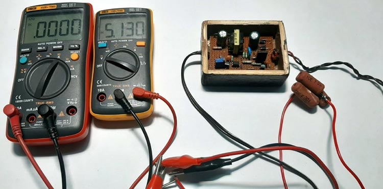
The above test setup was used to test the circuit, the output voltage of the power supply was adjusted to 5.1V using the potentiometer and it's a 1A power supply so it can pull 1A current at peak condition.
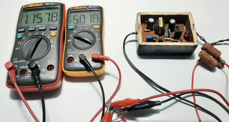
As you can see in the above image, for testing with the load, I used some resistors as a load that consumed about 1.157A from our SMPS circuit at 5V. The complete testing video can be found at the bottom of this article.

5V-1A SMPS Circuit Design Improvements
There are quite a few things that can be improved in this circuit like an EMI filter can be added at the input to improve the EMI response of this circuit. Then an Output overcurrent and short circuit protection can be added to improve the overall performance of the circuit. Also, an Input overvoltage and surge protection can be added to protect it from input surge. And finally, if the circuit is constructed in a PCB board, the EMI response can be improved drastically.
Hope you understood the tutorial and learned how to build your SMPS circuits. If you have any questions, leave them in the comment section below or use our forums for more questions.

How do obtain 5V, 12V & 16V from the above circuit ?