Protection circuits, like reverse polarity protection, short-circuit protection, and over/under voltage protection, are used to protect any electronic appliance or circuit from any sudden mishap. Generally fuse or MCB is used for overvoltage protection. Here in this circuit, we will build a simple overvoltage protection circuit without using a fuse.
Overvoltage protection is a power supply feature that cuts off the supply whenever the input voltage exceeds the preset value. For protection from high voltage surges, we always use overvoltage protection or a crowbar protection circuit. A crowbar protection circuit is a type of overvoltage protection that is most commonly used in electronic circuits.
Table of Contents
There are many different ways to protect your circuit from overvoltage. The simplest way is to connect the fuse to the input supply side. But the problem is that it’s a one-time protection, because as the voltage exceeds the preset value, the wire inside the fuse will burn and break the circuit. Then you have to replace the damaged fuse with a new one to make the connections again.
Here in this circuit, a Zener Diode and a Bipolar Transistor are used for automatic overvoltage protection. It can be done by two methods,
1. Zener Voltage Regulator Circuit: This method regulates the input voltage and protects the circuit from overvoltage by supplying a regulated voltage, but it doesn't disconnect the output part when the voltage exceeds the safety limits. We will always receive an output voltage less than or equal to the rating of the Zener diode.
2. Overvoltage Protection Circuit using Zener Diode: In the second method of overvoltage protection, whenever the input voltage exceeds the preset level, it disconnects the output part or load from the circuit.
Overvoltage Protection Devices
Before diving into our Zener-based circuit, let's quickly look at what else is out there. You've got fuses and MCBs, which are reliable, but fuses are one-shot deals. MOVs are fast as well as cheap, but they wear out over time. TVS diodes are lightning fast and precise, but cost more. Gas discharge tubes handle massive currents but are slower to react. Then there are commercial surge protectors that do everything but are way overkill for hobby stuff.
So why build your own? You get exact voltage thresholds, automatic reset when things calm down, and it costs pennies for small projects. Plus, you actually know how your protection works instead of trusting some black box.
Zener-Based Overvoltage Protection Circuit
A Zener Voltage Regulator protects the circuit from overvoltage and also regulates the input supply voltage. Circuit diagram for Overvoltage Protection using Zener Voltage Regulator is given below:

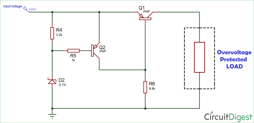
The preset voltage value of the circuit is the critical value over which either the supply is disconnected or it won’t allow any voltage above that value. Here, the Preset voltage value is the rating of the Zener. Like, we are using a 5.1V Zener diode, then the voltage at the output will not exceed 5.1V.
When the output voltage increases, the base-emitter voltage decreases; due to this, transistor Q1 conducts less. As Q1 conducts less, it reduces the output voltage, hence maintains the output voltage constant.
The output voltage is defined as:
VO = VZ - VBE
Where:
VO = Output voltage
VZ = Zener breakdown voltage
VBE = Base-emitter voltage

The overvoltage protection circuit diagram below the components section is built using a Zener diode and a PNP transistor. This circuit disconnects the output when the voltage exceeds the preset level. The preset value is the rated value of the Zener diode connected to the circuit. You can even change the Zener diode according to your suitable voltage value. The disadvantage of the circuit is that you may not find the exact value of the Zener diode, so choose one that has the nearest rating to your preset value.
Materials Required
| Component | Specification | Quantity |
| FMMT718 PNP Transistor | Low saturation voltage | 2nos. |
| Zener Diode | 5.1V (1N4740A) | 1nos. |
| Resistors | 1k, 2.2k, and 6.8k | 1nos. (each) |
| Breadboard | Standard | 1 |
| Connecting Wires | Various lengths | As needed |
Circuit Diagram
Circuit Operation
When the voltage is less than the preset level, the base terminal of Q2 is high and as it is a PNP transistor, it turns OFF. And, when Q2 is off condition, the base terminal of Q1 will be LOW, and it allows the current to flow through it.
Now, when the voltage exceeds the preset value, the Zener diode starts conducting, which connects the base of Q2 to ground and turns ON Q2. When Q2 turns ON, the base terminal of Q1 gets HIGH, and Q1 turns ON, which means Q1 behaves as an Open Switch. Hence, Q1 does not allow the current to flow through it and protects the Load from exceeding voltage.
Now we also need to consider the voltage drop across the transistors; it should be low for proper accuracy of the circuit. So we have used FMMT718 PNP transistor, which exhibits a very low VCE saturation value, due to this, the voltage drop across the transistors is low.
Advantages
- No fuse drama: Forget swapping fuses every time something spikes. This circuit resets itself. Plug it in, chill, it’s got your back.
- Cheap and cheerful: Just a Zener diode, a couple of transistors, and some resistors. Hobbyist heaven.
- Pick your cutoff voltage: Swap the Zener, and boom, you choose when it should kick in. Want 5V, 9V, 12V? Easy.
- Load gets real protection: Unlike a basic voltage regulator that just limits voltage, this actually cuts the current when things go wild. Your toys are safe.
- Quick on the draw: Zeners' reaction is almost instant, so voltage spikes get handled before your gadgets even have a reason to cry for help.
Disadvantages
- Voltage isn’t laser-precise: Zener tolerances mean the cutoff might be a little off. Don’t expect perfection.
- Tiny heat alert: Some energy gets wasted in the Zener and transistors. Not a biggie for small projects, but high-current stuff might get warm.
- Not for monster loads: Mains voltage or big motors? No, stick with fuses, MOVs, or proper surge protectors.
- Hunting for Zeners: Sometimes your exact desired voltage isn’t on the shelf, so you pick the closest match.
- Minor voltage drop: Your load won’t see the exact input voltage, thanks to the transistor drop.
FAQ Around Overvoltage Protection Circuits
Q1: What is overvoltage protection?
It is a feature that keeps your electronics safe when the input voltage goes higher than it should. Basically, it either limits the voltage or disconnects the supply so your devices don’t get fried.
Q2: How does a Zener diode help?
A Zener diode has a fixed voltage at which it starts conducting. When the input voltage goes above this, it either regulates the voltage or triggers a transistor to cut off the load. Your electronics stay safe without you doing anything.
Q3: What is the difference between a Zener voltage regulator and a Zener-based overvoltage protection circuit?
A Zener voltage regulator keeps the output voltage under control but does not disconnect the load if the input spikes. The Zener-based overvoltage protection actually disconnects the load if the voltage goes too high. It is like having a tiny automatic guard in your circuit.
Q4: Can I pick any cutoff voltage?
Yes. You just choose a Zener diode close to the voltage you want. Need 5 volts, 9 volts, or 12 volts? Swap the Zener and you are done. Sometimes the exact voltage is not available, so pick the closest one.
Q5: Are there any drawbacks?
A few. The cutoff is not super precise because of Zener tolerances. High-current loads can make the transistors warm. And this is not meant for mains voltage or big motors. For those, stick to proper surge protectors or fuses.
Related Circuits and Projects
Advance your skills with practical projects that protect and monitor electrical systems. Explore AC mains overvoltage protection, op-amp-based overcurrent detection, and microcontroller-powered high/low voltage detectors to make your electronics safer and smarter.
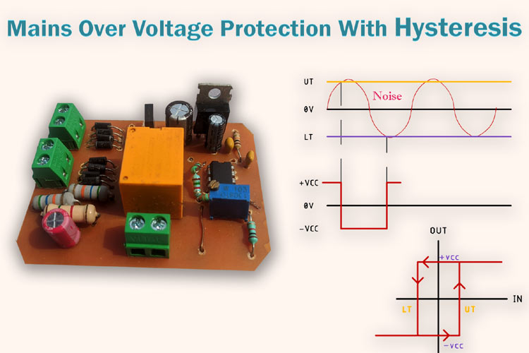
230V AC Mains Over Voltage Protection Circuit
Learn how to design a mains overvoltage protection circuit that prevents appliances from getting damaged due to sudden voltage spikes.
Overcurrent Protection using Operational Amplifier
Build an adjustable overcurrent protection circuit featuring auto-restart functionality, driven efficiently by an op-amp.
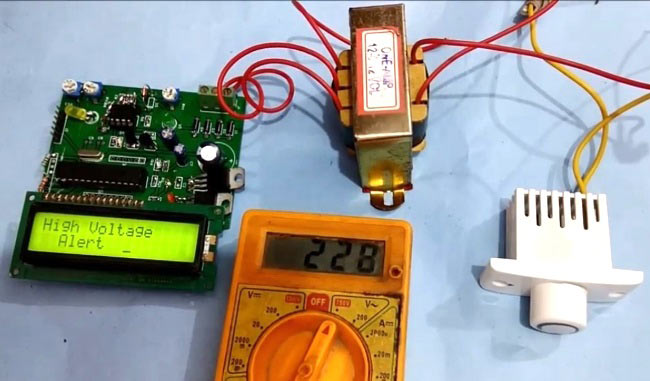
High and Low Voltage Power Detector Circuit with Message Alert using PIC Microcontroller
Create a low-cost voltage detector circuit that automatically cuts off power to appliances during high or low voltage conditions, keeping your devices safe.


