

Display advertising plays a very importing role in marketing and there are several advertisement methods like newspapers, posters, glow signboards, etc. but digital LED display boards are getting popular nowadays because of their reliability and advantages. Although they are a little bit expensive still they are durable and customizable, like the advertising text can be changed easily whenever needed and they can also be used as Digital Notice Board at any public place. We previously used an 8x8 LED matrix with many boards to control the text displayed over it, today we will use the P10 display with Arduino.
In this tutorial we are going to use a 32x16 LED dot Matrix display module which is also known as P10 LED Display Module to display a scrolling text by using Arduino UNO. P10 modules can be cascaded to build any size of the advertising board.
Required Components
- Arduino UNO-1
- 32*16 P10 LED display module-1
- 16 Pin FRC connector-1
- 5V DC,3 AMP SMPS
- Connectors
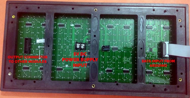
Working of a P10 LED Matrix Module
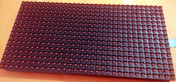
A P10 LED Display Module is the most suitable for designing any size of outdoor or indoor LED display advertisement board. This panel has a total of 512 high brightness LEDs mounted on a plastic housing designed for best display results. Any number of such panels can be combined in any row and column structures to design an attractive LED signboard.
The 32*16 module size means that there are 32 LEDs in each row and 16 LEDs in each column. So there is a total of 512 numbers of LEDs present in each module unit.
Features of a P10 LED Matrix Module:
- Brightness: 3500-4500nits
- Max Power Consumption: 20W
- Voltage Input: DC 5V
- IP65 Waterproof
- 1W Pixel Configuration
- High Viewing Angle
- High Contrast Ratio
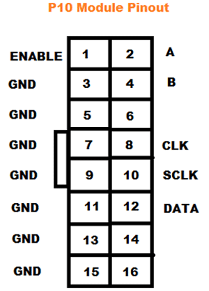
Pin description of P10 display module:
- Enable: This pin is used to control the brightness of the LED panel, by giving a PWM pulse to it.
- A, B: These are called multiplex select pins. They take digital input to select any multiplex rows.
- Shift clock (CLK), Store clock (SCLK) and Data: These are the normal shift register control pins. Here a shift register 74HC595 is used.
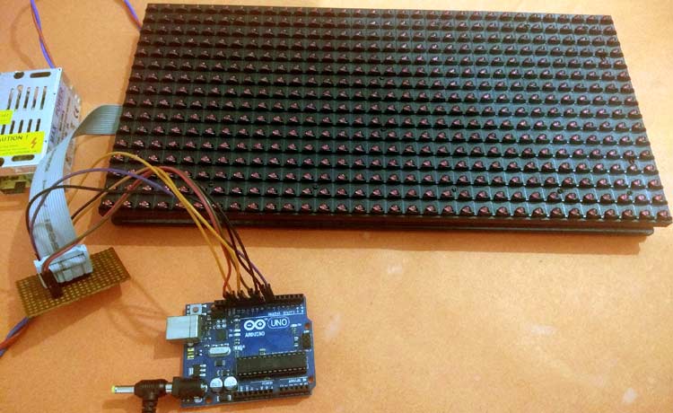
Circuit Diagram
Complete circuit diagram for P10 module with Arduino is given below:

Arduino UNO and P10 display modules are interconnected as per the pin mapping are shown below:
|
P10 LED Module |
Arduino UNO |
|
ENABLE |
9 |
|
A |
6 |
|
B |
7 |
|
CLK |
13 |
|
SCLK |
8 |
|
DATA |
11 |
|
GND |
GND |
Note: Connect the Power terminal of the P10 module to 5V DC SMPS separately. It is recommended to connect a 5V, 3 Amp DC power supply to a single unit of P10 LED module. If you are planning to connect more numbers of the module, then increase your SMPS rating accordingly.
P10 LED Module programming with Arduino
After the successful completion of the hardware setup, now it’s time to program Arduino. Complete code for this 10 Led Display Arduino along with the video is given at the end of this tutorial. The stepwise description of the code is given below.
First of all, include all the dependent libraries in the program. Here we are using “DMD.h” Library for P10 led operations, download this library from here and install it in Arduino IDE. After that include the library for “TimerOne.h” which will be used for interrupt tasks. This library can be downloaded from here.
Then, include all the required fonts library, in our case we are using “Arial Black font” for the display.
#include <SPI.h>
#include <DMD.h>
#include <TimerOne.h>
#include "SystemFont5x7.h"
#include "Arial_black_16.h"
In the next step, define the number of rows and columns for the LED display board. In our case we are using only one module, so ROW value and COLUMN value will be 1. Then define the font name- Arial_Black_16 for the text scrolling on display board.
#define ROW 1
#define COLUMN 1
#define FONT Arial_Black_16
DMD led_module(ROW, COLUMN);
Function scan_module() which checks for any incoming data from Arduino side through the SPI Terminals. If yes, then it will trigger an interrupt pin for doing certain events.
void scan_module()
{
  led_module.scanDisplayBySPI();
}
Inside setup(), initialize the timer and attach the interrupt to the function scan_module. Function clearScreen(true) is used to set all pixels are off initially to clear the display board.
void setup()
{
  Timer1.initialize(2000);
  Timer1.attachInterrupt(scan_module);
  led_module.clearScreen( true );
}
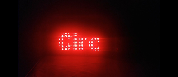
Then, to display a string in the module, select the font using selectFont() function and print a string message “Welcome to Circuit Digest” in the display using drawMarquee() function.
   led_module.selectFont(FONT);
   led_module.drawMarquee("Welcome to Circuit Digest",25, (32 * ROW), 0);
Finally, to scroll the text on the LED display board shift the whole message from Right to Left directions using a certain time period.
long start = millis();
    long timming = start;
    boolean flag = false;
    while (!flag)
    {
      if ((timming + 20) < millis())
      {
        flag = led_module.stepMarquee(-1, 0);
        timming = millis();
      }
    }
So this is how you can make a Scrolling Text Signboard using Arduino and LED matrix.
Complete code and demonstration video is given below.
Complete Project Code
#include <SPI.h>
#include <DMD.h>
#include <TimerOne.h>
#include "SystemFont5x7.h"
#include "Arial_black_16.h"
#define ROW 1
#define COLUMN 1
#define FONT Arial_Black_16
DMD led_module(ROW, COLUMN);
void scan_module()
{
  led_module.scanDisplayBySPI();
}
void setup()
{
  Timer1.initialize(2000);
  Timer1.attachInterrupt(scan_module);
  led_module.clearScreen( true );
}
void loop()
{
    led_module.selectFont(FONT);
    led_module.drawMarquee("Welcome to Circuit Digest",25, (32 * ROW), 0);
    long start = millis();
    long timming = start;
    boolean flag = false;
    while (!flag)
    {
      if ((timming + 20) < millis())
      {
        flag = led_module.stepMarquee(-1, 0);
        timming = millis();
      }
    }
  }
Comments
Hello, Can I replace the…
Hello,
Can I replace the Arduino UNO board with an Arduino Mega board using the same wiring?
Hello! Firslty I want to say…
Hello! Firslty I want to say thanks a lot for this guide. But I want to use six P10 matrices, 3 x 2 position. Is it possible? (without any new circuit)
Is it possible to replace …
Is it possible to replace 'Hello' with 'Modern Church'?" ( Myanmar Sar "ထိန်သစ်ကျောင်း"

Can I make an order of p10smd 16x32 led with Arduino & power supply?